Wissam Tedros
-
IMU Tap detection
11/09/2023 at 22:29 • 0 commentsno buttons, no switches, no touch screens! the LSM6ds032X has a neat little feature that detects taps, double taps along the 3 axis x y and z, so here's a quick test that enables the robot to only wake up when I tap on its top cover :)
this wake up routine was only possible thanks to the analog position feedback that i implemented using the existing potentiometers available from the servo's feedback loop, as to start up, the dog must know its position at power up, which is only possible when you have a position sensor on each joint, and instead of adding 12 more sensors to do that, I simply added an additional wire that hooks to the middle pin of the potentiometer inside! -
Results
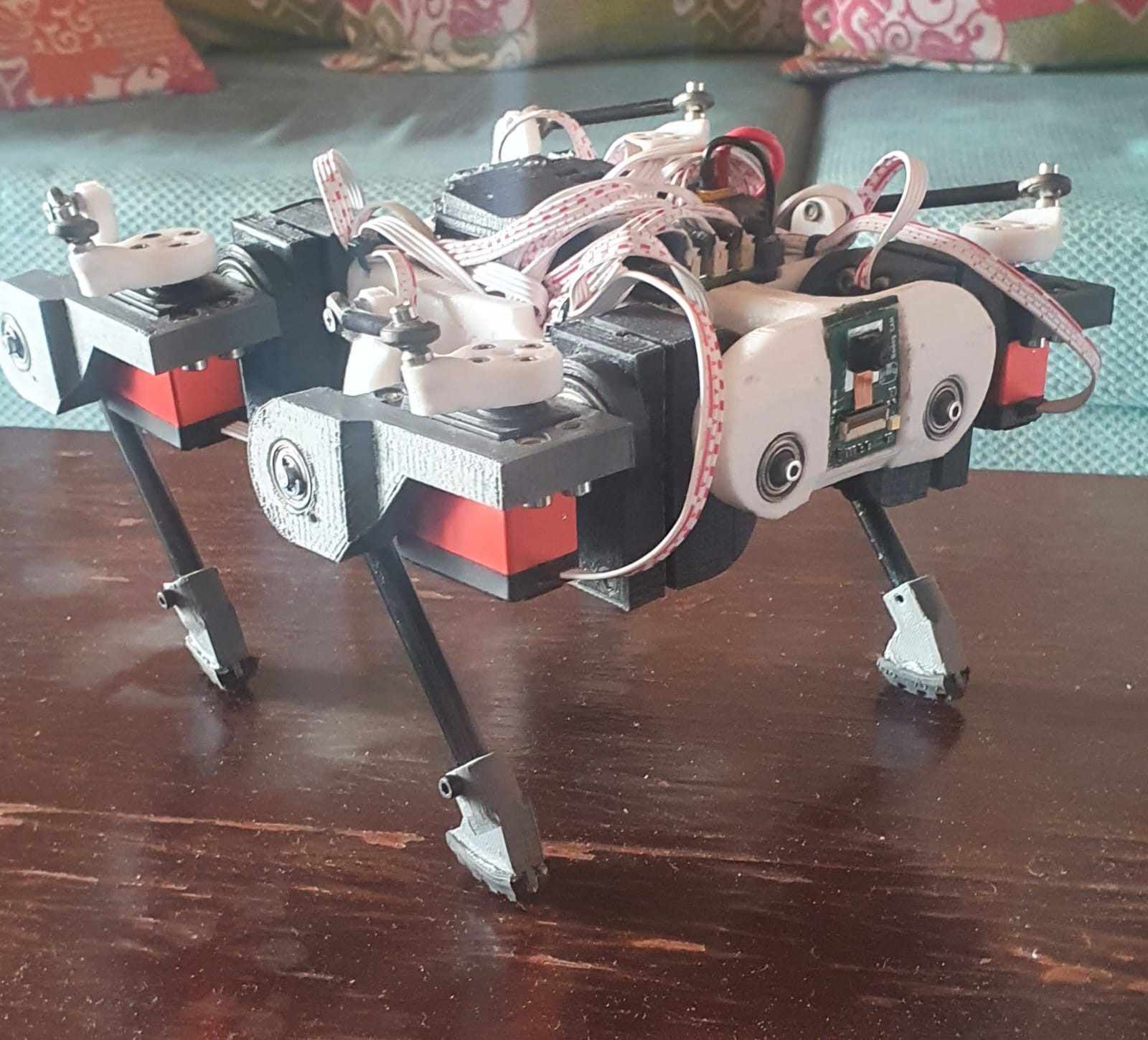
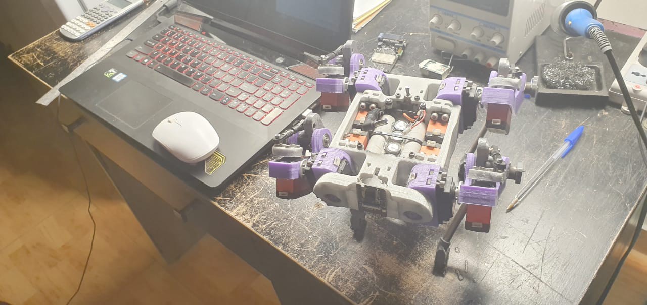
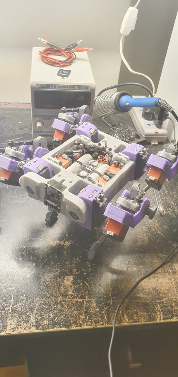
11/09/2023 at 22:25 • 0 commentsLast year's results were greatly satisfying, so after being confident enough with my design I decided to upgrade my servos to Brushless DC motors, for the same voltage and torque rating, but much faster response and higher efficiency.
in the videos below you can see the response of the bot to balancing and trotting, all being merely but position control of the servos, Torque control is yet to be implemented, it will be my next challenge. -
Load switch circuit
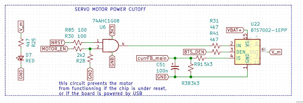
10/09/2022 at 11:00 • 0 commentslet's talk about this circuit, as I think it is one of the most important features on my board.
![]()
Anyone who made a robot and chose standard RC servos as actuators, might already understand why this circuit it present, especially with 12 quite powerful servos.
Ever pressed the reset button on your microcontroller and all the servos started acting crazy and brutally moving left and right? the answer is probably yes, and that is due to the servo signal pin picking up some random signals while the microcontroller is in reset mode and all the GPIOs are floating.
This circuit Prevents that, how? simple, an IC called load switch, that acts like a mechanical switch but except it closed or open based on the input state of its Vin pin, only when Vin is HIGH, the switch is closed, and V_m = VBAT+
now when is Vin HIGH? when the NRST and MOTOR_EN(GPIO OUTPUT pin) are both high, NRST is the reset state of the microcontroller, for the STM32f4, when NRST is HIGH, then the chip is in "run" mode, when pulled LOW, the chip is in reset mode.
So, only when the microcontroller is running, AND the GPIO output is set HIGH, then the servos receive power, when the chip is in reset mode, say you want to flash by SWD, or just press the reset button, all power to the servos is cut, and no matter what the signal pin of the servos pick up during reset, they won't move to unpredictable positions.
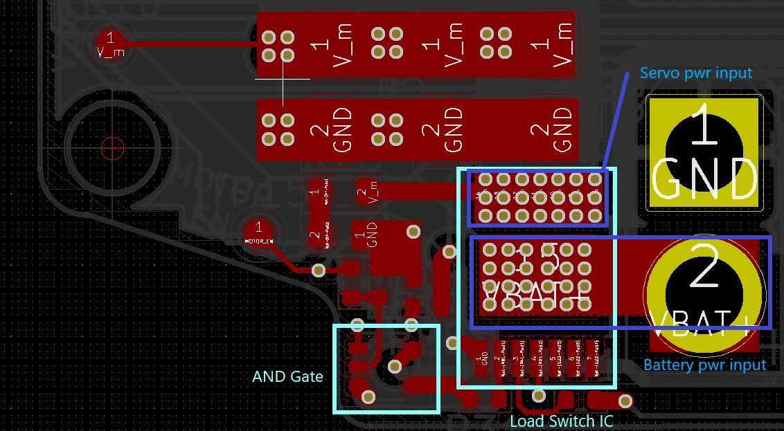
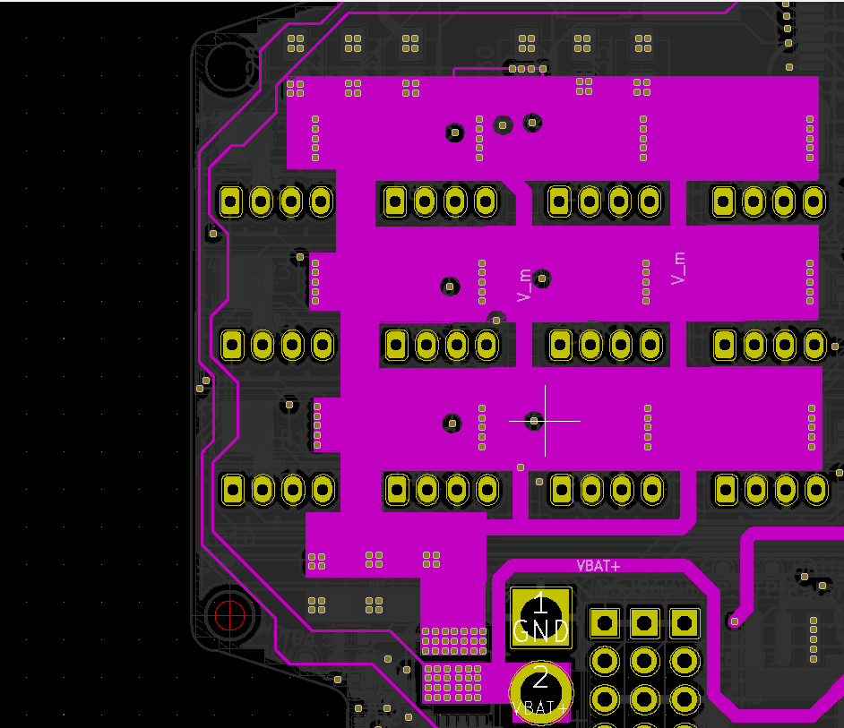
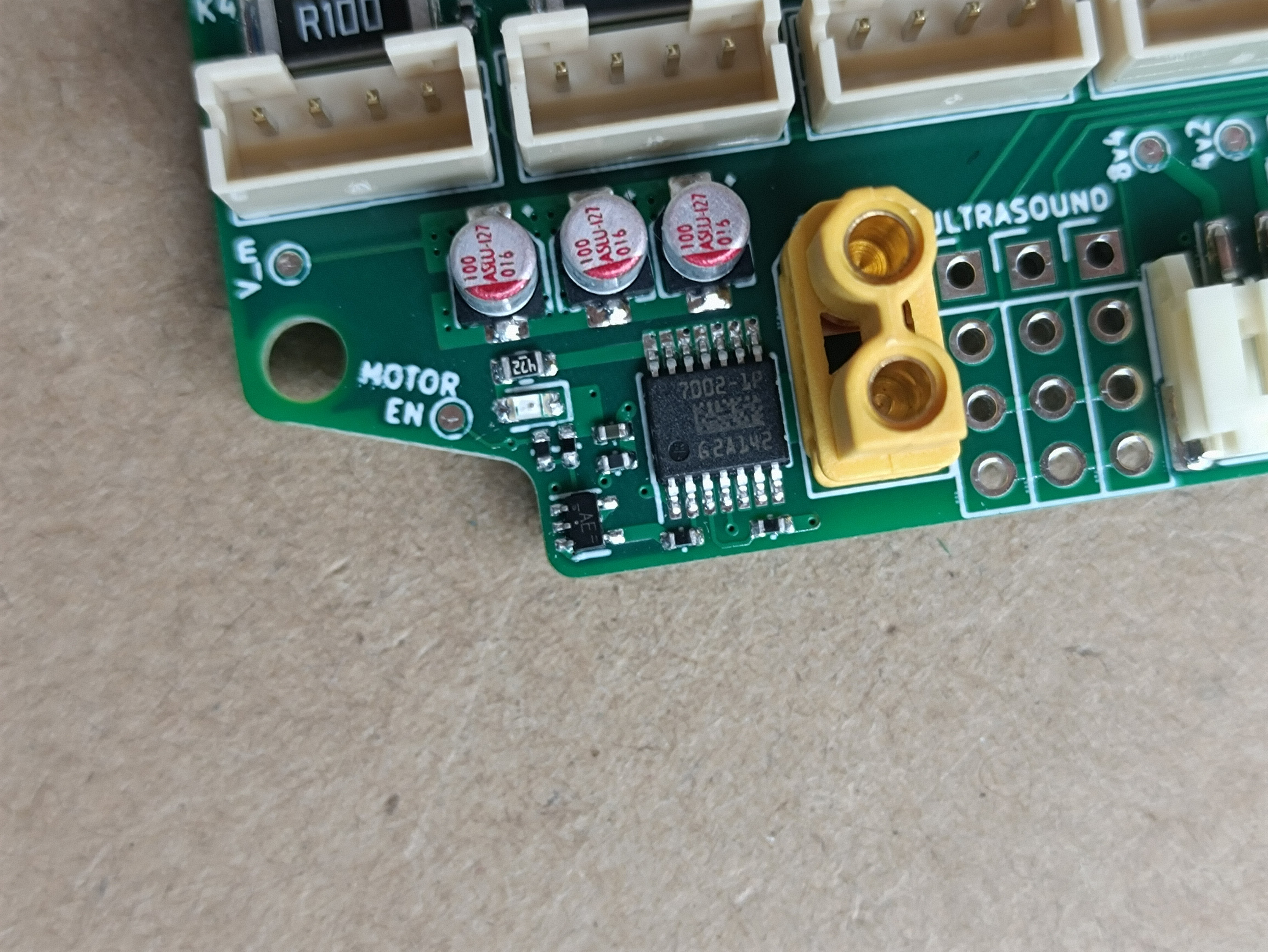
Here is a closer look at the PCB layout of that circuit, since its location is on the edge of the board, I decided to use all 4 copper layers from the battery connector to the load switch, this particular switch is good for a lot more current than the robot ever draws, after hours of usage it barely gets warm, the circuit works like a charm, of course there's is an indicator LED to confirm that the output voltage is present.
the above schematic also points out that the switch will not be closed if the board is powered under USB, this is done by software (I should have pointed this out), this is just for safety reasons, when the batteries are charging or when flashing by DFU.
![]()
![]()
-
First Steps
10/09/2022 at 10:33 • 0 comments![]()
After plenty of hard work and preparations, the first Presentation of RoDog happened in September of 2022, showcasing all movements, some control and the capabilities of the Motherboard, this is the first step towards making quadruped robots as small as this one, capable of navigating indoors and outdoors autonomously with sophisticated software and hardware, while being accessible and affordable.
Here you will find a link to the presentation highlights:
Cheers for more to come! This is only the beginning
-
PCB Manufacturing
08/26/2022 at 16:51 • 0 commentsIn this blog I will walk you through how you can order one of the Boards for yourself, and present you my experience with PCBWay, who decided to Sponsor my board, Big shoutout for them :)
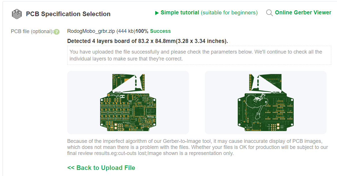
PCBWay has a quick PCB order option where you can simply Upload the GRB.zip files, then the page will automatically load again with all the parameters needed to proceed with the order. Do not worry if the small GRBR viewer shows with some defects, you can have a proper view by visiting their online Gerber viewer.
![]()
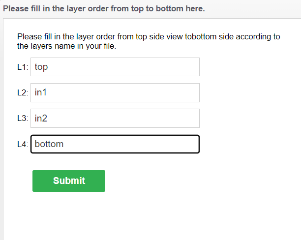
Next the site will ask you to name the 4 layers of the board, Do as shown in the following picture
![]()
I benefitted from PCBWay's assembly service as there a Lot of Small SMD parts on my board, on both sides that I don't feel comfortable assembling by hand, so you can choose to do so by scrolling down and checking the "Assembly Service" section, you can either input all the parameters or, PCBWay will do that for you once you upload the BOM and xyz files.
After submitting all the files, you will have to wait 24hrs for engineering audit which of course, this board passes, Due to the current chip shortage, you might be contacted by the support team after the audit informing you that some parts are out of stock, PCBWay suggests for each missing part a replacement and inform you of the lead time (usually between 7 and 14 days), I tried to make this board with ICs that were in stock on Mouser, Digikey, and LCSC, but unfortunately there's no way to guarantee the availability of all the components.
Once happy with all the parts, you can then pay for the board manufacturing, assembly and parts costs, and choose your preferred shipping method, in no more than three weeks your assembled board will be at your doorstep.
I even had some wrong parts that I needed to replace after the confirmation of the quotation, by simply contacting the support team they accepted to replace the wrong part with no additional cost :)
Before shipping, PCBway sends you a Picture of your assembled board to confirm if everything is spot on, and sure enough it was, here are the pictures that were sent by their support after the assembly
![]()
![]()
![]()
![]()
![]()
![]()
Finally, here are some pictures of the board taken by me, when it was delivered:
![]()
I highly recommend PCBWay for any PCB manufacturing you need, especially if you would like to get one of this board, you can find the files in this blog under the "files section".
-
Inside the Robot
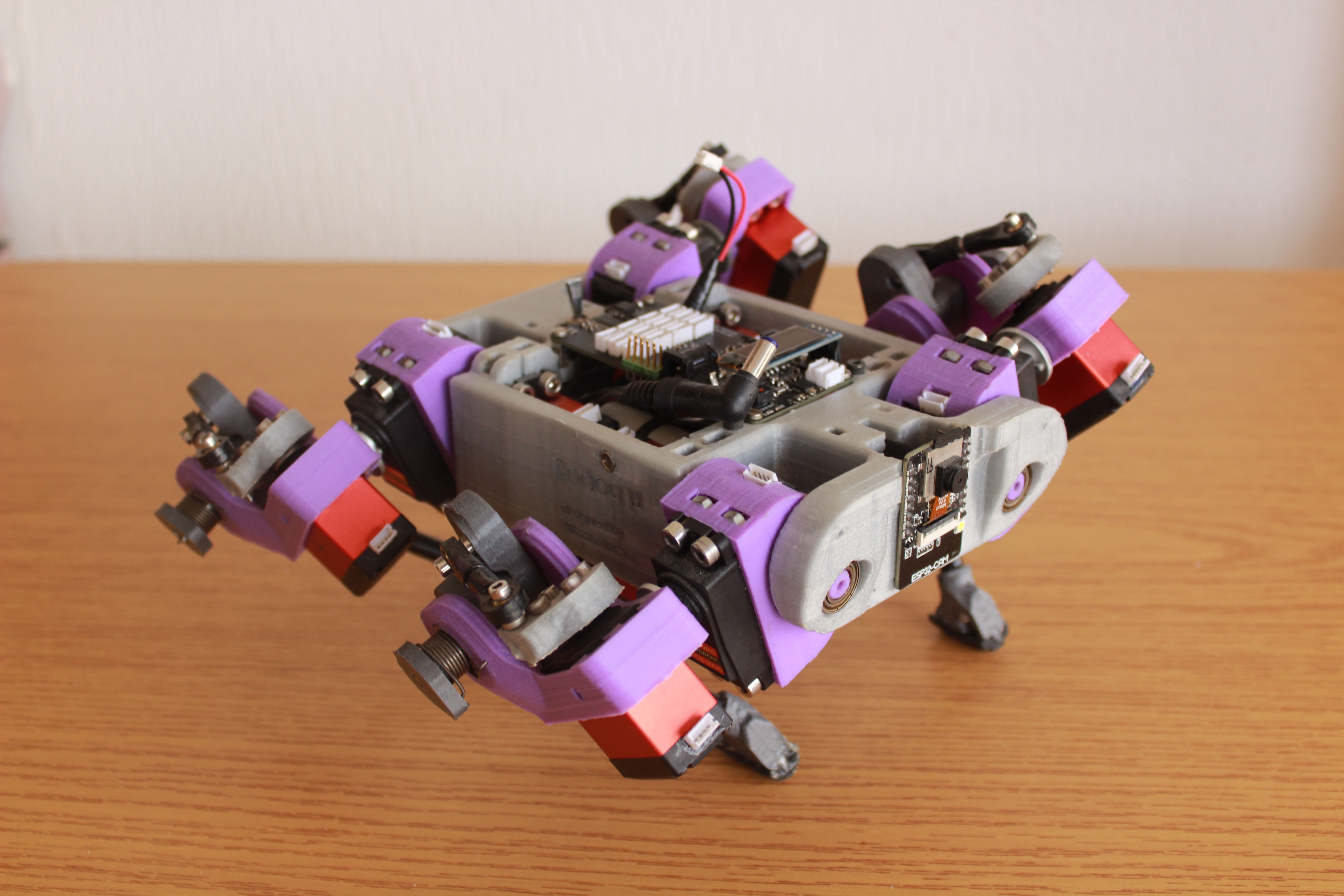
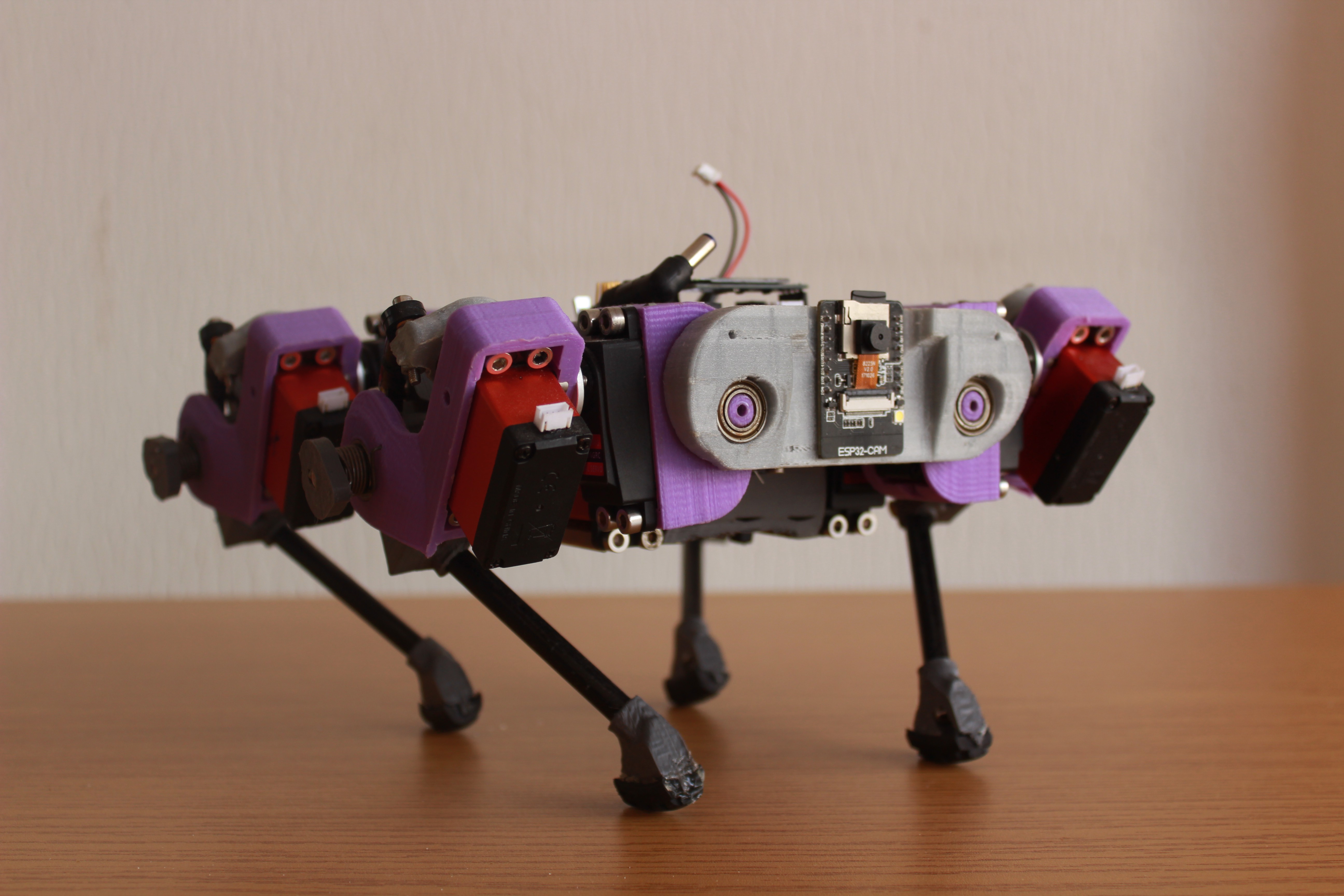
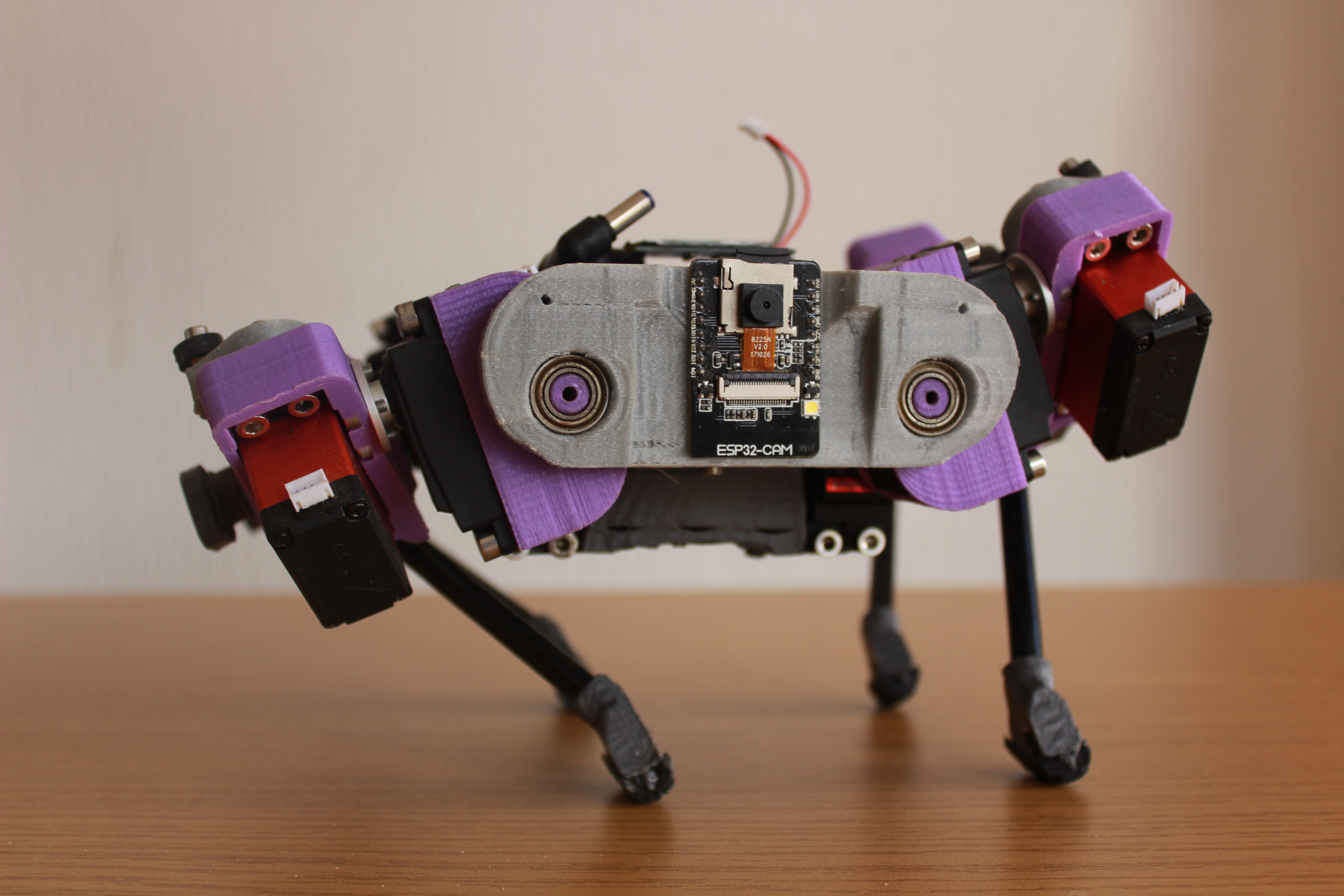
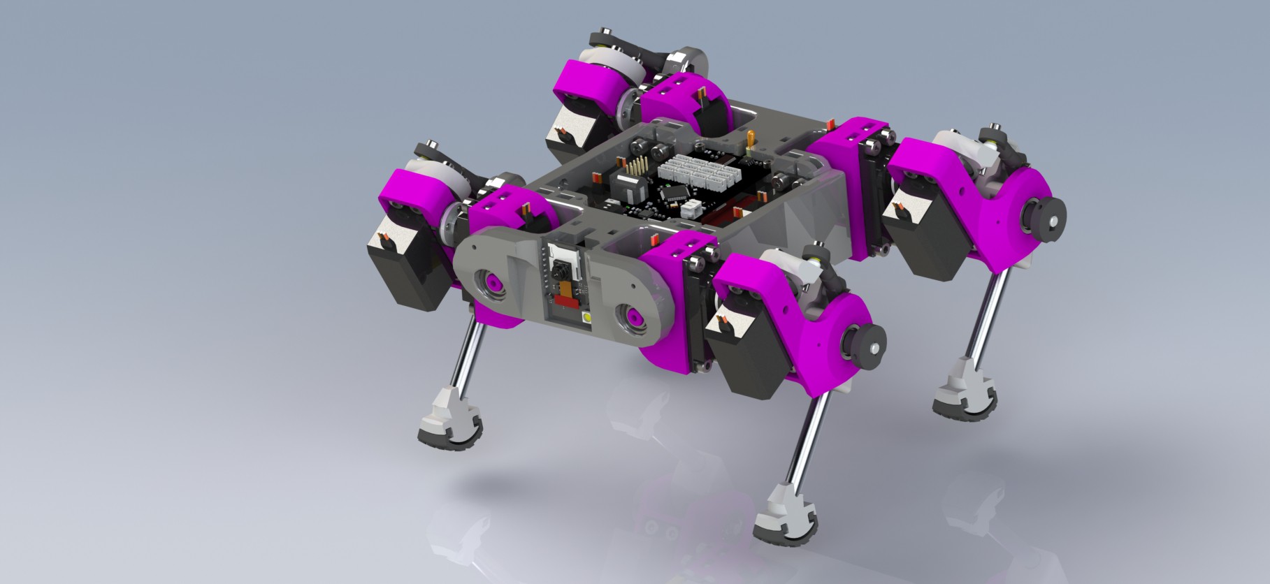
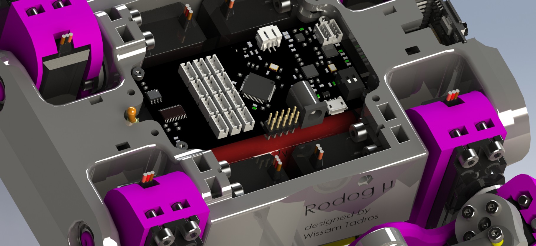
07/13/2022 at 11:06 • 0 commentsLet's take a closer look at what's inside the robot ;)
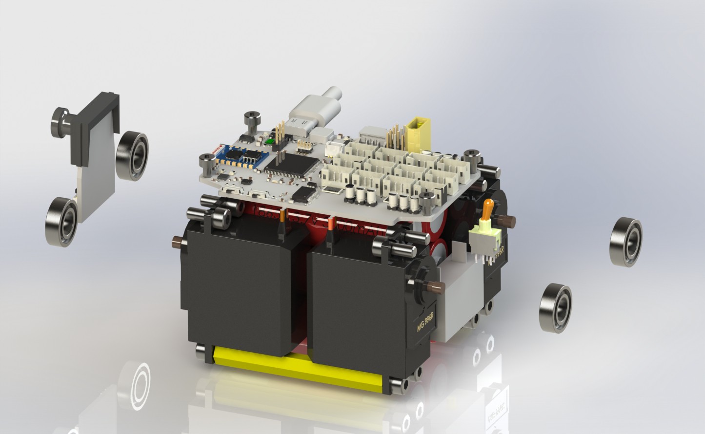
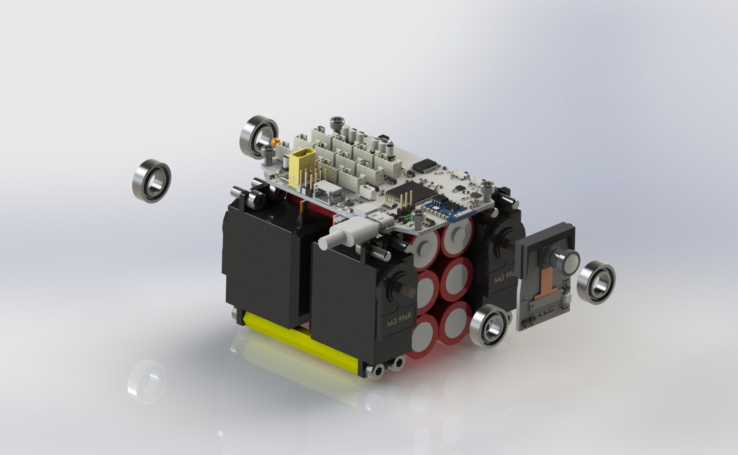
Here are two renders without the chassis part and covers, you can see how compact everything is!
I made sure to have everything symmetric as to get a center of gravity in....well the center!
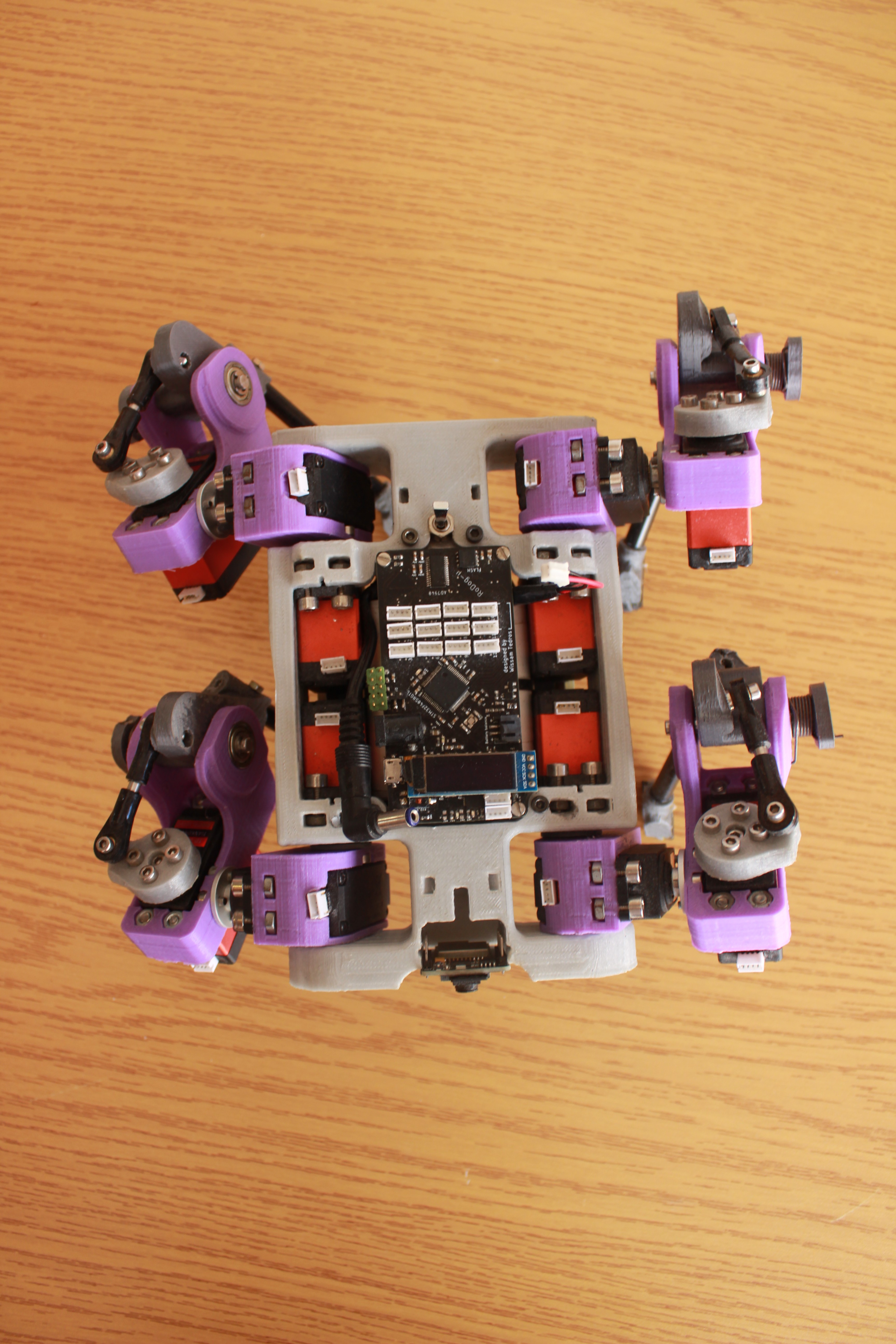
concentrated mass is always a good idea, and as compact and stressful to assemble as it may seem, it's actually pretty easy to do so, the batteries are fixed to a bottom part that is secured with 2 bolts and could be removed by simply disconnecting them form the board and the switchYou can see that there's only one board inside the robot, the mother board, no power distribution stuff, no extra breakouts, just the motherboard, which might be both a blessing and a curse, having a logic board connected to a power distribution board might be a safer system, but space is money in my case. Everything I need is one the board, and there's a blog on that, make sure to check it out!
The battery power doesn't just connect to the board, there is a 6.3A fuse, and 10A manual switch before that, to ensure security, the load switch on the board is good for up to 9A!
![]()
![]()
The servos for the Hip joints are nicely tucked inside the chassis, optimizing the usage of the space available and giving the Robot an overall shorter length.
Consider this quick blog as an introduction to what I'm working on currently, which is a full assembly manual of the Robot, with exploded views of the assemblies and annotations!
I'm also working on a render that has some open source quads lined up together, I'm reaching out to their creators, if you designed a quadruped and have no problem sharing the STEP and would to see it, Private message me and I'll add yours to the render!
-
New Mother-Board
07/10/2022 at 14:25 • 0 commentsAfter overly testing the Last mother board, I listed some issues that lead me to design an optimized version of the mother-board, The new version has the same features of the last one with few improvements.
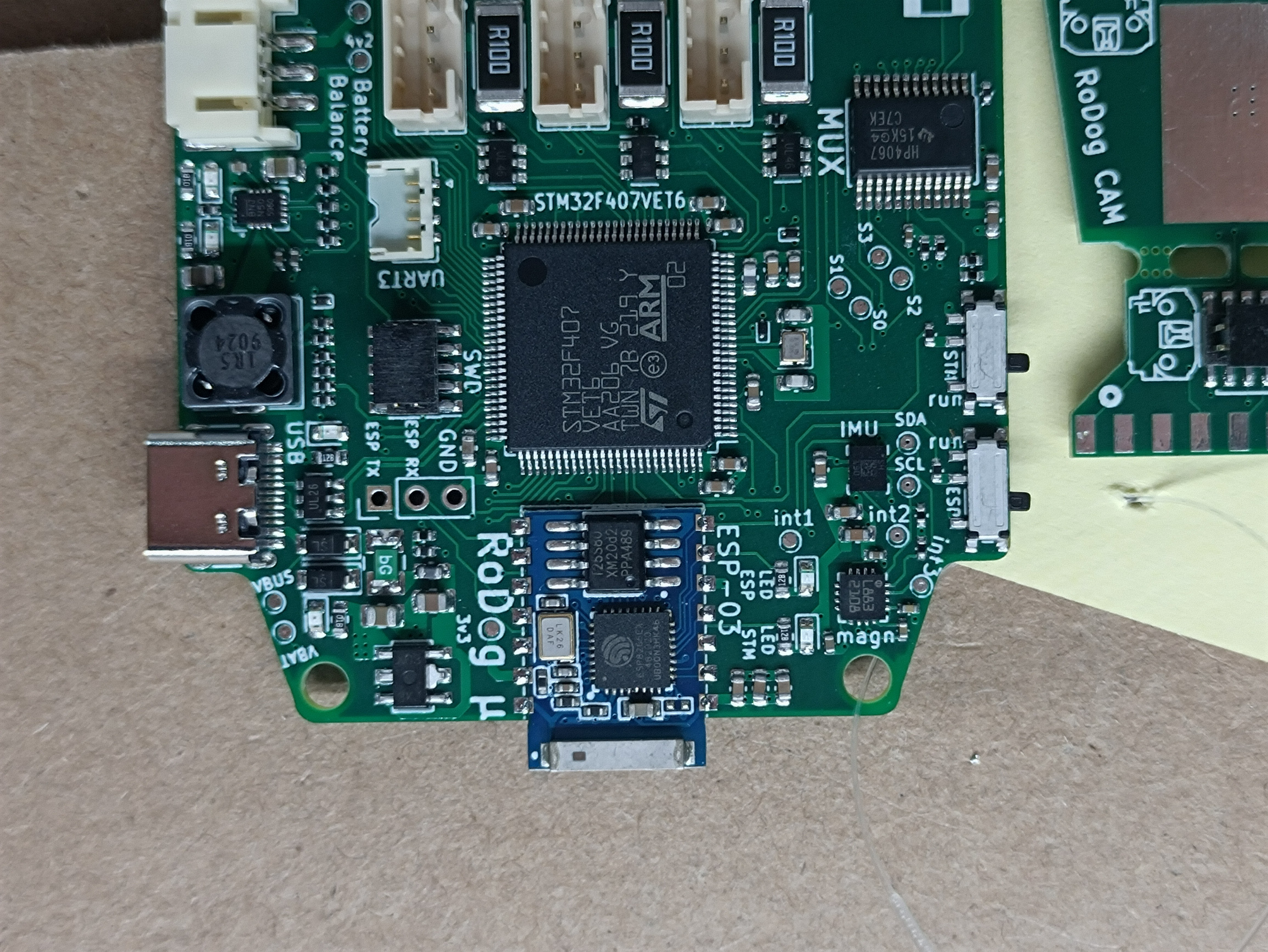
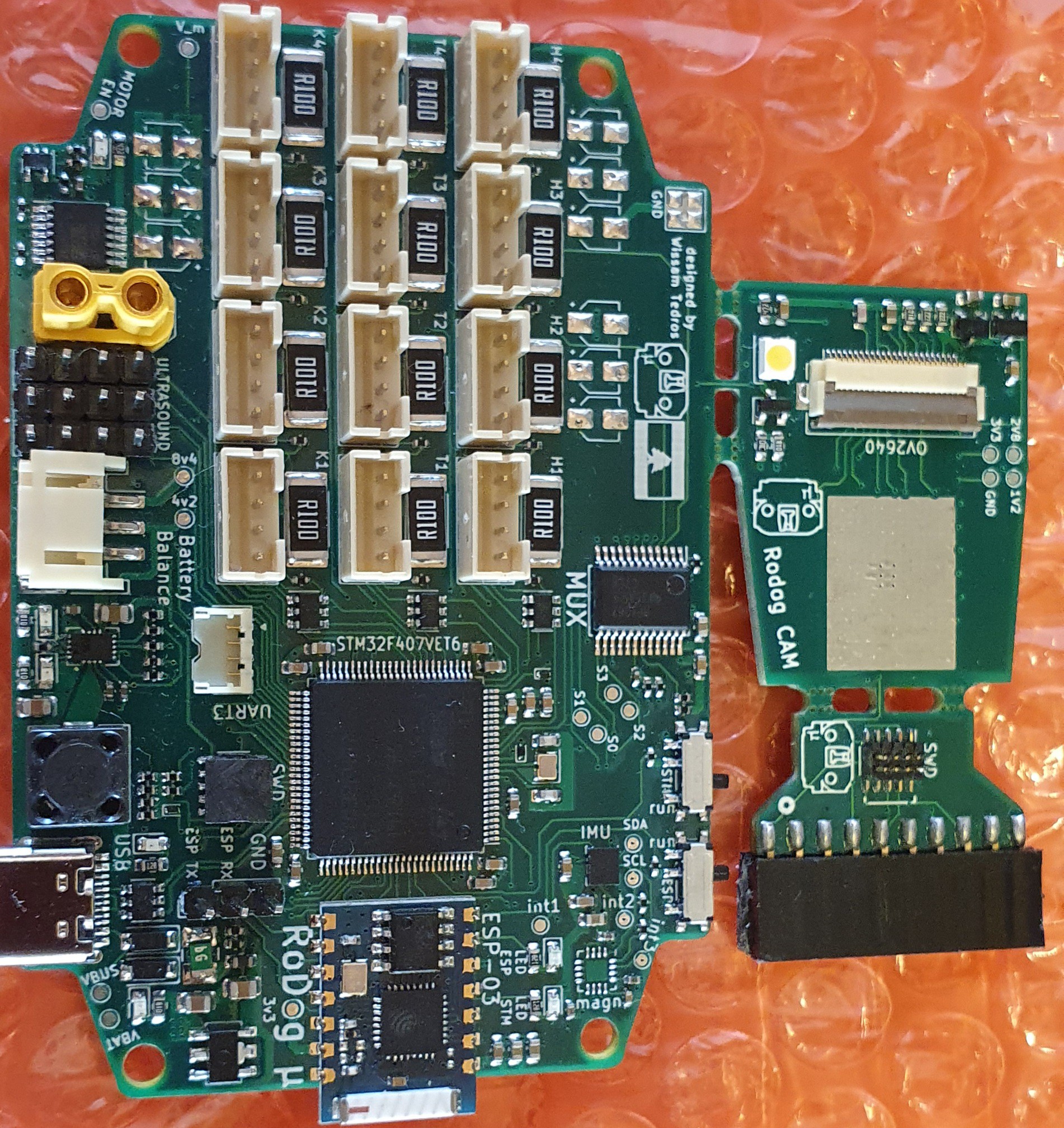
It features: (* New)- *STM32f407vet6 rather than the STM32f405rgt6.
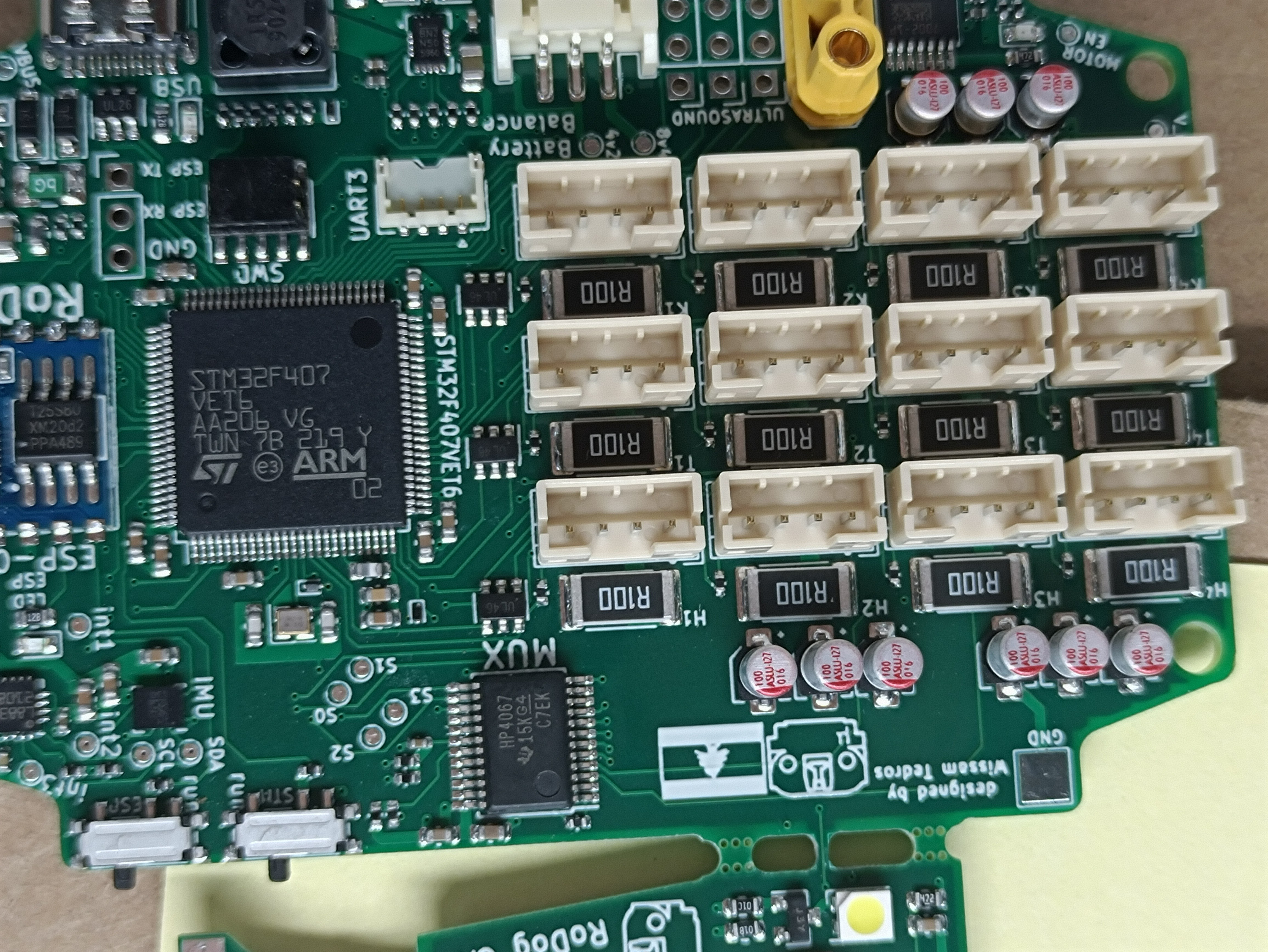
- 12 PWM outputs for the servos
- 12 ADC inputs for position feedback
- 12 current sensing circuits for force estimation feedback
- *lsm6dso32x and hmc5883cl magnetometer working as a 9DOF Inertial measurement unit with interrupt pins attached to the MCU.
- *On-board Esp8266 for AT commands, and UART port exposed for programming it
- *Load switch on the Servo Power, this Load switch is activated by a GPIO and the MCU Reset pin, if the MCU is in Reset mode, the power to the servos is cut-off, this is to remove the random chaotic servo moves when the microcontroller is in reset mode.
- *New IC for battery management, (Charge through USB-C, and Balancing)
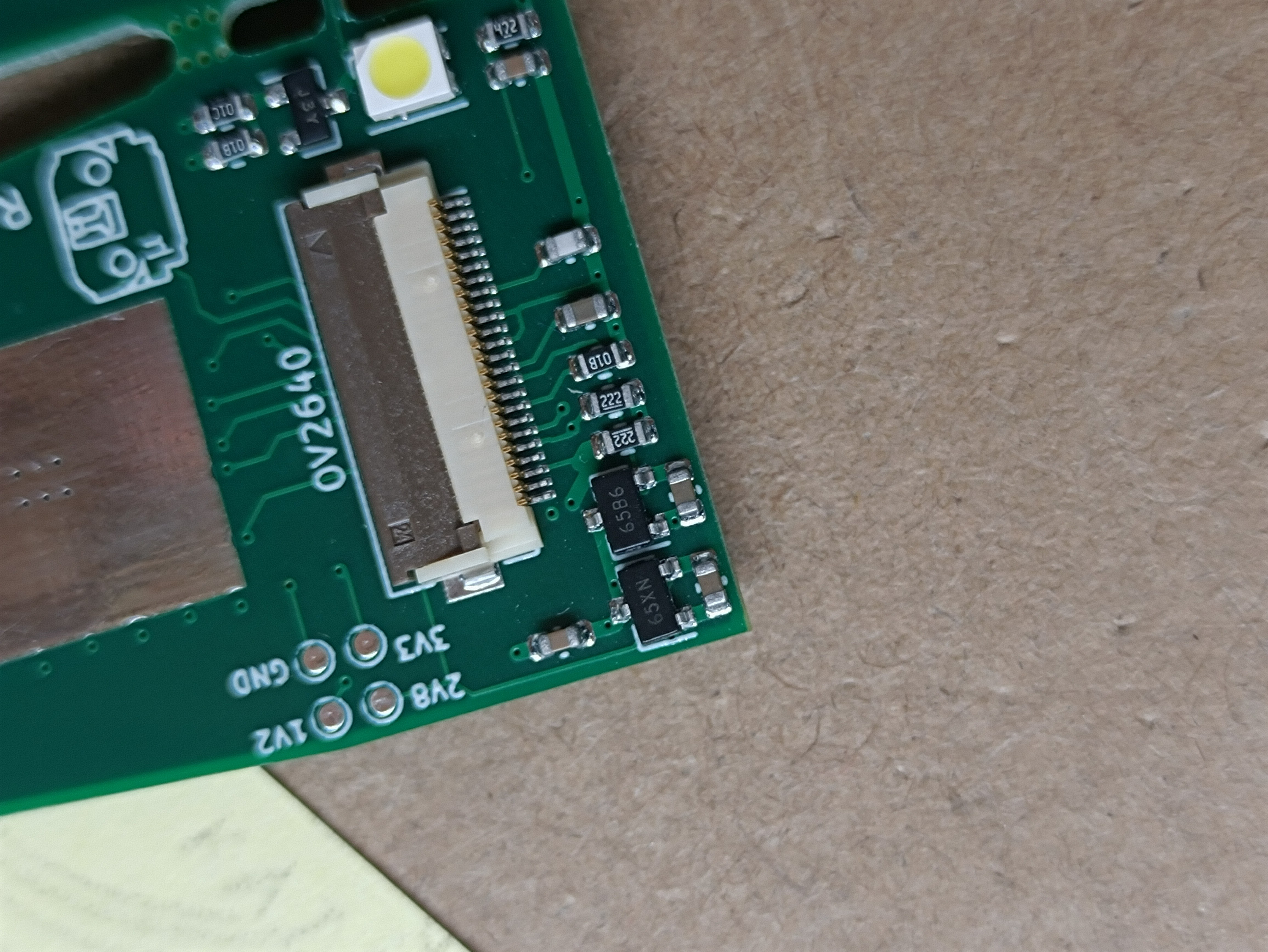
- *DCMI interface and a ov2640 camera breakout
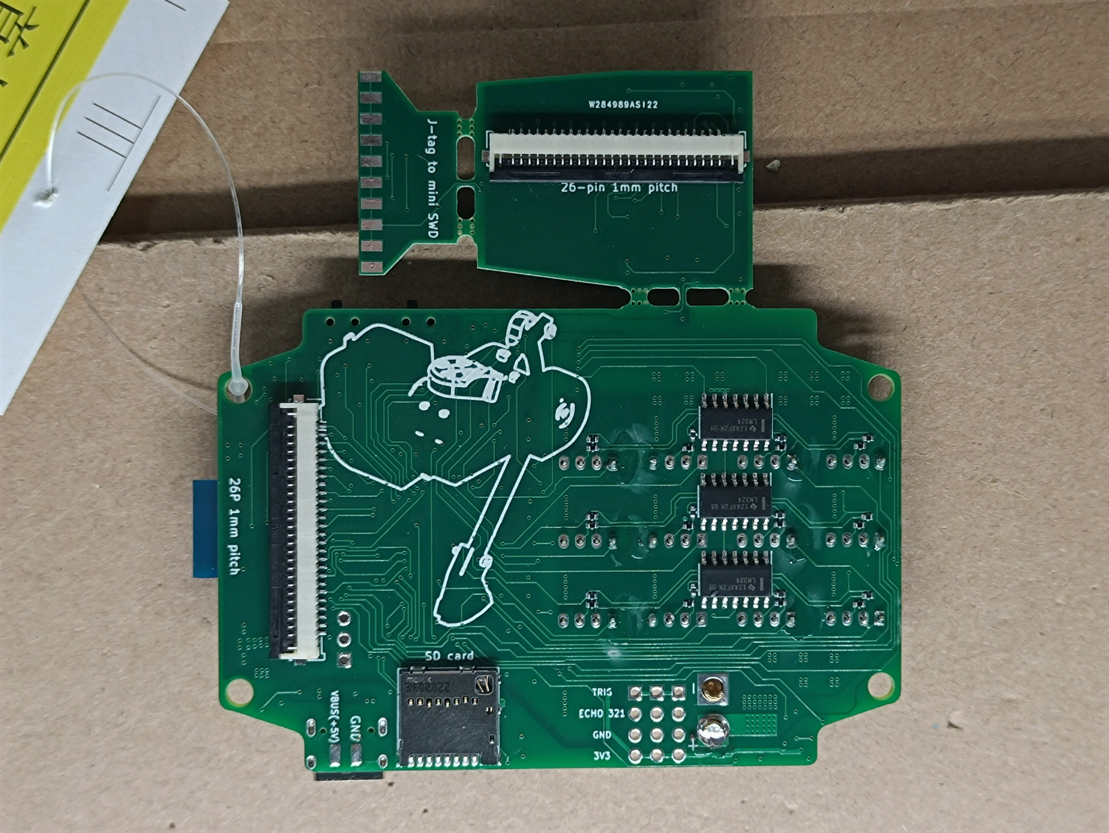
- *SD card with SDIO interface
- *3 Ultra-sound sensors GPIOs with connected Trigger pins
- *UART port exposed for any expansions needed
- *Better current consumption (9~25mA vs previously 20~50mA)
- *All ADC inputs are protected with clamping Diodes and resistors.
- *Better Isolation between the Power planes and the I/Os
- *lots of indicator LEDs and Test-Pads(check the layout + Schematics)
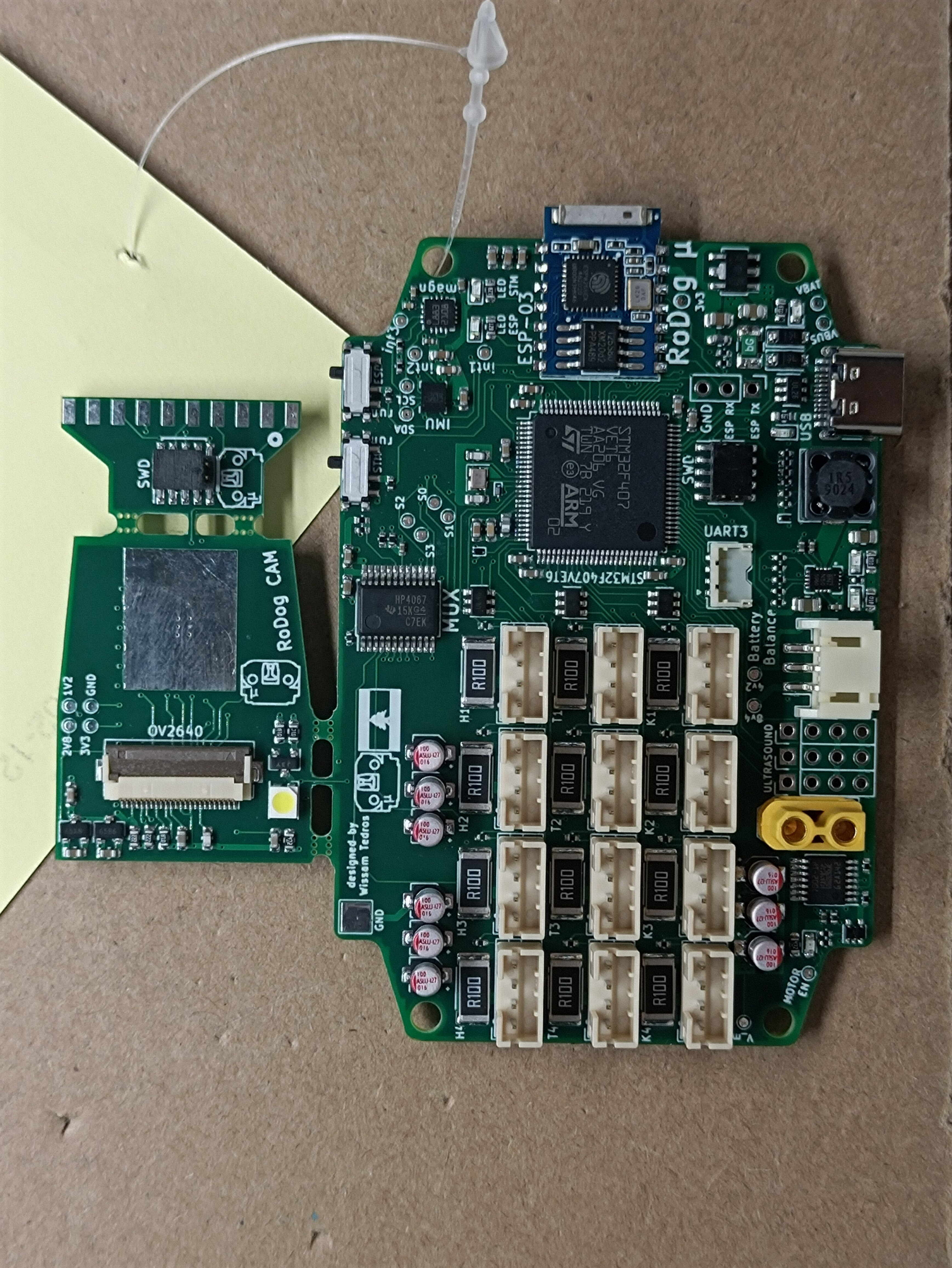
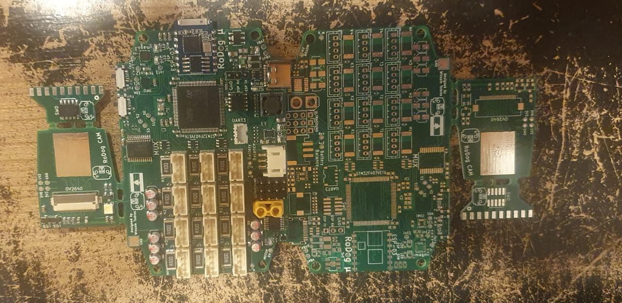
![]()
As you can see, there are 3 boards, the Mother board, the camera breakout , and an ST-LINKV2 to mini SWD breakout, of course, they are meant to be separated
you can Check the schematic and GRBR files in the project files section!
-
Some Pics :)
11/12/2021 at 11:30 • 0 commentsfigured It's about time to take some respectable Pics of the robot, so here goes nothing
![]()
![]()
![]()
![]()
-
Simulation
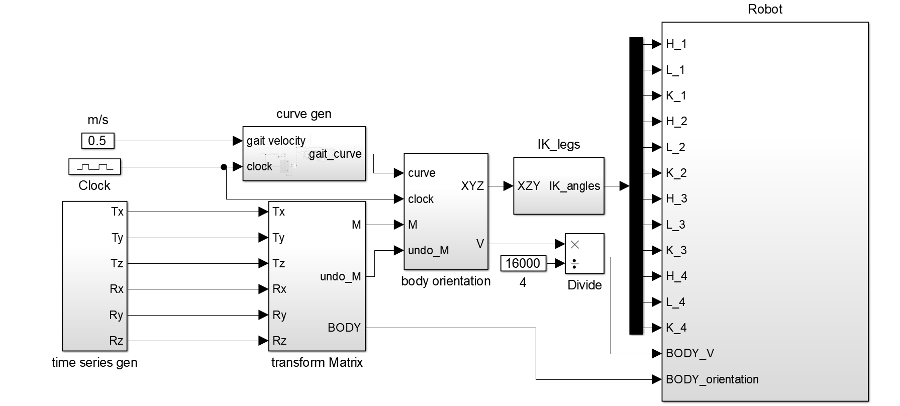
09/20/2021 at 15:50 • 0 commentswith the help of a MATLAB Simulink trial, I managed to animate My CAD assembly, to get a feel of how to manage the inverse kinematic model control on my embedded system.
here is the Block diagram of my Simulink:
![]()
A Bezier curve is generated from 13 data points, to generate the path of the end effector as the robot walks, this curve widens as the velocity of the body increases. it is also rotated based on the "heading" angle, that dictates the walking direction of the robot.
this curve is then sent to the "body orientation" block, where, to handle the rotation of the local frames, to keep the end effector static to the world frame.
finally, the XYZ of each end effector is sent to the Inverse kinematic solver for the leg, that outputs the 3 necessary angles for each joint (H , L and K).
I have plans to make a DXF to timeseries converter, to make the robot move along the path drawn, but that is a future non-primary goal. I still have some control to do for the body velocity, as I don't have a convincing feedback of it.Here are some of the outputs I got with this block diagram:
![]()
![]()
![]()
![]()
![]()
![]()
![]()
![]()
-
Current Mechanical design
06/14/2021 at 23:10 • 0 commentsI think this is what I'll settle for as a final-ish mechanical design, it is as compact as I wanted it to be, main body is 20x10x5cm, it has some vibrations, I'm suspecting the backlash in the RC servo, I have some thoughts to add light spiral springs to solve that. I'm currently animating the Model using Simulink Simscape Multibody, once happy I'm going to apply my control loop to the embedded system I made.
![]()
![]()
![]()
![]()
![]()