danjovic
-
PS/2 and USB in (fallback mode) tests
07/09/2021 at 14:31 • 0 commentsFinally got some time to record some videos of the keyboard adapter working in both native PS/2 keyboard and with a USB keyboard on PS/2 fallback mode.
Box Opened Native PS/2 keyboard
USB in PS/2 fallback mode
-
Rise time with pullups
04/10/2021 at 15:00 • 0 commentsI was intrigued with some interrupt response time figures. Theoretically I should have figures slightly over 1us (and indeed I have) but sometimes the response time scaled up from 2.0 to 3.5 us.
Then I realized that the longest response times were all on rising edges!
What happens is that I am using DDR register to emulate open collector outputs and for that reason the fall times are within expected, but the rise time will depend upon the R-C constant formed by the pullup resistors on the MSX computer along with the parasitic capacitance (predominantly from the wiring).
I should have seen that before!
-
"Ported" the code to Plain C
04/10/2021 at 00:47 • 0 commentsI have just ported the source code toplain C which required me to practically rewrite the PS/2 keyboard library. Besides that it was necessary to create the prototype of various functions and a main() function
int main (void) {
   setup();
   for (;;) loop ();
}
It was possible of course to rename the loop() function and call setup() from inside.
Also added a makefile. It was necessary to change one DLL (msys-1.0.dll) to make it possible to compile the code in windows 10 .
The last modification was to force the USART to turn off, otherwise the pins PD0 and PD1 would not respond to the writes.
UCSR0B = 0; // disable USART -
Basic Release
04/09/2021 at 04:10 • 0 commentsBasic Release is ready on GitHub, developed on Arduino IDE. I should migrate to plain C code now that I have finished to debug my own PS/2 kebyboard library.
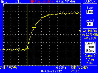
By the way I spent some time to find something that now seems obvious but hard to observe on the logic analyzer that is the rise time of the wired or connections for the PS/2 keyboard:
In a given moment during the beginning of the communication with the keyboard it is necessary to release the CLOCK line then wait for the keybard to pull down the CLOCK line.
When that operation is done on the ps2.h library, there is no explicit delay after releasing the line, because the Arduino (wiring) DigitalWrite command takes a while to process.
  golo(_ps2clk);  _delay_us(300);
  golo(_ps2data); _delay_us(10);
  gohi(_ps2clk);                  // start bit
	while (digitalRead(_ps2clk) == HIGH); /* wait for device to take control of clock */
But the line takes some time to recover, 440 ns from 0 to approximately 3.0 Volts (positive threshold for the ATMega328):
To correct that problem I have added a 5 microseconds delay after the release of the CLK line to give such line some time to recover.// 2) Bring the Data line low. dropDAT(); _delay_us(10); // 3) Release the Clock line. releaseCLK(); _delay_us(5); // give some time for the line to raise // 4) Wait for the device to bring the Clock line low. waitCLKfall();Worth to mention that the functions above are indeed macros dealing directly with the microcontroller registers.
// Hardware definition #define DAT_DDR DDRB #define DAT_PIN PINB #define DAT_PORT PORTB #define DAT_BIT 0 #define CLK_DDR DDRB #define CLK_PIN PINB #define CLK_PORT PORTB #define CLK_BIT 1 #define dropDAT() do { DAT_DDR |= (1 << DAT_BIT); DAT_PORT &= ~(1 << DAT_BIT); } while(0) #define dropCLK() do { CLK_DDR |= (1 << CLK_BIT); CLK_PORT &= ~(1 << CLK_BIT); } while(0) #define releaseDAT() do { DAT_DDR &= ~(1 << DAT_BIT); DAT_PORT |= (1 << DAT_BIT); } while (0) #define releaseCLK() do { CLK_DDR &= ~(1 << CLK_BIT); CLK_PORT |= (1 << CLK_BIT); } while (0) #define readDAT() (DAT_PIN & (1 << DAT_BIT)) #define readCLK() (CLK_PIN & (1 << CLK_BIT)) // #define waitDATrise() do {} while (!readDAT()) #define waitDATfall() do {} while ( readDAT()) #define waitCLKrise() do {} while (!readCLK()) #define waitCLKfall() do {} while ( readCLK()) -
Shrinking the ISR
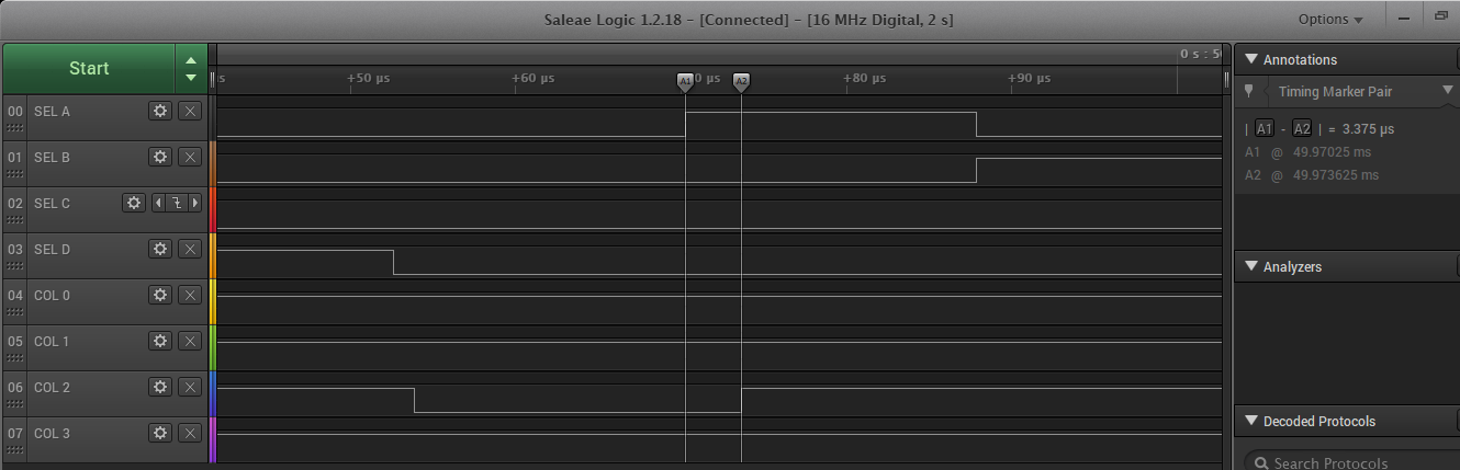
04/06/2021 at 02:37 • 0 commentsit was necessary to shrink the pin change irq to fit within the timing necessary to attend the Z80.
![]()
Doing the Math I should be spending 1us to output the code, counting the IRQ latency, but I have seen some figures of up to 3.25us which is barely enough.
It should be possible to increase this margin by changing the crystal to 20MHz, but I am testing with an arduino board (at 16MHz).
The code uses some tricks to save clock cycles like saving the registers r26 and r27 on general purpose I/O registers available in ATMega328, and using the __zero_reg__ to store the flags
volatile uint8_t zero = 0;
ISR (PCINT1_vect, ISR_NAKED) {
  asm volatile (                     // 7 instrucoes de latencia até aqui
    "in __zero_reg__,__SREG__ \n\t"  // 1 Salva registrador de Status
    "out %[_GPIOR1],r26\n\t"         // 1 salva registro em 1 ciclo
    "out %[_GPIOR2],r27\n\t"         // 1 salva registro em 1 ciclo

    "ldi r27,hi8(Keymap)\n\t"        // 1 Ponteiro X = endereço de Keymap
    "in r26,%[_PINC] \n\t"           // 1
    "subi r26, lo8(-(Keymap)) \n\t"  // 1
    "ld 26,X \n\t"                   // 2 lê coluna correspondente do mapa de teclas
    "out %[_DDRD] ,r26 \n\t"         // 1 escreve na porta B da PPI
                                     // até aqui 16 instruções (1us @16Mhz)
    "in r26, %[_GPIOR1] \n\t"
    "in r27, %[_GPIOR2] \n\t"

    "sbi %[_PCIFR],1 \n\t"           // reset interrupt bit

    "out __SREG__,__zero_reg__ \n\t" // restaura registrador de Status
    "lds __zero_reg__, zero \n\t"
    "reti \n\t"

    ::[_PINC] "I" (_SFR_IO_ADDR(PINC)  ),
    [_DDRD]   "I" (_SFR_IO_ADDR(DDRD)  ),
    [_PORTB]  "I" (_SFR_IO_ADDR(PORTB) ),
    [_GPIOR1] "I" (_SFR_IO_ADDR(GPIOR1)),
    [_GPIOR2] "I" (_SFR_IO_ADDR(GPIOR2)),
    [_PCIFR]  "I" (_SFR_IO_ADDR(PCIFR) )
    );

}