-
Wiring
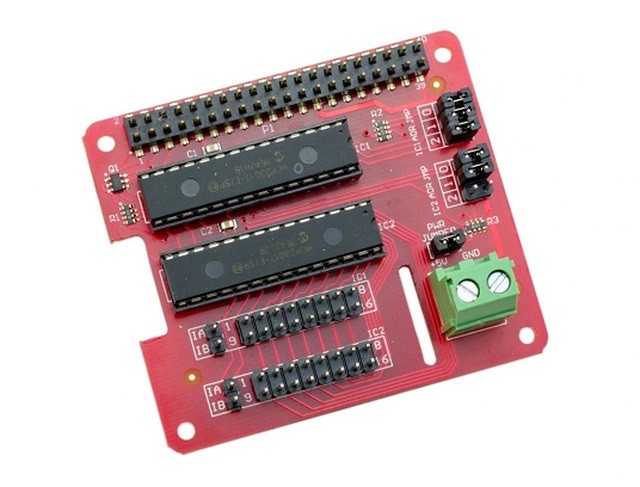
04/15/2021 at 21:13 • 0 commentsWell my port extender hat finally arrived so I got busy wiring the front panel to the Raspberry Pi via the extender.
![]()
The port extender came with standoffs, so I used two diagonal corner holes on the Raspberry Pi to mount it to the bottom frame, and the opposite two corner holes with the standoffs to support the hat. Seems reasonably solid.
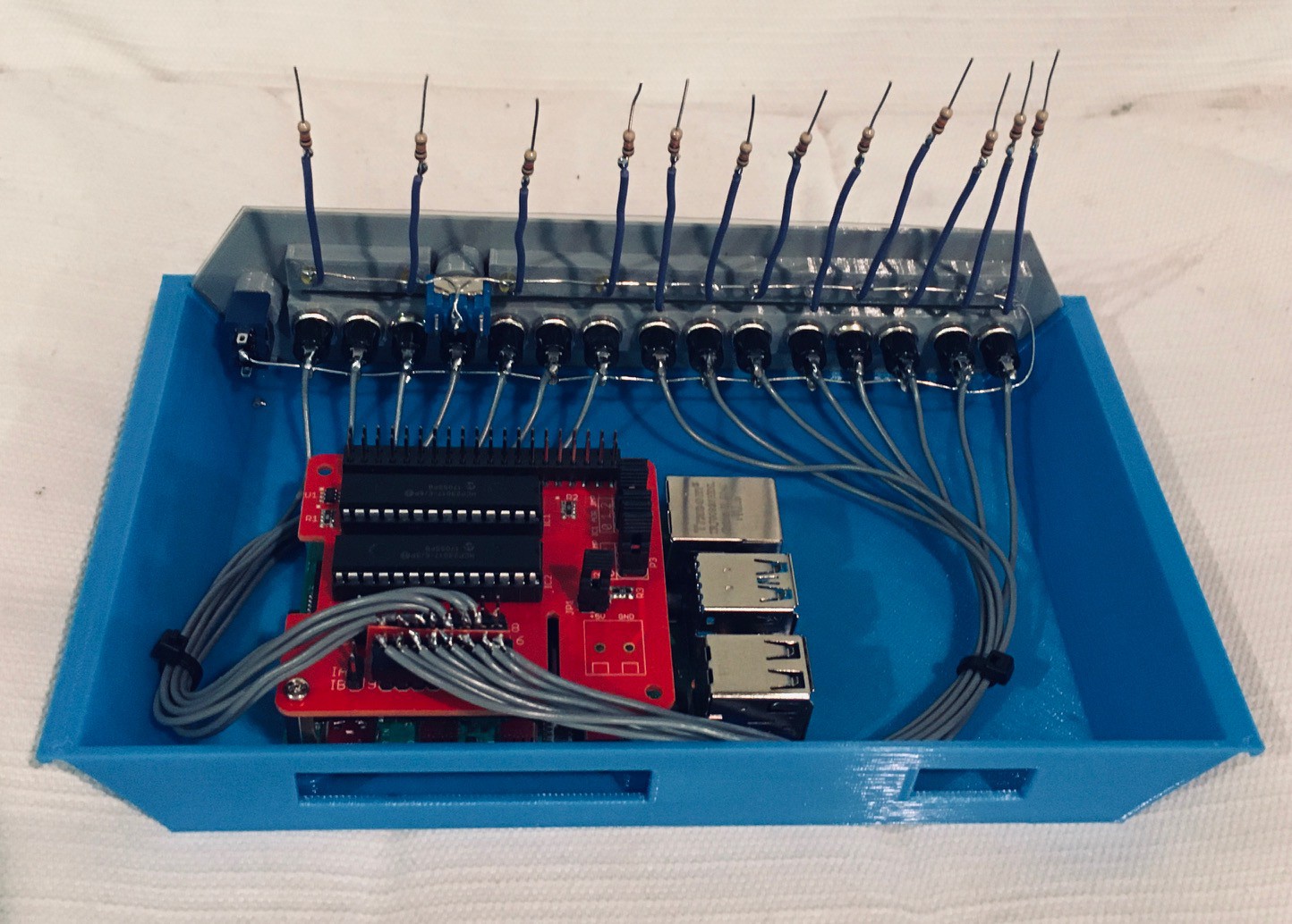
In the following photo I'm about half done. A ground wire has been routed to all of the front panel components, the fifteen push buttons have been connected to the hat, and the twelve LEDs have a short wire with a limiting resistor attached. The resistors are 10k to keep the brightness down.
![]()
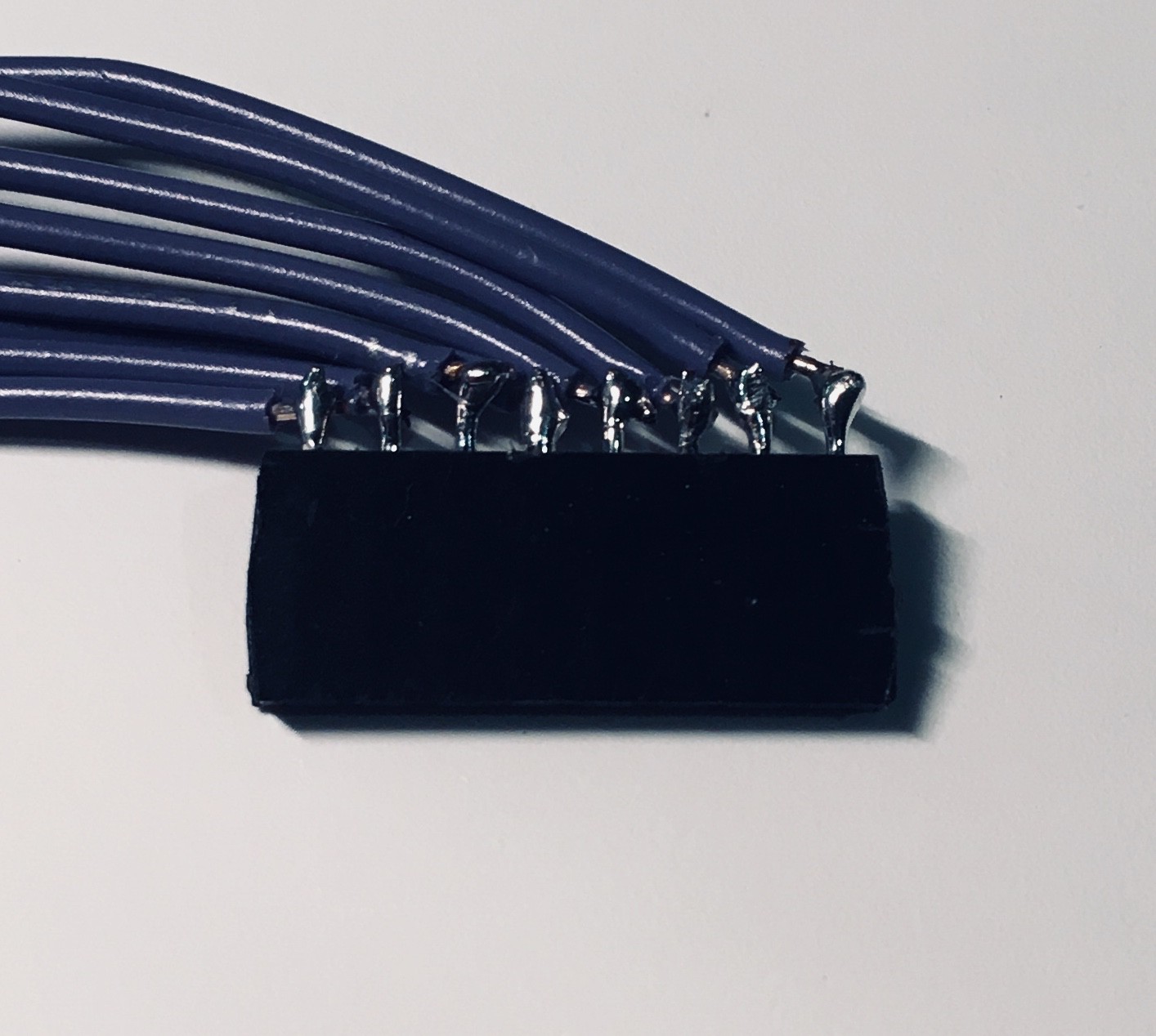
I used female headers to connect the front panel lights and buttons to the extender. Because there wasn't a lot of head room with the top frame on, and space between the male headers on the board, I had to angle the wires as in the photo below.
![]()
It was a little tight, and as I soldered the wires onto the the header I kept asking myself why I hadn't designed a PCB for the front panel. At the end of the day though it worked out OK.
![]()
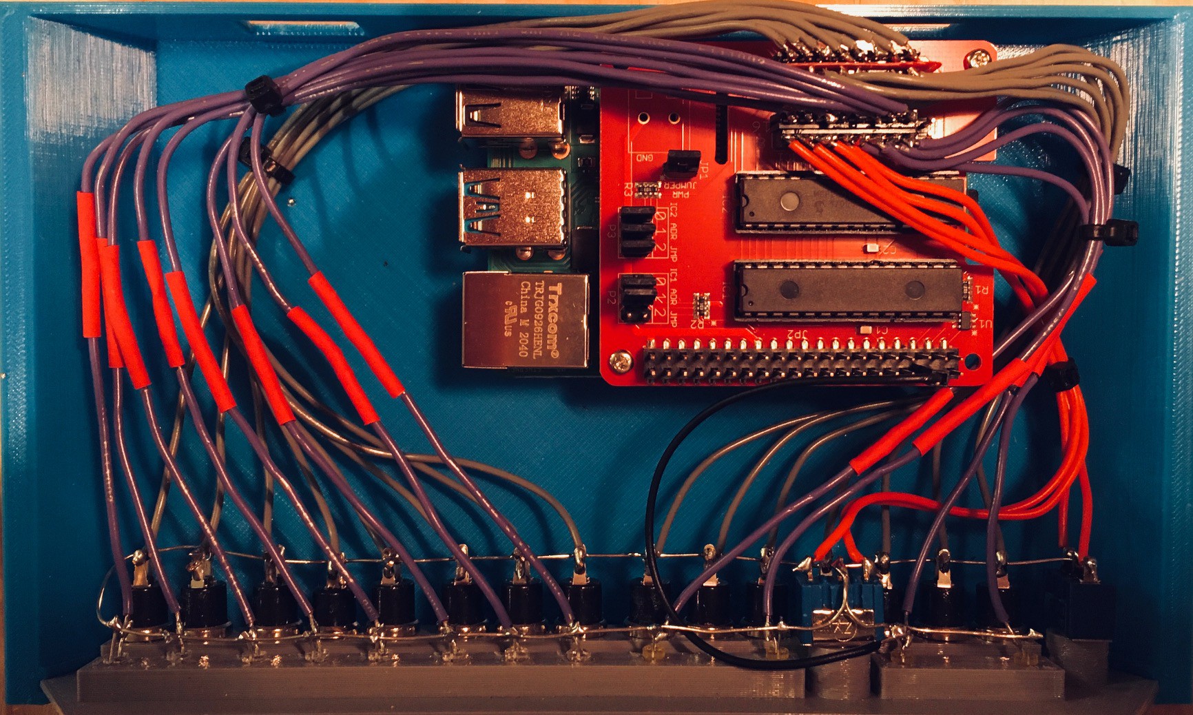
The red heat shrink protects the "inline" limiting resistors for the LEDs. A few cable ties and my KENBAK-2/5 is ready to go.
Next step is to write the code to manage the front panel and integrate it with my Emulator.
-
Is Emulation Really the Sincerest Form of Flattery?
04/11/2021 at 19:29 • 0 commentsThe Emulator for my KENBAK-2/5 Reproduction simulates in software the operation of the 132 integrated circuits that made up the original KENBAK-1's hardware. It accepts as input a 256 byte array that represents the entire block of memory that was in a KENBAK-1 and executes the instructions encoded into those bytes until a HALT instruction is encountered.
While an Assembler takes the symbolic representation of an instruction like LOAD A,1 and converts it into two byte codes 0x13 and 0x01, the emulator recognizes that 0x13 means load the A register with the byte that immediately follows the op code being executed (0x13) and alters the value of the A register to be a 1.
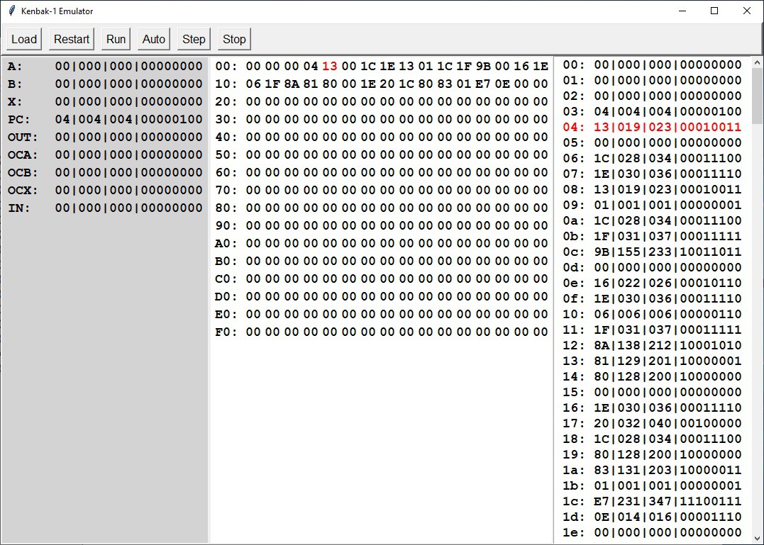
So here is a picture of my KENBAK-2/5 Emulator loaded with the byte codes produced by running my Assembler on the Fibonacci sequence program from the previous log entry.
![]()
On this screen we can see:
- Left - The values of nine special memory locations in the KENBAK-1;
Name Address Usage A 000 A register. B 001 B register. X 002 C register. PC 003 Program counter. OUT 129 Maps to front panel data display lamps. OCA 130 Overflow/Carry bits for A register. OCB 131 Overflow/Carry bits for B register. OCX 132 Overflow/Carry bits for C register. IN 255 Maps to the front panel data input button - Middle - A hex based overview of the 256 bytes of KENBAK-1 memory.
- Right - A more detailed view of the memory bytes in hex, digital, octal, and binary representations.
Here is a short video of the Emulator in action.
- Left - The values of nine special memory locations in the KENBAK-1;
-
A Minimal Viable Working Assembler
04/11/2021 at 15:50 • 0 commentsI'm still waiting on a port extender hat for my Pi 4 so I have had a lot of time to work on the KENBAK-2/5 software. I started with the Assembler based on the outline that I posed in the previous log. It is written in Python using Tkinter for the UI with no external libraries. You can find this early version of the program in the GitHub link associated with this project.
This stand alone Assembler component will eventually be incorporated into a simple IDE for the KENBAK-1.
Here is a short video of the Assembler in action.
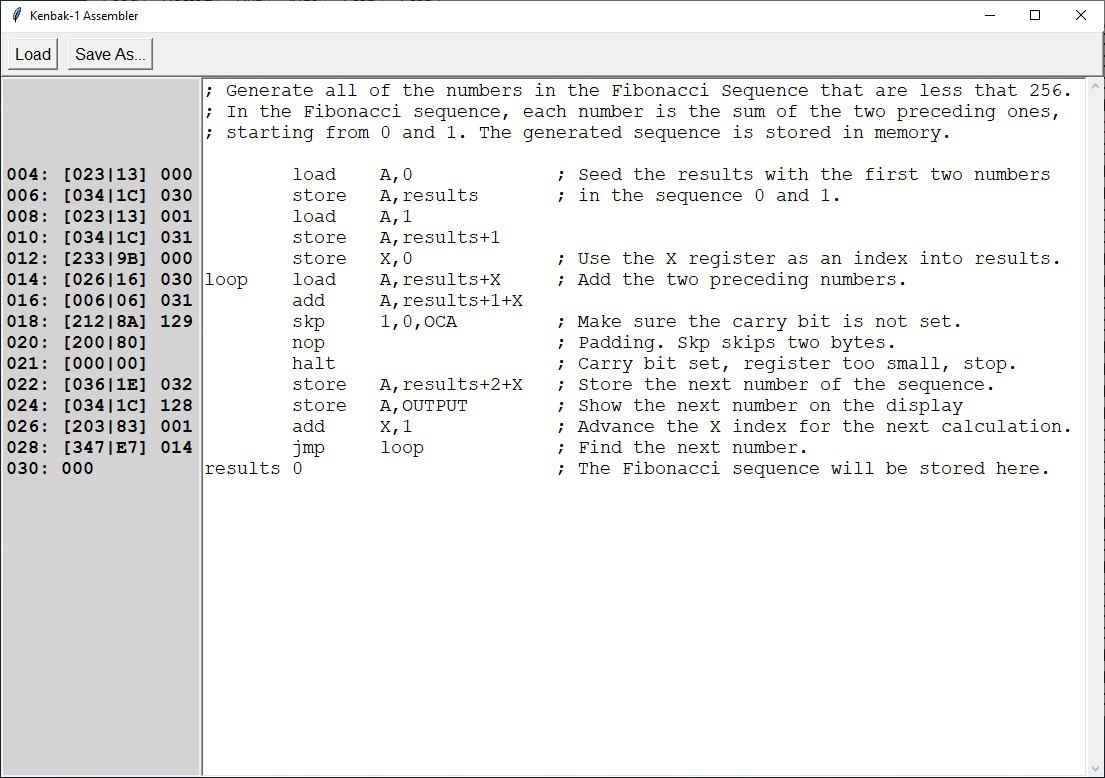
And a screen shot of the Assembler with the Fibonacci program loaded.
![]()
Here we can see:
- labels and labels with offsets (+1, +2)
- pre-defined memory locations (OUTPUT, OCA)
- direct and indexed addressing modes
- constants
With the Assembler done I wrote a number of small programs to exercise the various op codes and addressing modes. These I verified by manually checking the byte codes produced against the documentation in the KENBAK-1 Programming Reference Manual. This is pretty tedious work so I was anxious to get on with the next step, an Emulator.
-
Writing an Assembler
04/06/2021 at 02:06 • 0 commentsThe KENBAK-1 was intended for the education market. As a result the documentation is excellent. The Programming Reference Manual has all of the information necessary to construct an Assembler for the KENBAK-1 computer:
- Memory Structure and Addressing - The KENBAK-1 is an 8-bit computer with memory of 256 bytes.
- Special Memory Locations - Nine memory locations are used for special purposes.
- A Register - Primary register for arithmetic unit. (000)
- B Register - Secondary register for arithmetic unit. (001)
- X Register - Used for Indexed address mode and arithmetic. (002)
- P Register - Program instruction address. (003)
- Output Register - Maps to the front panel lights. (128)
- Overflow and Carry for the A Register. (129)
- Overflow and Carry for the B Register. (130)
- Overflow and Carry for the X Register. (131)
- Input Register - Maps to the front panel data buttons. (255)
- Number Representations - Including unsigned and signed 8-bit integers and signed fractions.
- Addressing Modes - There are five addressing modes that affect the meaning the second word of an instruction:
- Immediate - is the operand.
- Memory - is the address of the operand.
- Indirect - is the address of the address of the operand.
- Indexed - the contents are added to the X register to form the operand address.
- Indexed Indirect - the contents are used as an address pointer to a second address to which the X register is added to form the operand address.
- Instruction Descriptions - Includes a complete description of the operation of each one and two byte instruction and the bits used for each OpCode variant (addressing modes, register selection, etc.)
The Symbolic Representation of Instructions section of the manual gives some guidance as to the abbreviations to be used and the layout for "written" symbolic KENBAK-1 instructions including how to represent the various addressing modes. For the most part I followed these guidelines. I couldn't however bring myself to use NOOP for the no op instruction (I used NOP) and I felt that +X worked better to represent Indexed addressing mode as opposed to ,X. I had a lot of fun trying to come up with a consistent overall look for the instructions.
So in the end I came up with the following document which I feel represents everything I need to provide in a "minimal viable assembler" (MVA) for my KENBAK-2/5 machine.
Assembler Syntax
================

Instructions
~~~~~~~~~~~~
add    [A|B|X],[constant|address]            ;[I|M|(M)|M+X|(M)+X]
sub    [A|B|X],[constant|address]            ;
load   [A|B|X],[constant|address]            ;
store  [A|B|X],[constant|address]            ;
and    [A],[constant|address]                ;
or     [A],[constant|address]                ;
lneg   [A],[constant|address]                ;

jmp    [A|B|X],[NE|EQ|LT|GE|GT|GLE],address  ;[M|(M)]
jmk    [A|B|X],[NE|EQ|LT|GE|GT|GLE],address  ;

skp    [7|6|5|5|4|3|2|1|0],[0|1],address     ;[M]
set    [7|6|5|5|4|3|2|1|0],[0|1],address     ;

sft    [A|B],[L|R],[1|2|3|4]
rot    [A|B],[L|R],[1|2|3|4]

nop
halt

org    constant                              ;[I]

Directives
~~~~~~~~~~
       org    constant                       ;[I]
label  [blank|instruction|constant]          ;[I]
       constant                              ;[I]

The org directive can appear anywhere to set the starting instruction address
for all instructions that follow. If a constant is not present address 4 is
assumed.

If the OpCode position has an Integer Constant, then the value of that constant
is placed at the current address, and the program counter is advanced by one.

Notes
~~~~~

* Any text appearing after a semi-colon (;) on a line will be considered a
  comment and be ignored.

* All OpCodes, operands, and labels are NOT case sensitive.

* A line of assembly code consists of:
    - whitespace (spaces and tabs) OR an optional label followed by whitespace,
    - an OpCode followed by whitespace,
    - optional comma separated operands.

* Labels must start in column 1 and must begin with a letter. A label can stand
  alone on a line or can be followed by an OpCode or an Integer Constant.
  Labels are used to determine a specific instruction address. An offset can be
  added to a label's value when it is used and is defined by appending a + sign
  followed by an Integer Constant, for example label+3.

* For addresses:
   I     - Immediate (Integer Constant)
   M     - Memory
  (M)    - Indirect
  M+X    - Indexed
 (M)+X   - Indirect Indexed

  A, B, X, and P are reserved address names for the four registers. Any address
  M beginning with a letter is assumed to be a label associated with the actual
  memory address who's value, obtained using the appropriate addressing mode,
  will be used in the operation. Any address beginning with a digit or a dash is
  assumed to be an Integer Constant representing the actual value to be used.

* For jumps:
   NE   - Not equal to zero
   EQ   - Equal to zero
   LT   - Less than zero
   GE   - Greater than or equal to zero
   GT   - Greater than zero
   GLE  - Unconditional (greater or less or equal to zero)

* Integer Constants:
  Decimal - Decimal integers begin with a non-zero digit followed by zero or
            more decimal digits (0–9).
  Octal   - Octal integers begin with zero (0) followed by zero or more octal
            digits (0–7).
  Binary  - Binary integers begin with “0b” or “0B” followed by one or more
            binary digits (0, 1).
  Hex     - Hexadecimal integers begin with “0x” or “0X” followed by one or
            more hexadecimal digits (0–9, A–F). Hexadecimal digits can be
            either uppercase or lowercase.
  Char    - Character values begin with a ' followed by a single character.

  Decimal Integer Constants can have a leading dash (-) to indicate a negative
  number.
I couldn't help but get into the 70's monospaced manual layout documentation vibe.
-
Making the Console
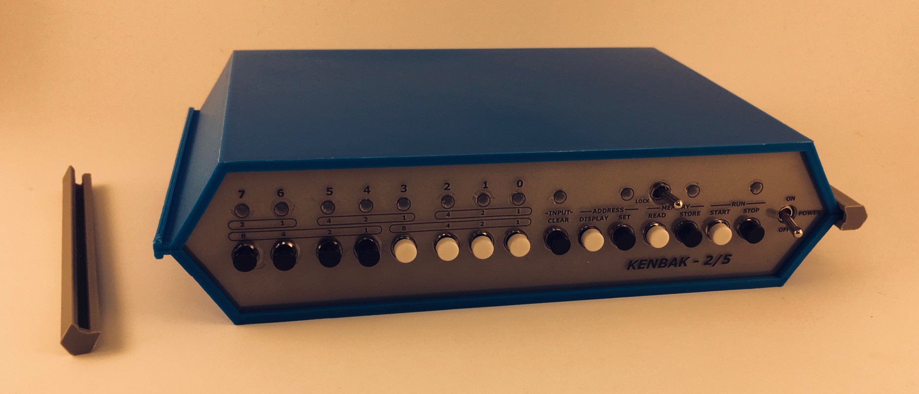
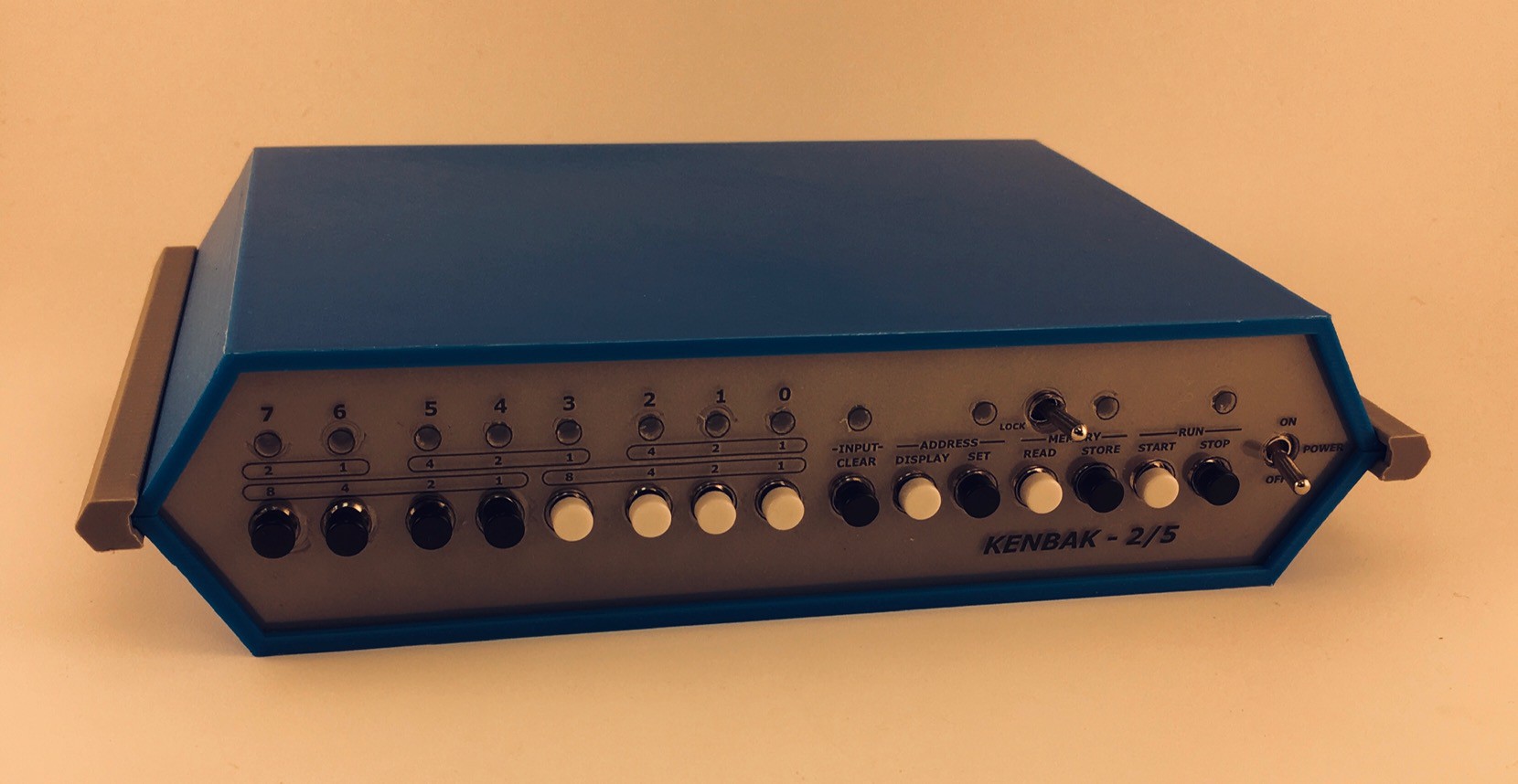
04/05/2021 at 17:56 • 0 commentsThe KENBAL-2/5 console has a 3D printed frame and uses panel mount components. At 40% the size of the original a few compromises had to be made. For one, the great keyboard style push buttons on the front panel of John Blakenbaker's machine proved impossible to replicate. In fact the button positions had to be stretched out horizontally a bit on my reproduction to accommodate the small panel mount push buttons that I did find. Similarly no nice sockets for the panel lamps, just rear mounted 3 mm LEDs.
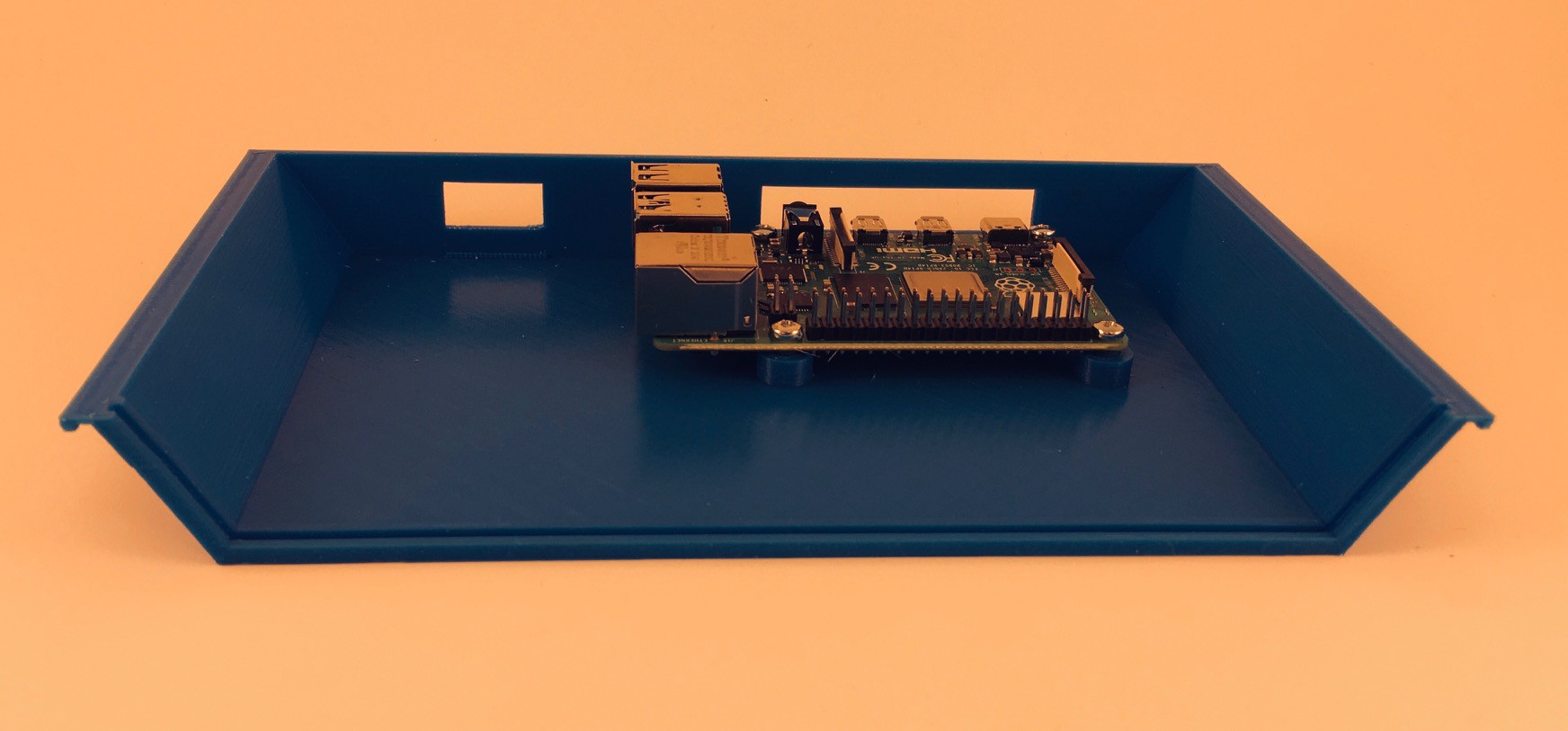
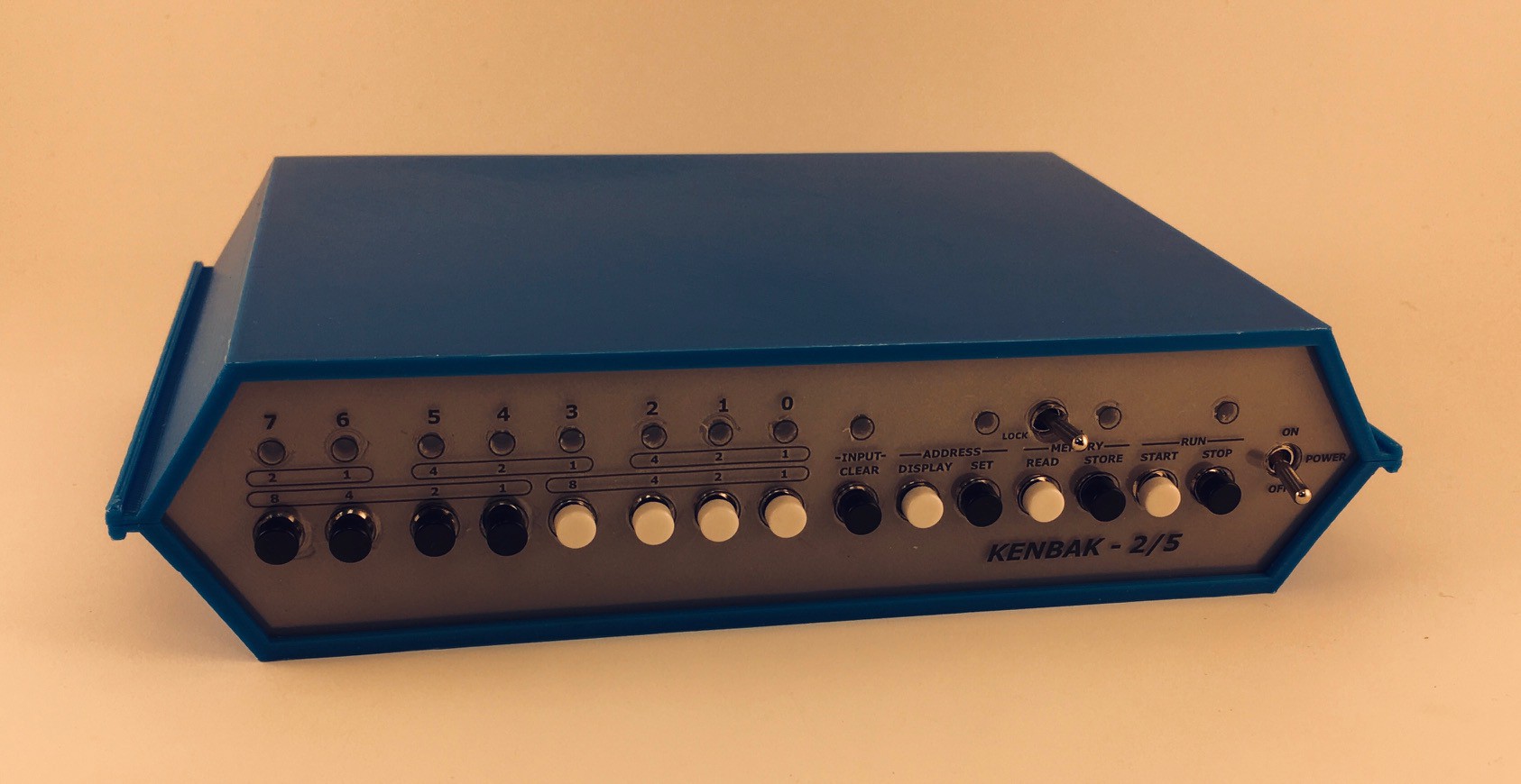
The advantage of the small size is that the pieces will fit on a fairly large selection of 3D printers out there. The shape of the case is a pretty close match to the original as far as I can tell. It is printed in five parts. The bottom has mounting pegs for this project's Raspberry Pi "engine" and cutouts for cabling.
![]()
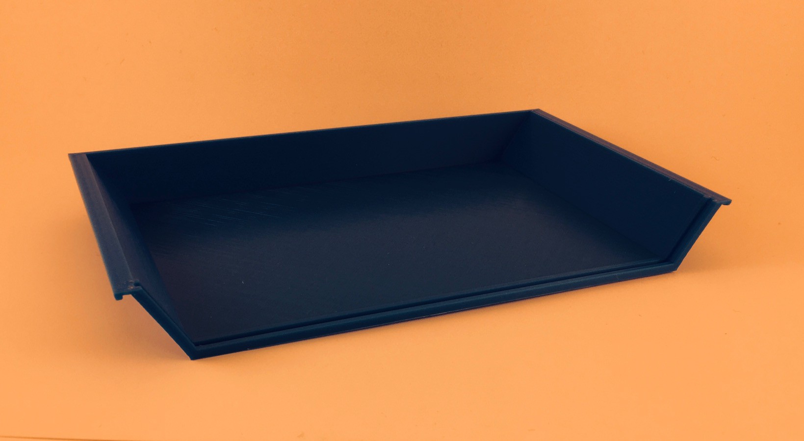
Nothing special about top piece. Notice the groove in both the top and bottom pieces used to hold the front panel in place.
![]()
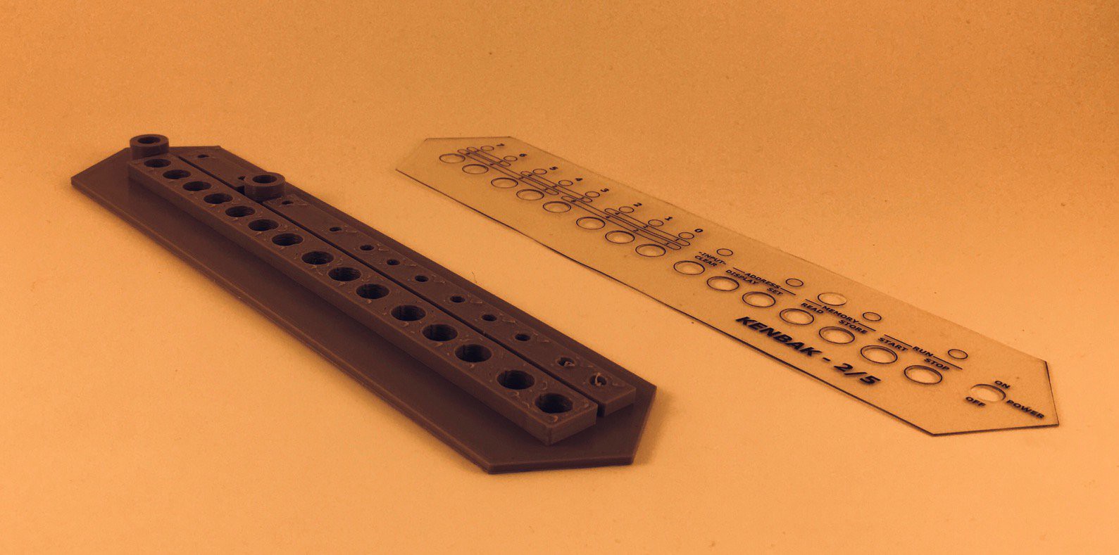
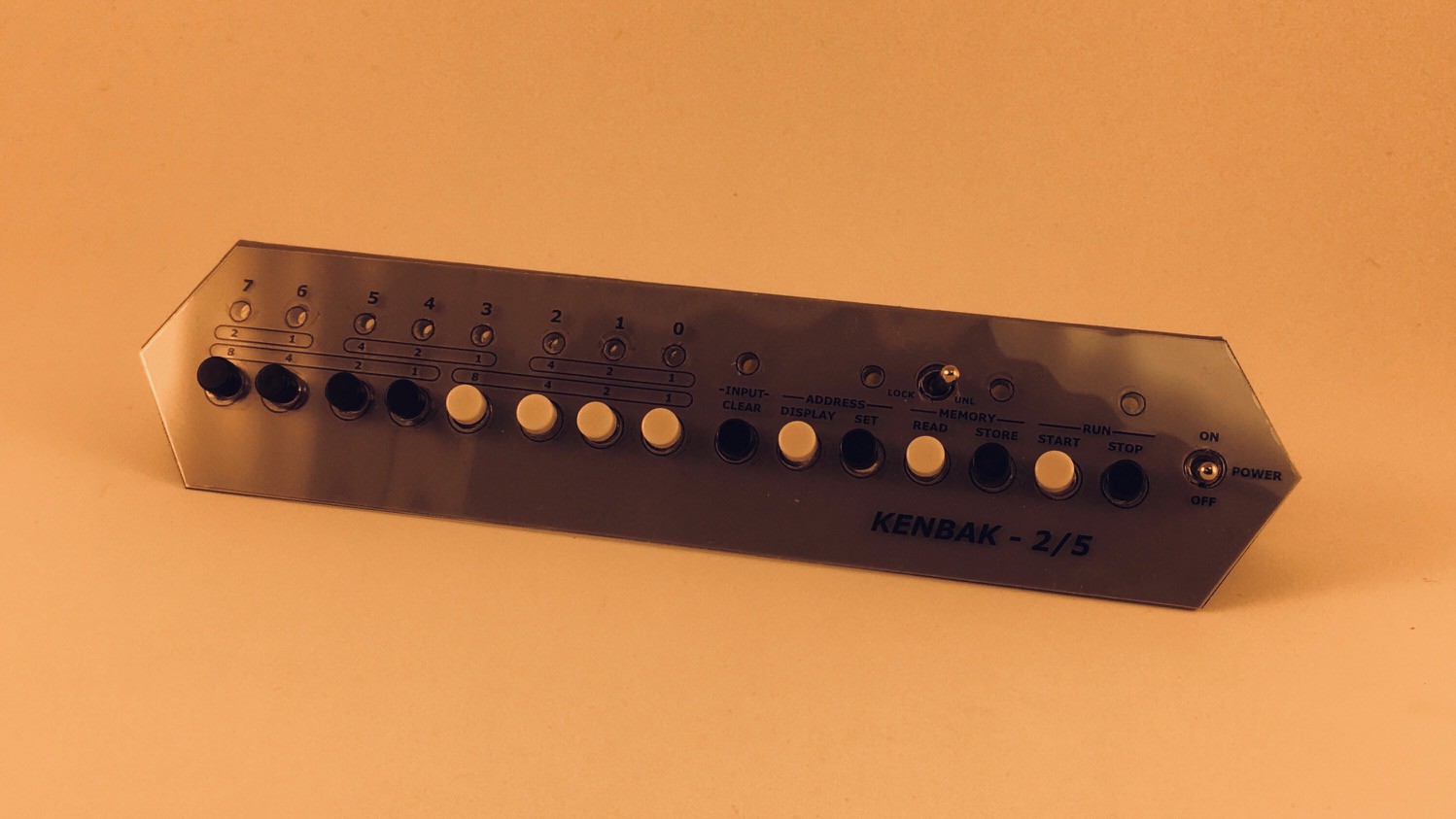
The front panel has holes to hold the buttons, switches, and lights. Because of the small size of the reproduction I was not able to just 3D print the labels directly on the panel as I have in the past with other projects. Instead I saved a DXF file with the panel outline and hole positions from my Fusion 360 model and brought that into Inkscape where I added the labels. I printed the resulting SVG file onto a clear overhead sheet which I laminated to protect the printing and add rigidity to the overlay. I cut the overlay out along the outline and punched the button and switch holes with a standard hand held 1/4" paper punch. The panel lights are recessed behind the overlay so do not require holes.
![]()
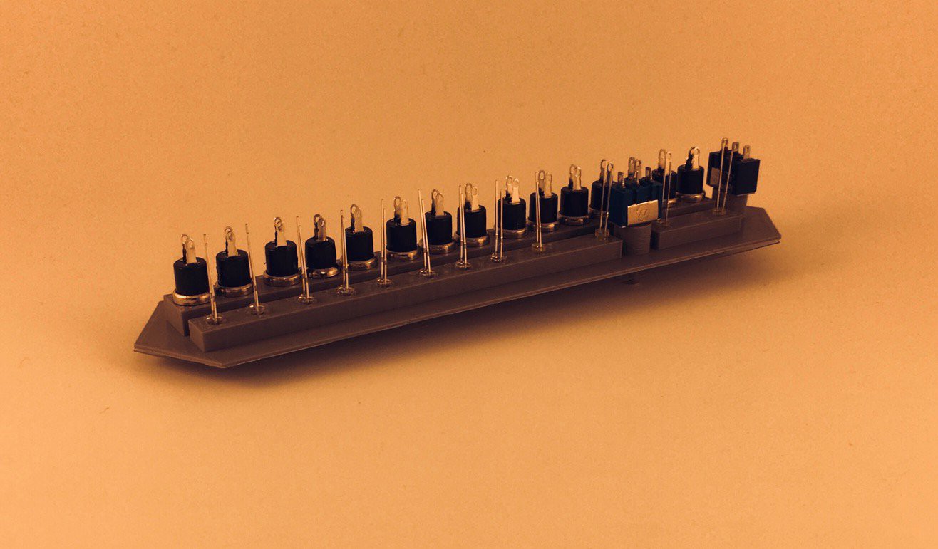
I could not use the nuts that came with the panel mount buttons and switches because they would not fit at this scale. Instead I sized the holes in the front panel so that the components could be screwed in from the back self threading as they did. The LEDs are just friction fit.
![]()
The overlay with the labels will just fit over the buttons and switches with a little finessing.
![]()
The front panel fits into the grooves cut into the top and bottom pieces.
![]()
Join the top and bottom pieces with the slotted side pieces.
![]()
And that's it for the console.
![]()
I'm waiting for the port extender hat. When it arrives I'll be wiring the KENBAK-2/5 up. In the mean time I'll be working on the software side.
2:5 Scale KENBAK-1 Personal Computer Reproduction
Make a working reproduction of the venerable KENBAK-1 with a fully integrated development environment including an Assembler and Debugger.
 Michael Gardi