Arya
Arya-
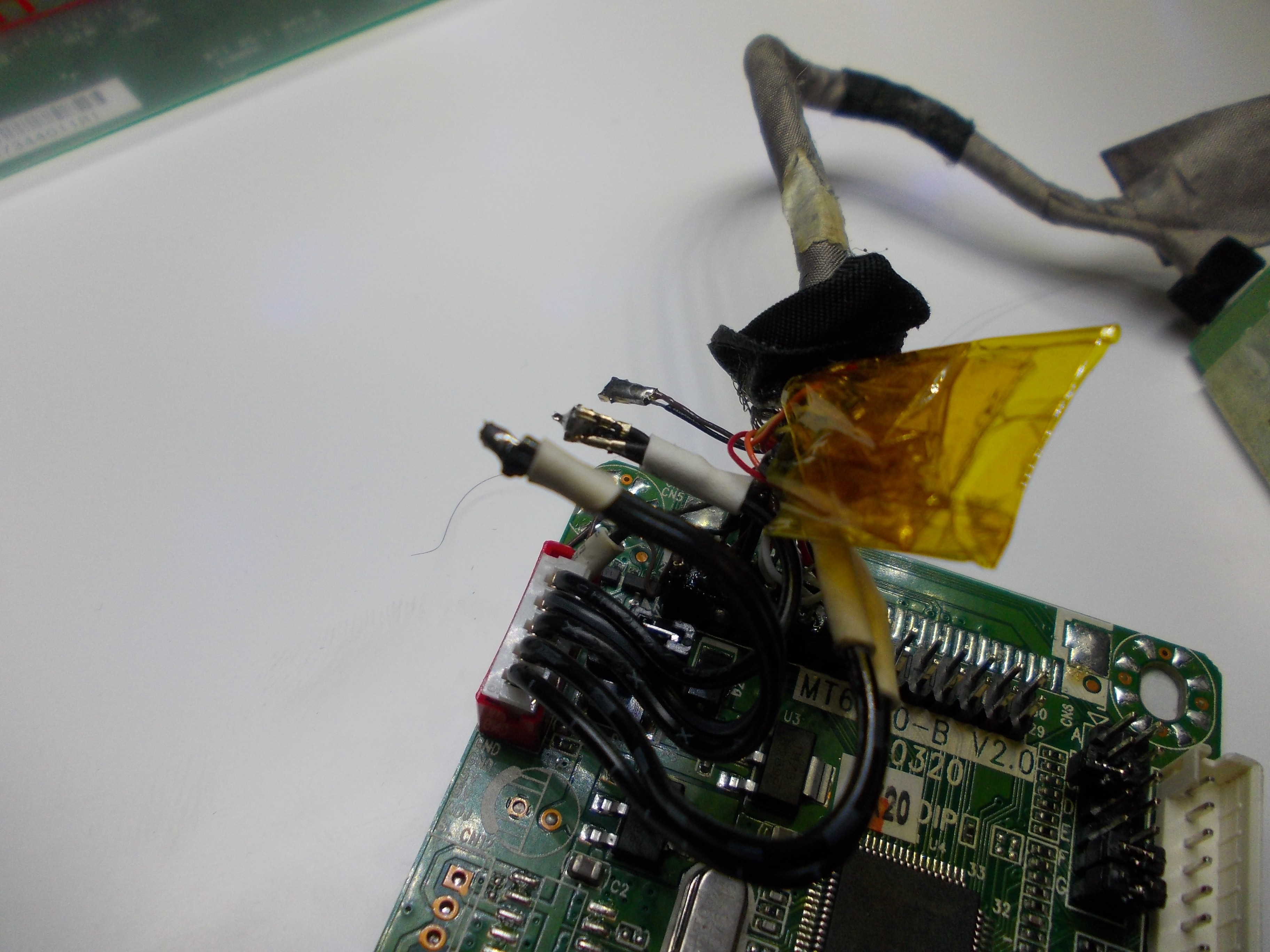
Programming PCB800862
07/12/2024 at 18:02 • 0 commentsBurning Firmware onto PCB800862
PCB800862 is an RTD2556 based controller board. Features include:
- USB C input
- HDMI input (mimi HDMI/HDMI C connector)
- Audio output
- USB hub
- PD charging
- Supports up to 1920x1200 supposedly, although I have not been able to get it work on my panel.
See the files section for the specs (in poorly written Chinese, don't blame Google translate). This log probably applies to other RTD based boards as well. But I haven't verified.
Programmer Hardware
I am using this ISP programmer from AliExpress. There are some DIY versions based on Raspberry Pi floating on the Internet. I haven't tried any. Leave a comment if any has worked for you.
The programmer communicates with the controller board using I2C over the VGA, HDMI, or DVI connector. I have only used the HDMI.
Programmer Software
I got the software from the vendor who sold me the programmer. It runs only on Windows. I was worried that it wouldn't run on Windows 11 but it seemed to work fine.
See the files section for the software bundle.
Firmware
I got the firmware pack from the vendor too. They made it sound like it works for PCB800860, PCB800862, and PCB800863. I only have a PCB800862 to verify.
See the files section for the firmware pack.
Notes
Verified working:
- 1920x1080 2-ch 6-bit
- 1366x768 1-ch 6-bit
Did not work:
- 1920x1200 2-ch 8-bit, at least not on CLAA260WU11
-
Common eDP laptop panel pinouts
08/13/2022 at 00:00 • 0 commentsThis is a page where you can find common laptop/desktop LCD eDP panel pinouts and see if your laptop screen's pinout matches any one of them (it likely does!).
All of these displays use the I-PEX connectors, as mentioned here.
Common pinouts:
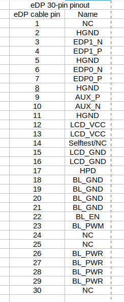
A: 30-pin connector (two eDP lanes)
![]()
[TODO: insert laptop panel connector photo]
This is the most popular kind of pinout, used by majority of displays - aka all the 1080p and 720p displays out there, save for a rare panel with on-cell touch. It's forwards compatible with 40-pin touch-enabled panels (omitting touch support) using a 40-pin to 30-pin eDP adapter.
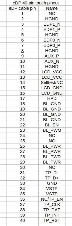
B: 40-pin connector (two eDP lanes + touchscreen)
---------- more ----------![]()
[TODO: insert laptop panel connector photo]
This pinout is used by panels with a built-in (on-cell) touchscreen layer, such as the B156XTK01. It's backwards compatible with 30-pin panels (losing touch support) using a 30-pin to 40-pin eDP adapter.
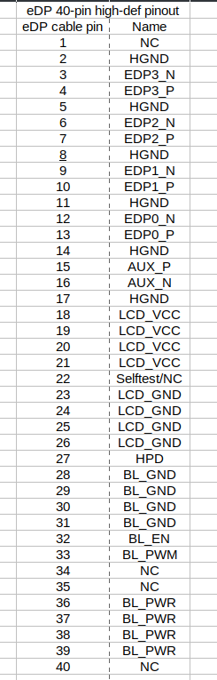
C: 40-pin connector (four eDP lanes)
![]()
[TODO: insert laptop panel connector photo]
This pinout is used for displays over 1080p/1200p resolution, i.e. 2k/4k displays, since they need extra lanes. However, this pinout doesn't have touch support.
-
[WIP] Connector types
03/23/2022 at 09:42 • 0 commentsLCD panels use different connectors, and for some projects, you might need to source the connectors, plugs or contact. Here, I'll gradually assemble information about part numbers, as I either find it or someone else shares it. If you cannot find it here, mind that often connector information is found in your LCD's datasheet, or a datasheet of an LCD with the same connector. If you find information that isn't present here, please leave it in the comment section below!
---------- more ----------
FI-X 30-pin connectors for CCFL LVDSThese tend to be JAE FI-X series connectors. Such connectors are found on cables like FIX-30P-D6 and FIX-30P-S6, typically used for CCFL-backlight LVDS LCDs. Contact housing (plug) is called FI-X30H (HL for the locking version), individual contacts can be found as FI-XC3A-1-15000 and mating parts can be found as FI-XB30SSLA-HF15, FI-XB30SSRLA-HF16, FI-X30SSLA-HF, FI-X30SSLA-HF-R2500 - there might be more, but they all should be described on the page linked right above. On Aliexpress, FI-X30SSLA-HF-R2500 has given particularly good results for sourcing SMD connectors themselves.
Thanks to @helge to sharing this!
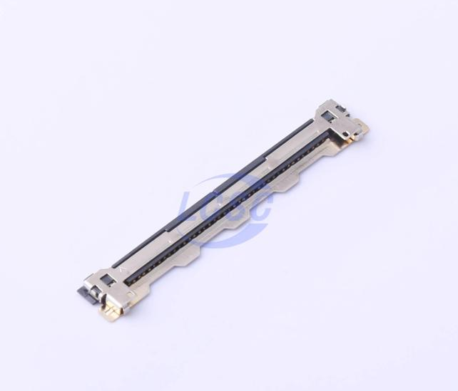
40-pin and 30-pin LVDS-LED and eDP connectors
![]()
The 40-pin version
These connectors tend to be used for both LVDS LED-enabled and eDP screens (30-pin for common ones, 40-pin for high-res or touch-enabled screens). The original part number seems to be I-PEX 20455-030 and I-PEX 20455-040, and the 30-pin and 40-pin SMD sockets are found on LCSC as JUSHUO ALC04-S30EIA-00 and ALC04-S40EIA-00 respectively. I searched for "LVDS" in the search bar to find these. Hopefully, that helps.
-
eDP controller boards
07/25/2021 at 12:45 • 0 commentsThis is a list of eDP display controller boards, with their parameters and some notes on each specific board. More boards will be added as I buy and test them.
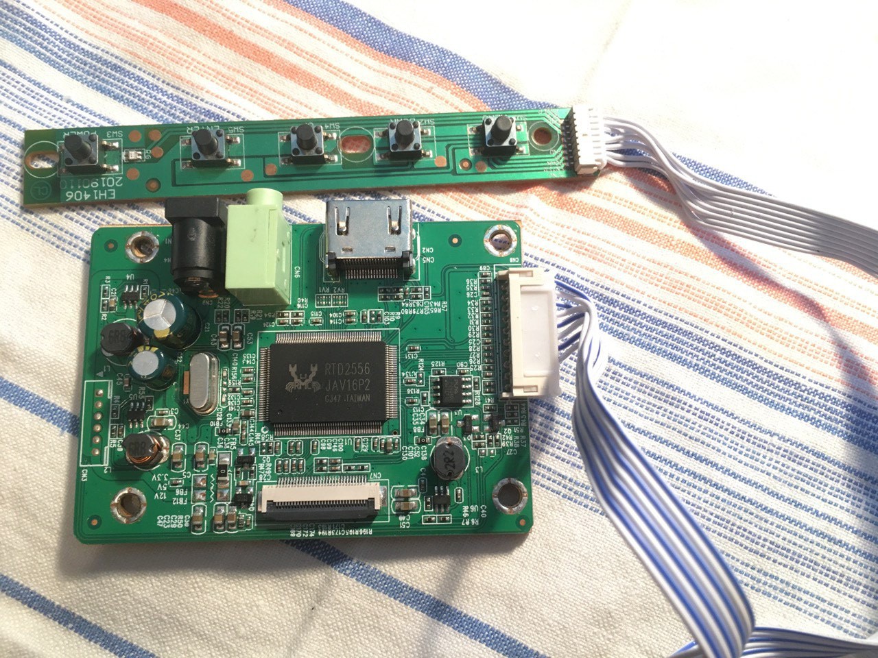
a. HDMI-only board with flashable resolutions
- Chip: RTD2556
- Power input: 12V, 5.5-2.1 barrel jack
- Audio: 3.5 output
- Resolution: depends on firmware
- eDP connector type: 30-pin
These boards are typically available cheaply ($12/piece) with 1080p firmware flashed in.
![]() ---------- more ----------
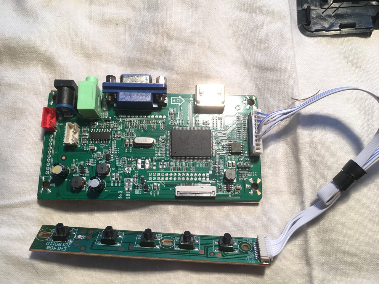
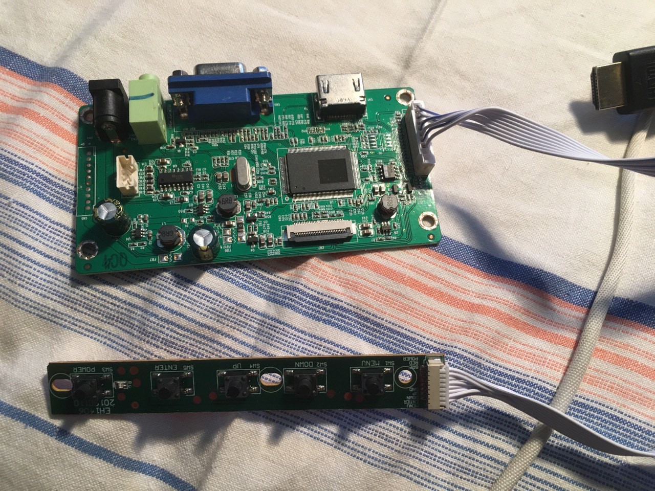
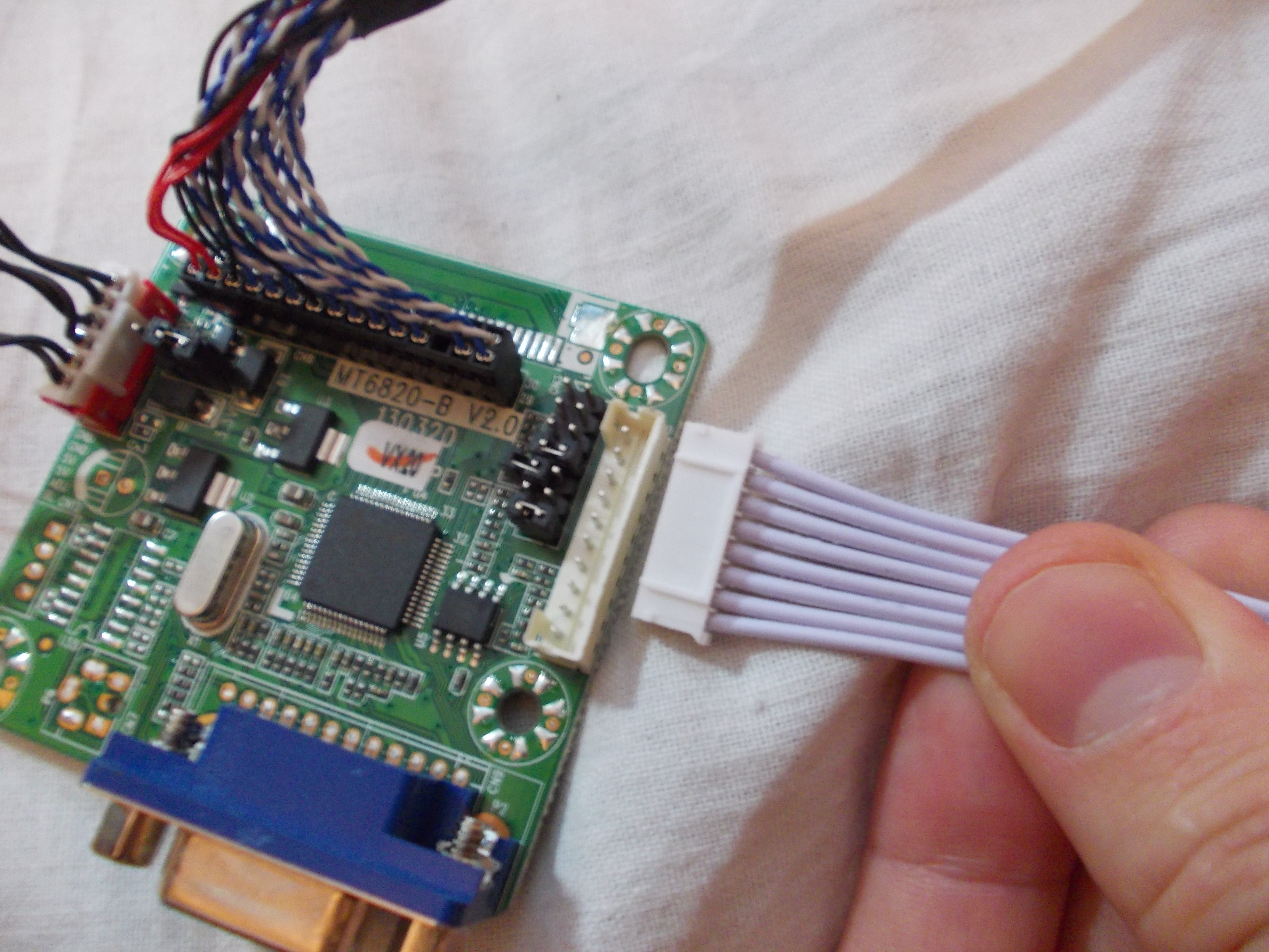
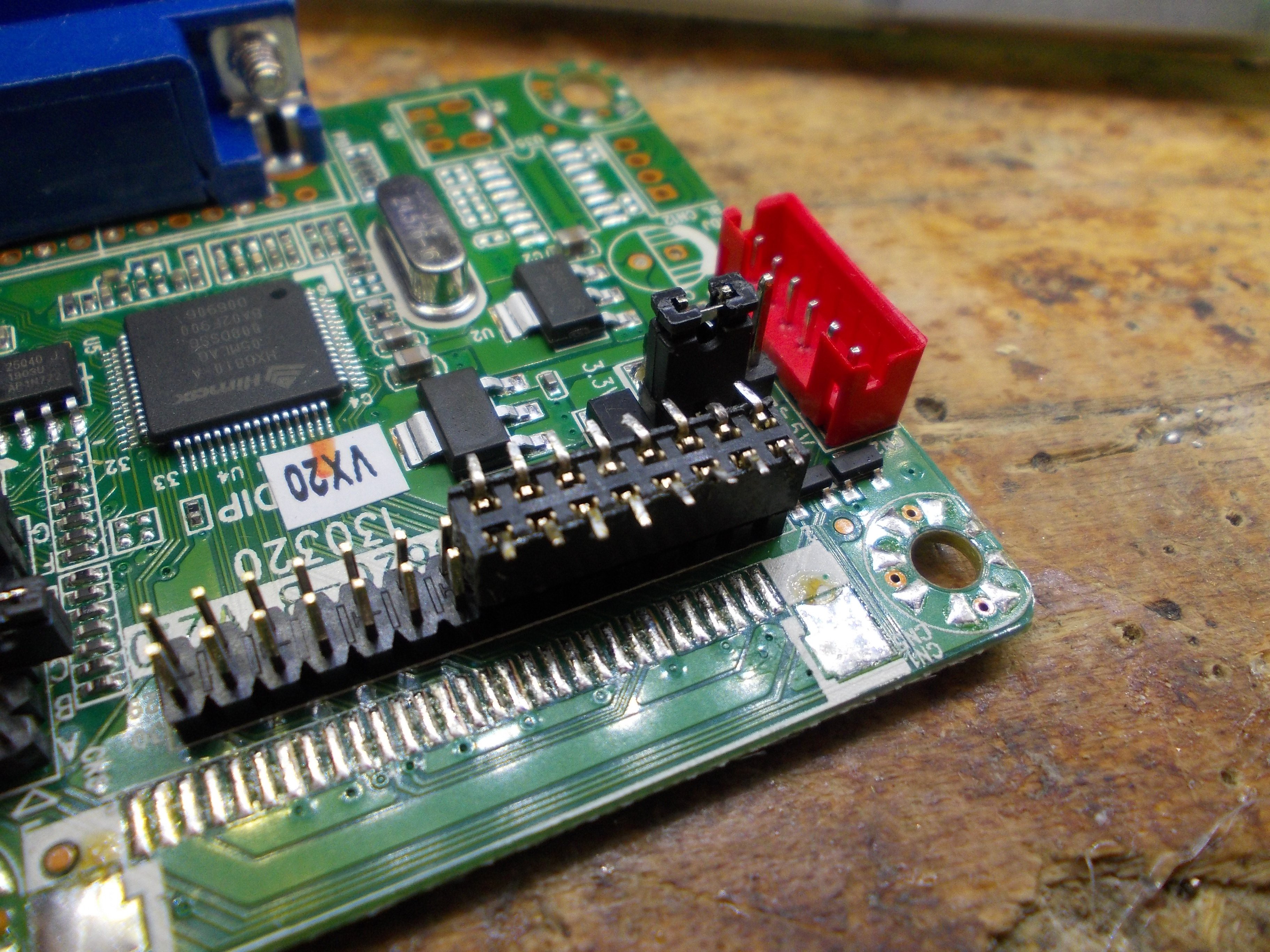
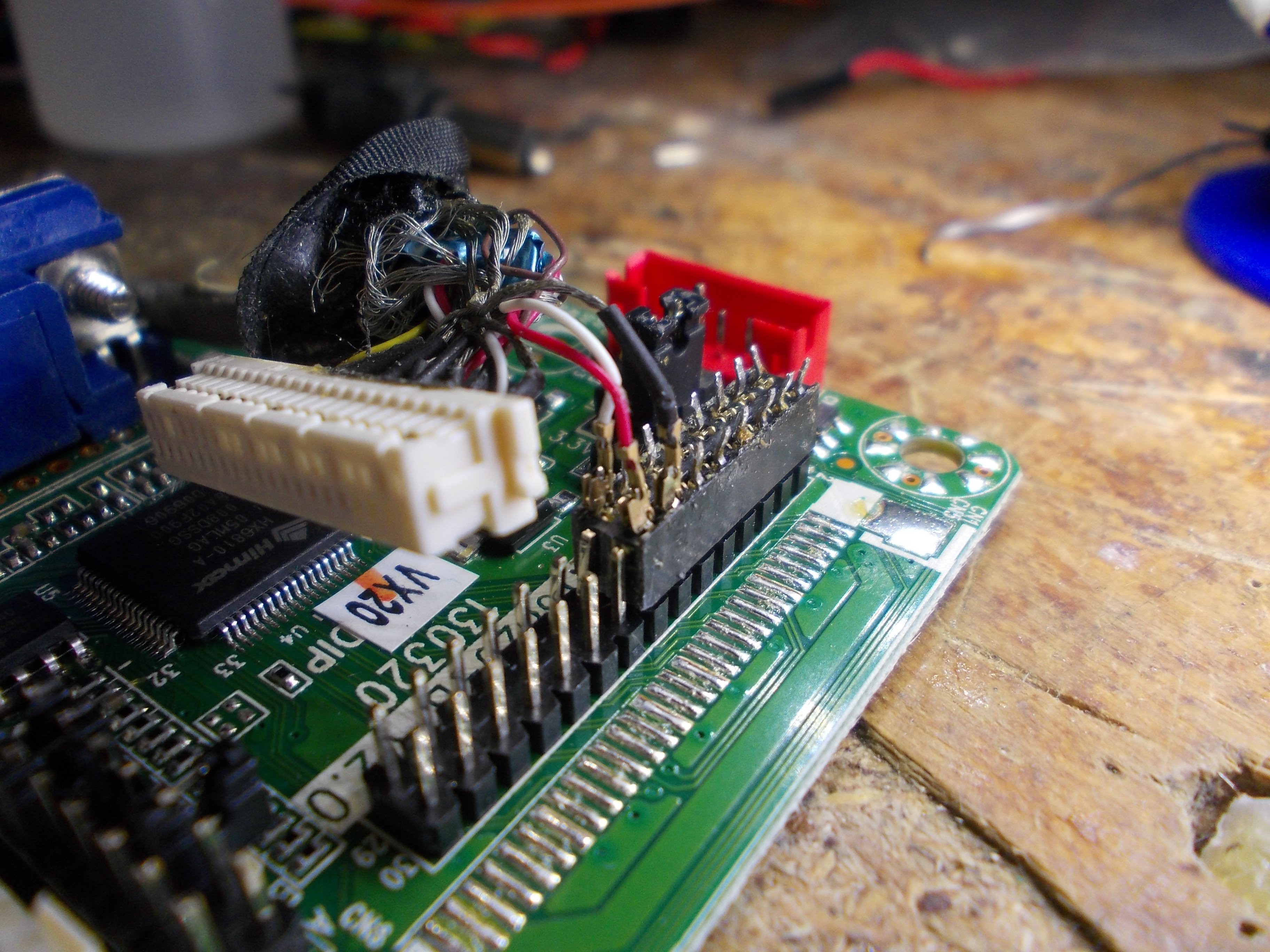
---------- more ----------b. HDMI+VGA board with flashable resolutions
- Chip: RTD2556
- Power input: 12V, 5.5-2.1 barrel jack
- Audio: 3.5 output + speaker output (onboard amplifier)
- Resolution: depends on firmware
- eDP connector type: 30-pin
There's different variations of this board floating around, some have additional connectors that can be soldered to if you'd like to embed the board in a project. You can switch between the VGA and the HDMI ports using the buttons.
![]()
![]()
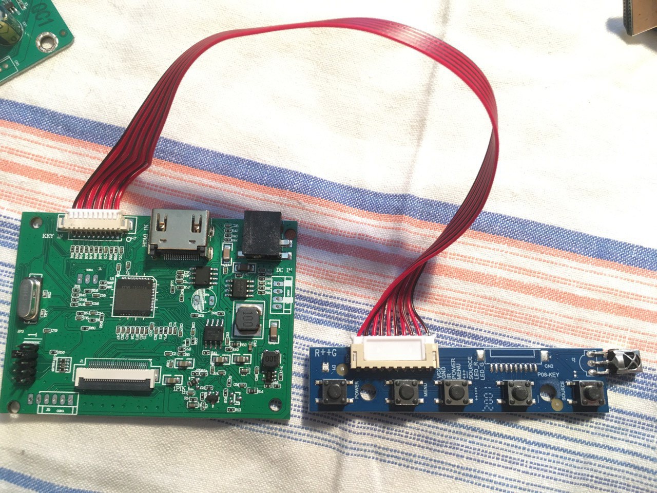
c. HDMI-only board with jumper-adjustable resolutions
- Chip: unknown
- Power input: 12V, 5.5-2.1 barrel jack
- Audio: none
- Resolutions: 1920x1200, 1920x1080, 1600x900, 1366x768, 1280x800
- eDP connector type: 30-pin
This board has an IR remote, for whatever reason - it doesn't seem to have any extra functions that the physical buttons won't give you.
![]()
-
[WIP] Demo - reusing an Asus X200CA touchscreen
07/25/2021 at 08:46 • 1 comment![]()
I bought two of these touchscreens on eBay, complete with controller boards and frames. I had one 11.6" display available to me already, and another one wouldn't be too hard to source in the future if I decided to. But first, gotta successfully reuse one of these to make sure my idea works.
[ TODO: pic ]
This one is certainly a USB device - most of modern laptop touchscreens are - so most of the laptop webcam reuse tips will apply. I need to find VCC, D+, D- and GND. There's 4 pins on the connector, so I don't have to worry about pins like EN and RST being present - they are on some touchscreens, but not this one.
The connector receptacle isn't something that I have a plug for when looking through my collection of random wire ends. This means I have to solder to the touchscreen board, sadly.
---------- more ----------I'm using 4 individually insulated copper wires to solder to this board. To remove the insulation, I need to hold the wire end inside a blob of melted solder on the tip of my soldering iron so that the insulation burns away a bit, my soldering iron is set for 330C for that.
Some touchscreens actually want 5V VCC, others need 3.3V. How do I determine that? I usually just power them from 3.3V and then, if they fail to work, do research to see if perhaps they'd need 5V. This time, I had a connection problem and decided to double-check whether the touchscreen would work from 3.3V, so let's go through my process of researching whether a touchscreen is 3.3V or 5V.
Determining voltage
There's three ways to know a touchscreen's voltage with certainty:
- Markings on the touchscreen board itself (if the touchscreen PCB says "5V", it likely takes 5V)
- Measuring it on an assembled and connected laptop (not an option in this case)
- Schematics and boardviews
I didn't have 1 and 2, so I had to resort to 3. Asus X200CA doesn't have schematics available but there's boardview files. With OpenBoardView and the FZ key, I was able to open the boardview file and browse it. Now, where do I find the touchscreen connector?
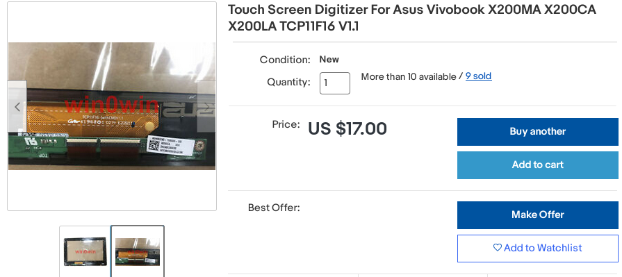
Sometimes the touchscreen cable is a separate cable, and sometimes it's the same cable that also carries the display signals, and I need to know this to know which connector to look for touchscreen signals on. I looked up "x200ca cable" on eBay and found this:
![]()
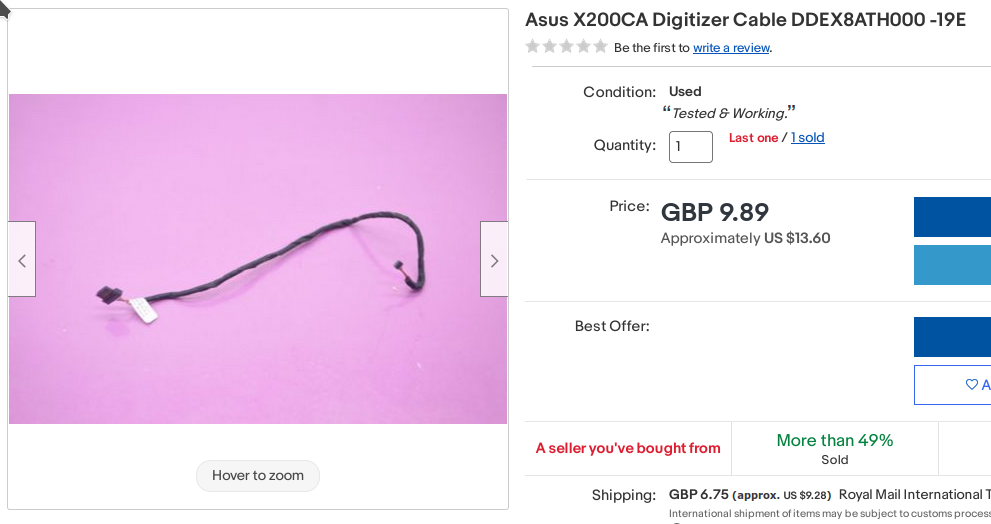
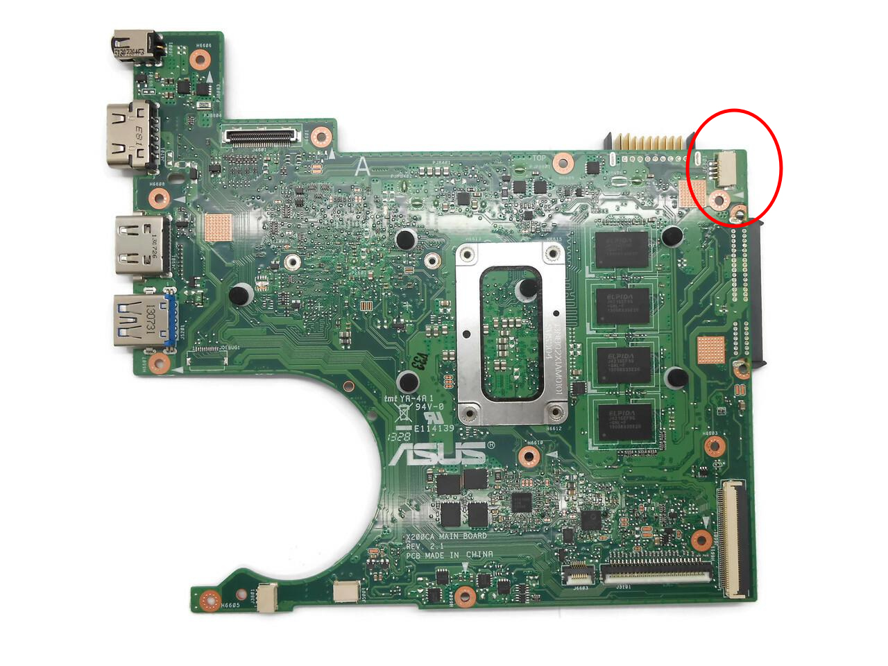
Looks like exactly the cable we need, one connector (right) is the kind of connector that plugs into our touchscreen controller board, and another one (left) is a Molex connector often used in laptops. So, the touchscreen has a separate connector. I could look up an "Asus X200CA teardown" video on YouTube and see exactly where that wire goes, but I saved a bit of time by googling "X200CA motherboard" and looking at images:
![]()
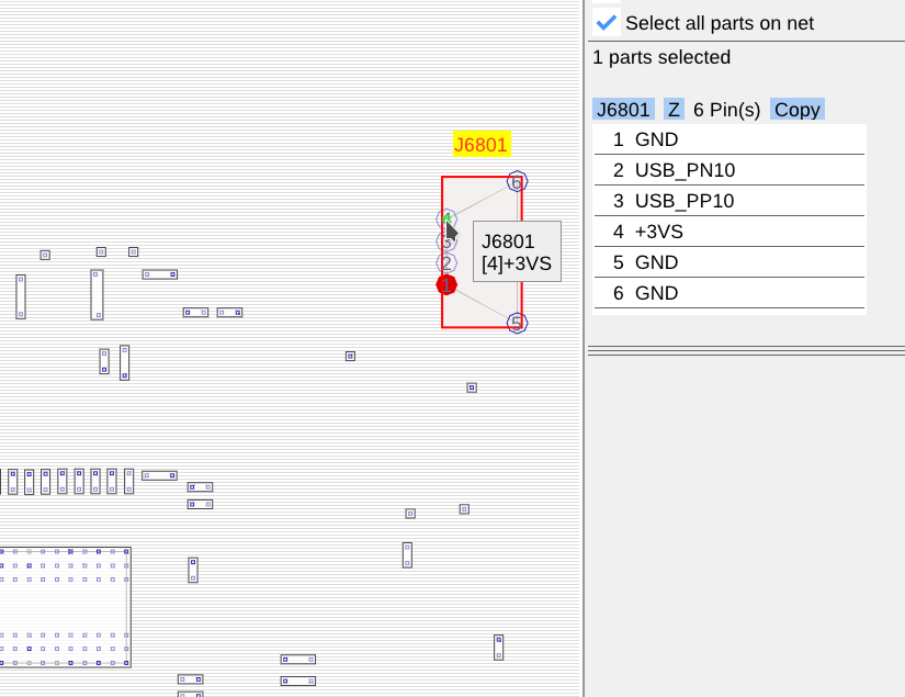
This connector instantly looked like the thing I needed. I located it on the boardview and, indeed, it has GND, USB signals and 3.3V:
![]()
So, it's decided, the touchscreen wants 3.3V, and it's good to know that for sure - now I won't think "oh, maybe it needs 5V after all" and end up accidentally destroying it.
Determining pinout
The "determining voltage" part isn't necessary if you're not having doubts about the right voltage, that'd happen if the touchscreen fails to work at 3.3V, for instance. Otherwise, I'd say, you are pretty safe just powering it from 3.3V.
The pinout, however, has to be determined. I usually take a multimeter, find GND, then VCC, then USB D+ and D- - as the latter are hard to tell apart, I try them in one polarity and swap them if they don't work.
[ TODO: pic ]
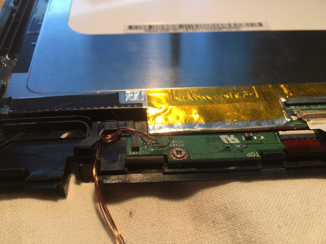
This controller board is already connected to the touchscreen glass and screwed to the touchscreen frame. I see no use in disconnecting and unscrewing it, there's more than enough exposed pins on the part of the board accessible to us.
[ TODO: pic ]
GND is likely to be at the screw hole - checking with a multimeter, there's indeed connectivity between one of the pins on the 4-pin connector and the metal around the screw hole. It also is connected to all of the capacitors on the board, so that cements it, we found GND. I won't solder a wire to the screw hole itself, but instead to one of the other GND points on the board.
[ TODO: pic ]
These two traces going to two resistors are an obvious differential pair, so there's our USB. That leaves the one remaining pin as VCC.
[ TODO: pic ]
VCC is very prominent on this board, it's a thick trace going somewhere to the right from the connector. Even the connector's mechanical pins are connected to VCC and not to GND, as usual - not that it matters this time.
![]()
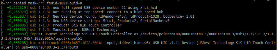
Now, I just connect wires from my small microUSB+3.3V breakout board to the touchscreen, and, after swapping D+ and D- wires once (at the breakout, not at the connector), it works:
![]()
Of course, it's out-of-the-box on Linux, with Windows, your mileage may vary. Sometimes Windows wants drivers, even if it's a popular touchscreen - usually isn't needed with Linux, thanks to all of the in-kernel drivers.
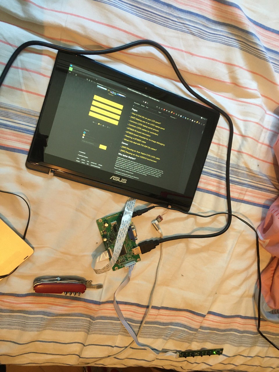
I touch the touchscreen (from its front size) and the mouse pointer of my laptop moves! Ain't that nice. After fastening the wires a bit, I decide that I've successfully reused this touchscreen. Now it just needs a display fitted to it:
![]()
Perfect.
-
Project plans
06/14/2021 at 11:57 • 0 commentsI'm building this project as a knowledge database, complemented with a 0% to 100% guide for laptop display reuse. I want to take everything I know about this topic, lay it out somewhere, add new research where needed, and provide assistance to people in our project's chatroom. I'm also using this project to help me introspect and take notes on my own ability to follow the goals I set for myself - what helps me put ongoing effort into projects, when do I pause it, and once I do, how and when do I resume it?
Over the next X months, I'll be adding information on topics I've already achieved things in during the past years:
- CCFL inverter reuse (having reused multiple different inverters)
- eDP screen reuse (in fact, I'm working on the LVDS articles first because it's more popular, but most of the screens I work with are eDP)
- Laptop display assembly reuse (having reverse-engineered a display assembly for Lenovo Flex 2-14)
- Touchscreen reuse (having built myself a touchscreen-equipped external monitor)
- Triaging and quickly sorting through a large pile of laptop screens (as I have about 50 different ones from my laptop repair days)
- Reusing screens with broken backlights and/or cracked LCD panels (for instance, I use the acrylic panels from laptop LCD backlights a lot in my projects).
- Hacking the available controllers to achieve lower power consumption and better "sleep mode" abilities.
I'd also like to work on the topics that I haven't yet worked on or that are more technical, like LVDS and eDP internals, term disambiguation, TTL to LVDS conversion nuances, different controllers' power requirements, managing high-speed LVDS/eDP interface and CCFL noise in your projects, and how to securely mount a laptop display so that its brittle parts are protected from the harsh reality of the outside world.
Along the way, I will be assembling lists of information and projects, for instance, a list of all the commonly available LVDS and eDP controllers, their nuances and parameters, links to interesting projects where the "laptop LCD reuse" aspect really shines, others' blog posts with insights into i.e. the technical side of LVDS/eDP or other things I can't cover or won't have time to cover myself.
One of my endgoals, apart from completing this knowledge database, is filming a video, about 10-20 minutes long: "How to reuse a laptop display - from start to finish". While I'll be working on guide articles, such as this WIP one, I can imagine a video reaching as many people as possible. This would be a decent way to help people understand the whole reuse thing, especially those people who are better at following videos than they are at following text guides.
---------- more ----------I will also be buying controllers and parts from eBay and other places for research purposes.
For instance, there's a way to reflash the popular "universal" LVDS and eDP controllers into different resolutions and modes. There's cheap 1080p-configured controllers ($13/pcs) available online, however, controllers for the more abundant and cheap 768p panels use the same hardware, yet are listed at $20 and higher. I want to eventually buy one-two of the 768p controllers and dump the 768p firmware off them, so that people can buy cheaper 1080p controllers and reflash them into 768p controllers, saving quite a bit of money.
There's also $25 programmer boards, with some kind of application-specific USB dongle, that allow you to update M.NT68676 boards, flashing firmwares with different resolution. My research shows that even the MT6820 board might be reflashable this way, which would make my MT6820 firmware experiments a lot more useful all of a sudden!
![]()
I'm certain the firmware update protocol is easy to replicate with a Raspberry Pi, however, I don't yet have the dongle so that I could sniff the protocol. However, one of these months, I'll invest into buying one of these boards, for sure =)
Every month, I'm buying one-two different controllers so that I can check them out, see if I can recommend them, and measure their power requirements. I will also be looking into easily-reusable and cheap display assemblies so that people can build portable touchscreen monitors on a budget and with a low entry level.
As someone who develops and orders PCBs on the regular, I will be inevitably developing and selling laptop-screen-reuse-oriented PCBs. For instance, it makes sense that one should be able to easily reuse eDP laptop LCDs by connecting them to a DisplayPort-equipped PC, as the interfaces are electrically compatible - resulting in a screen that's low-power and low-cost. However, this would require a small adapter board to be designed and made, and funnily enough, there isn't one on eBay or Tindie yet, so I will be working on designing one and attempting to produce them as cheaply as possible so that people can reuse their eDP displays on a budget.
After this project is reasonably completed, I might look into duplicating the materials to some sort of wiki and setting it up so that it can be community-edited and improved. For now, the HaD project format fits it reasonably well =)
Interested in working with me on some of these goals, or complementing the project in some way? Join me, there's a button somewhere above on the main project page =)
-
MT6820 board checklist for no-image debugging
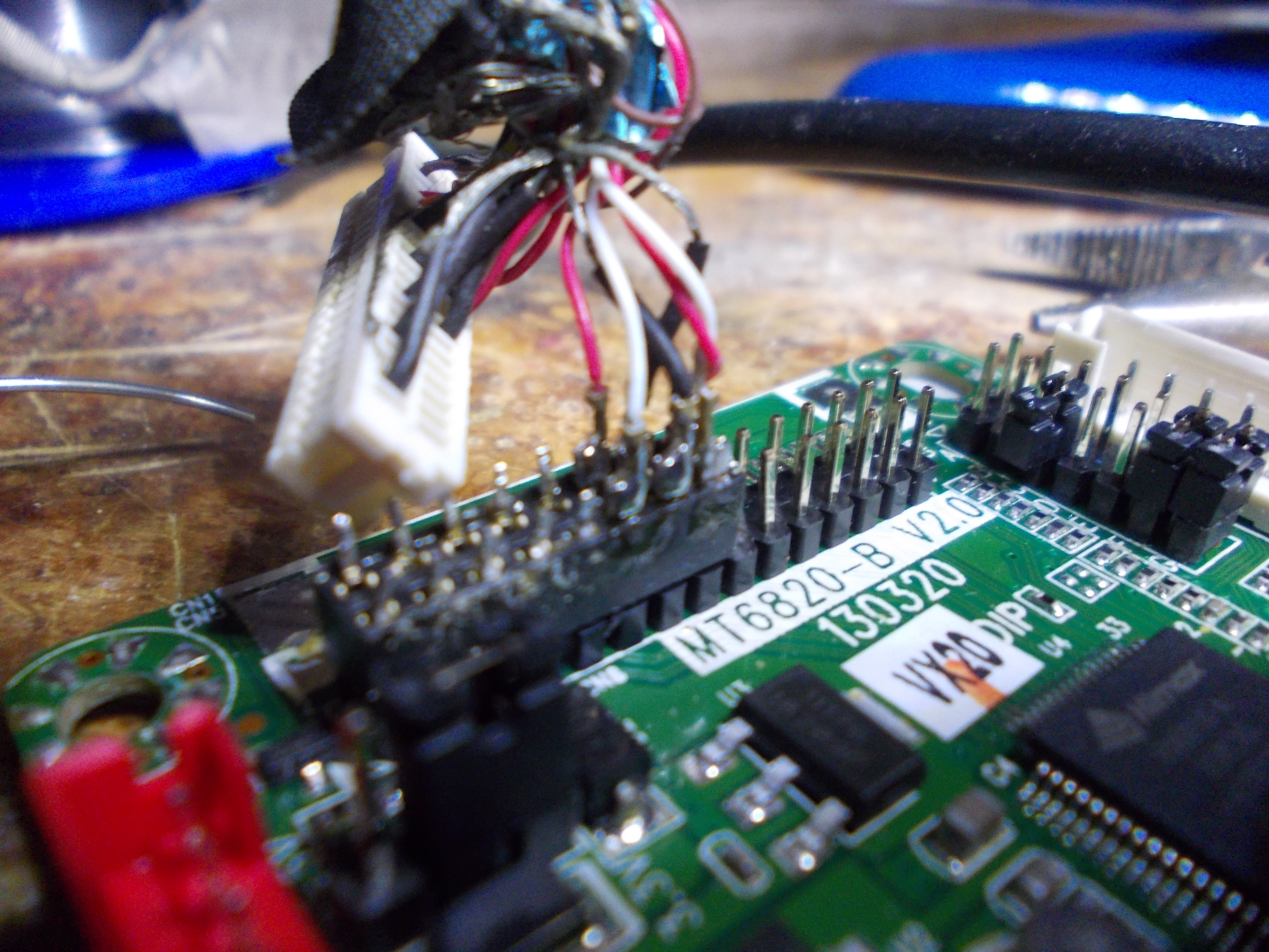
06/14/2021 at 11:57 • 0 commentsWhen it comes to reusing old laptop screens on a budget, MT6820 (also known as MT561) is a great board - for just $5, you get a VGA-capable board, a rewire-able cable and a button board. Here's more info on the MT6820 board, if you're curious.
Let's assume you got one, followed the info available here (or somewhere else) to make it work, and it... doesn't. What do?
Important note - this mainly talks about "no image"/"garbled image" scenarios, I'm not talking about "no backlight" scenarios, since backlight is usually taken care of by an inverter, an entity that has to be debugged separately.
1. Check that the panel voltage is set up correctly (likely, to 3.3V)
![]()
This kills the
crabscreen. If you've powered up your setup with the wrong voltage setting, the panel might be broken already. However, if you're sure your screen is 5V-powered, then it will require 5V to work and likely will not work with 3.3V. Having said that, overwhelming majority of laptop screens are 3.3V-powered.2. Is the keypad board plugged in correctly?
---------- more ----------The keypad board cable is two positions shorter than the connector on the MT6820 board. Here's how you should be plugging it in:
![]()
3. Is the LVDS connector rotated the right way?
The LVDS connector on the MT6820 board is a 2mm 2-row header. It's very possible you might plug it in the wrong way around. Look at the bottom of the board, the connector's pinout is listed there - VCC pins should match the red wires when you have the cable plugged in.4. Is the cable pinout correct?
First of all, the stock MT6820 cable doesn't work with laptop displays unless the store listing where you got it from explicitly states so. Here's how you rewire the cable you got if your panel uses the same connector but a different pinout. Alternatively, here are the cables you can buy, one of them is likely going to be suitable for your panel.Even if you got the correct cable, it doesn't hurt to check. Go find information on your laptop panel, and if you find a datasheet (likely), check which pinout it uses and whether the cable you got matches the cable that goes with that pinout (there will be a "Suitable cable" link right under the pinout description). If you can't find a datasheet, come to our chatroom and let's see how we can help you.
5. Are you connecting 5V to the board with the correct polarity?
The MT6820 board needs 5V power. Sadly, the MT6820 board doesn't have a dedicated power input connector, you need to either solder to 5V and GND pads somewhere on the board to power it, or use the JST-6 connector that's meant for the inverter. If you accidentally apply reverse voltage to the board, you might have a bit of trouble - I haven't had any of my boards die from that, but it will most certainly not work.6. Are you setting the resolution+mode jumpers correctly?
On your specific board, jumper settings might be a bit different from the ones available online, in the store listing description, or on my MT6820 description page. I highly suggest you un-peel that dumb sticker on your board that covers the silkscreened pinout table, and see whether the jumpers you've set match the resolution and the LVDS mode that you'd like to see. Also check whether you haven't confused the jumper row orientation - make sure that A in the table matches the A jumper and you haven't accidentally set them in an opposite direction, that's happened to me before.7. Is your PC (or other source) sending an image of the right resolution to the screen?
The MT6820 board can't do a whole lot of scaling on its own, from what I understand. If you send a 1024x768 image to the board with a 1280x800 screen, it might or might not work, so you better check that the controller (and therefore the screen) receives the data it actually can process.8. Are you using a dual-link LVDS cable with a single-link LVDS panel?
This is a weird one. I'm yet to write a proper worklog about this problem - but, basically, none of my 1280x800 (single LVDS link) panels work with a dual-link cable, specifically, FIX-30P-S6. I've recently investigated this a bit more, and it's basically a guarantee for 1280x800 panels. If you're using a dual-link cable, you will want to separate and temporarily unplug part of the connector on the MT6820 board side. [TODO: add a picture of how the cable should be separated.]I will be adding more checklist entries here as I find them, of course.
-
[WIP] Demo - reusing an Acer Aspire 5100 LVDS cable
06/14/2021 at 09:01 • 2 comments![]()
Laptop displays in their natural habitat use different cables than the controller boards do. These cables are, of course, not designed to work with a MT6820 or a similar board, the cable usually has a proprietary connector of some kind on its end that needs to be snipped off and replaced with a 2mm pin socket that a MT6820 board could accept, or connected to a small adapter board and an appropriate receptacle. That sounds like quite a bit of work, but actually, these cables are quite nice and often worth reusing.
- These cables work with the original display assembly - they fit nicely through the holes in the hinges, so if you're rebuilding a laptop with a new motherboard (i.e. building a Pi-based laptop inside another laptop's shell), reusing the original cable is a decent idea if the controller-suitable cable is too bulky.
- These cables are often well-shielded and won't radiate or receive as much noise, which is good if you plan to use them near sensitive circuitry of some kind.
- In case of CCFL screens, these cables also carry the inverter connections and plug into the original inverter used, which means you don't need to solder wires to the inverter and can use the original connector.
- Sometimes, they carry USB signals on a separate pair of wires, that USB is typically used for a webcam or a touchscreen, and you can reuse these wires as you see fit
- These cables are flat, which is a bonus for sleek designs.
The main problem, of course, is figuring out which wires on the proprietary end of the cable correspond to which connections. How do you do that?
---------- more ----------There's two ways to figure out how to adapt a laptop's cable:
- Sit down for a couple dozen minutes and use the multimeter to map out the cable connections
- Find a schematic for the laptop the cable was used for and use that to see what connects where and why
Neither of these options are bad, the first option is guaranteed to work as long as you don't confuse anything, however, the second option is quicker and more foolproof. It requires two things - that you know which laptop the cable is from, and that the schematic is available. If you don't have both of those, you will have to fall back to the multimeter method.
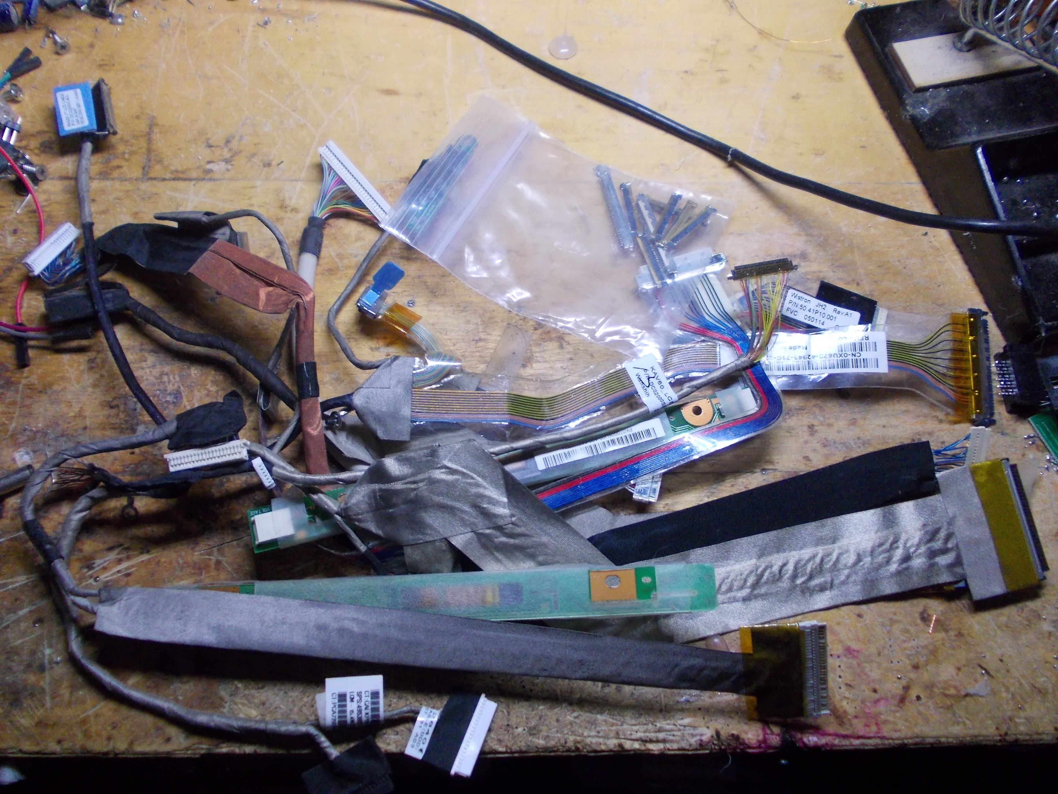
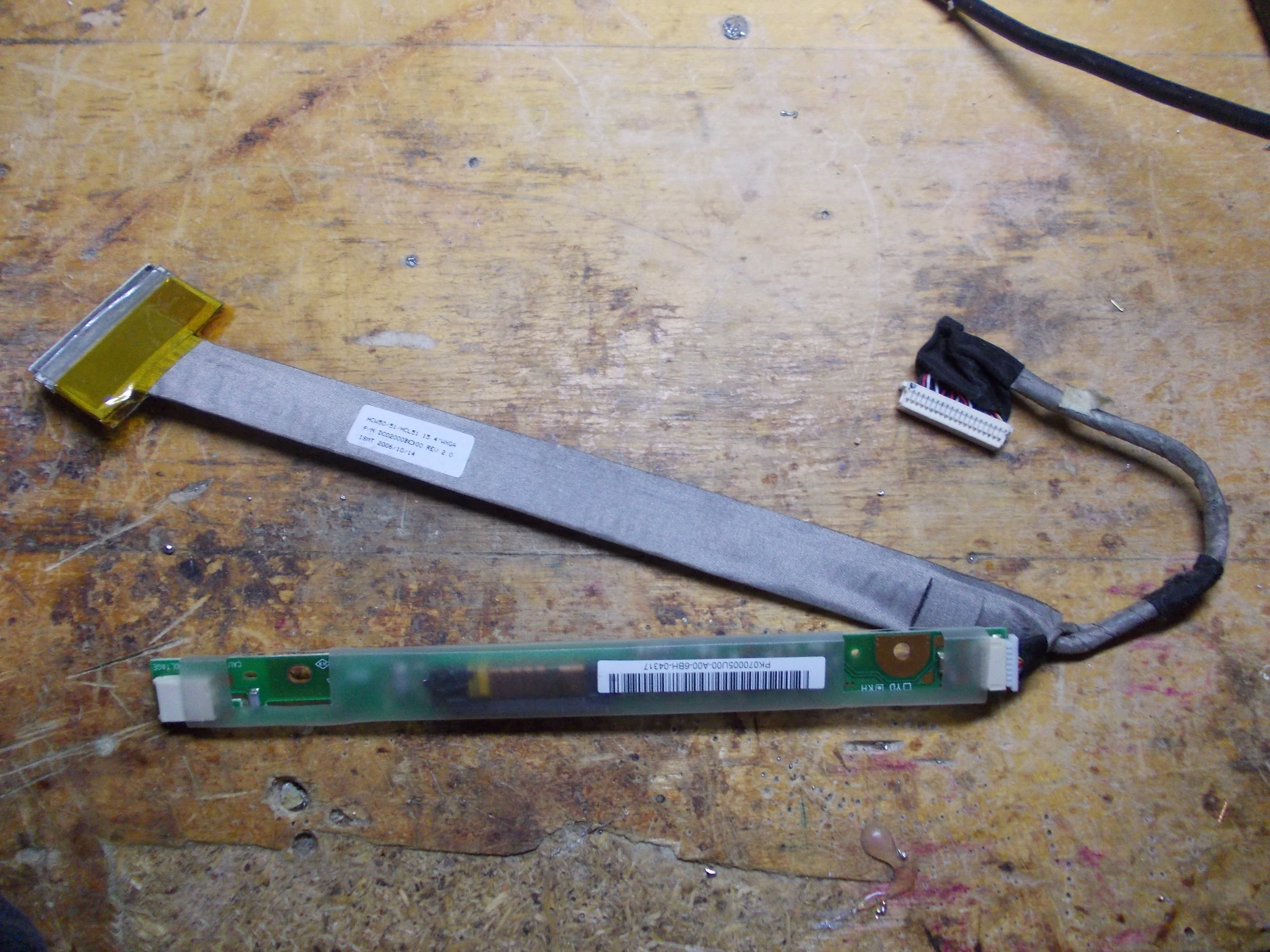
Let's look at one of the cables I'd like to reuse:
![]()
It's long enough (longer than the cable I got bundled together with a MT561 board), it has inverter connections, which is nice because I don't need to pull a separate cable, and it's also flat, which means I'll be able to make quite a sleek setup!
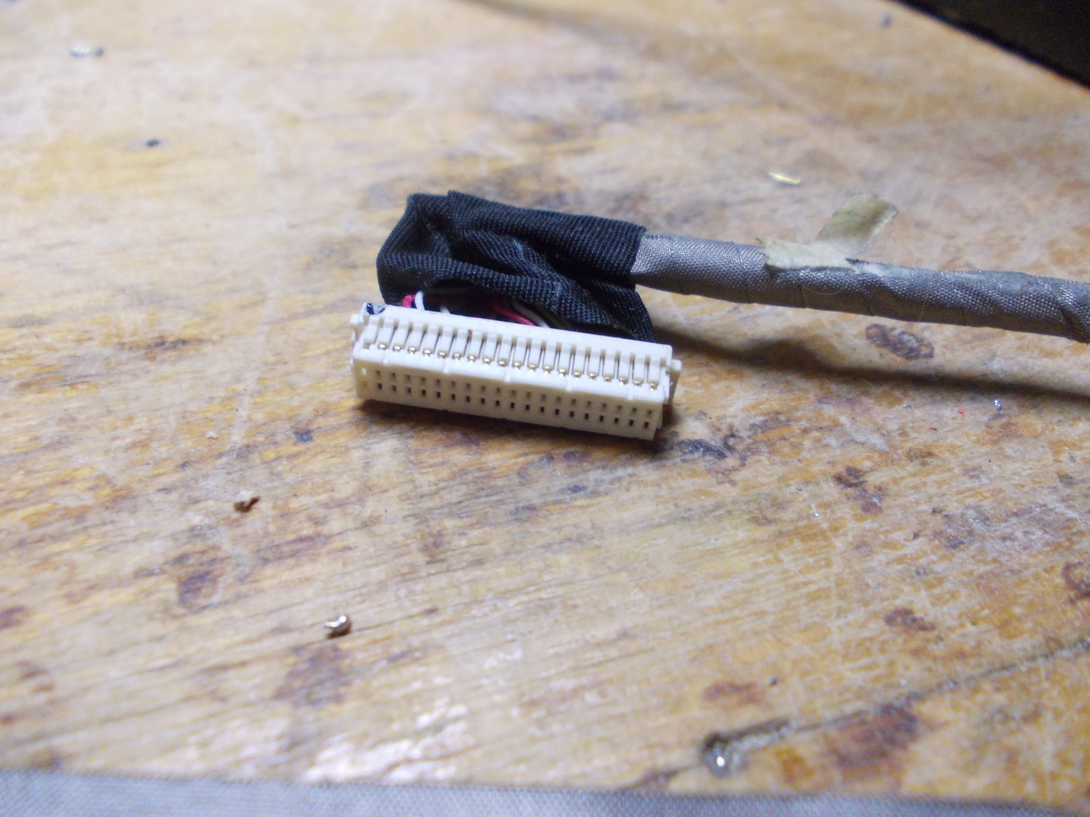
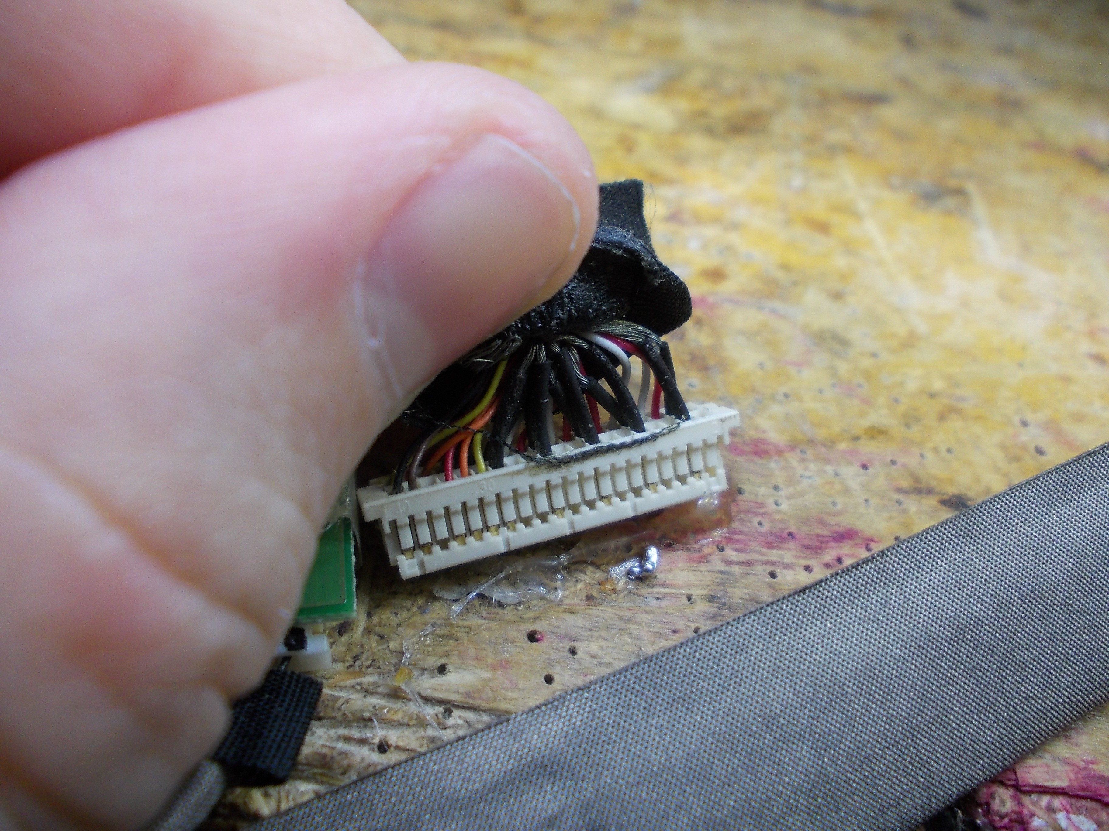
However, I don't know anything about this connector:
![]()
It's a connector I can get a receptacle for, these are some kind of JST connectors, but I'd need to design and order a board, that'd take a lot of time and not worth it for an one-off build. So, I will just get the wires out of this shell and solder them to a 2mm connector.
![]()
If I unpeel a bit of the tape, I can see that there's groups of wires that look like LVDS pairs - if I were to RE this connector without a schematic, it'd be a good start! The shield wires are, certainly, GND, there's more than enough of them, too.
[TODO: elaborate more about this cable's LVDS pinout and configuration]
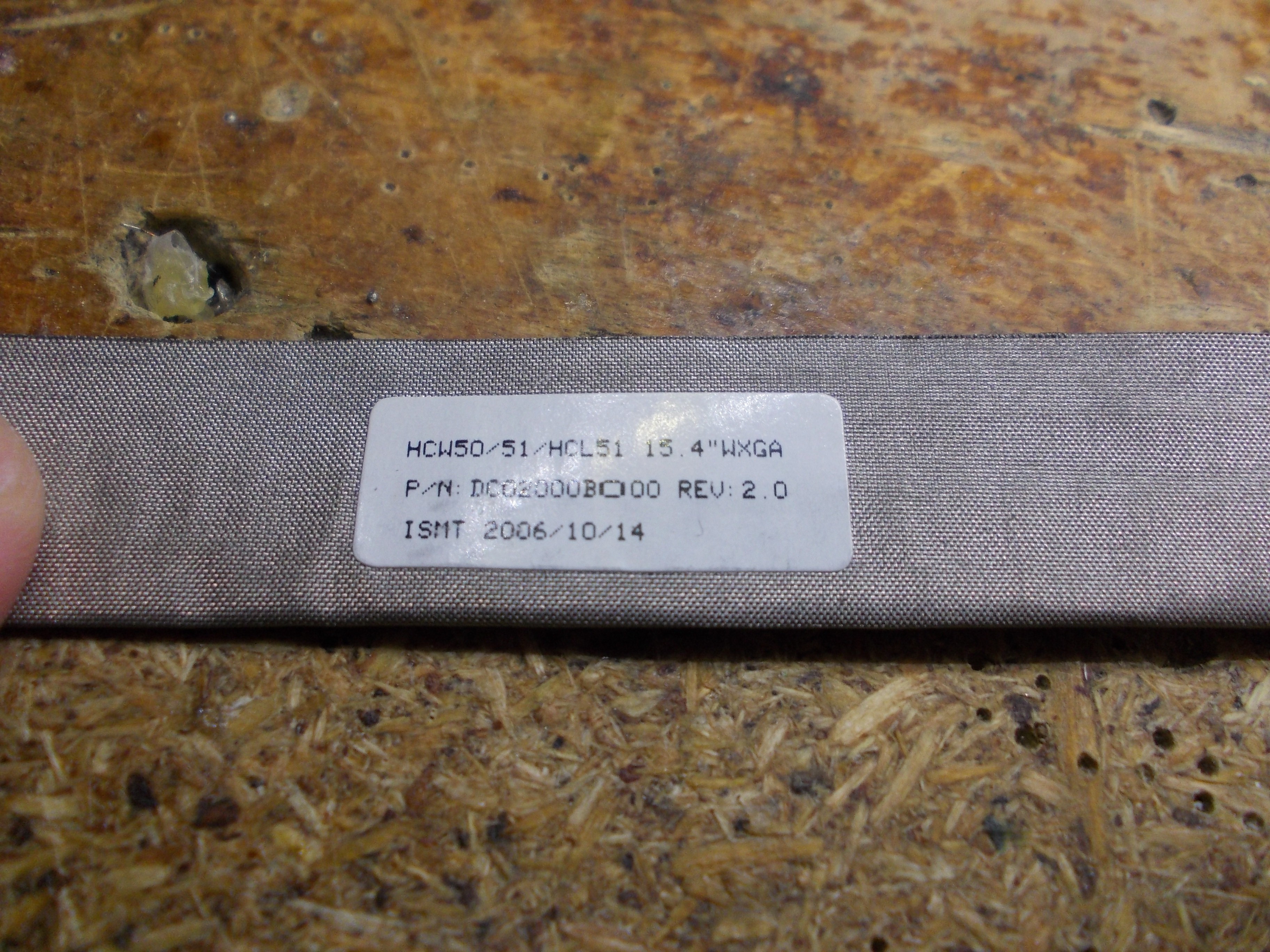
There's one more thing - a marking on the cable:
![]()
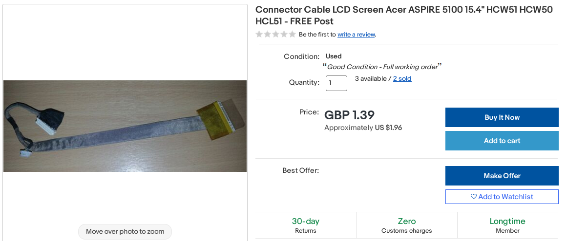
If we punch that into eBay, we get this:
![]()
So, it's a cable for an Acer Aspire 5100. Do we have a schematic?
![]()
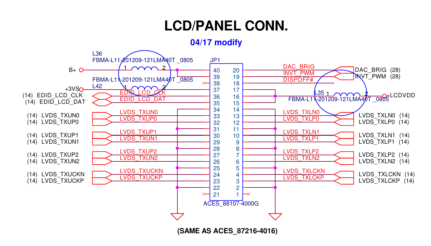
Yep, seems like we're in luck - schematics for these are available for free! One shady Google Drive link later, and we can skim through the schematic pages and find a pinout for the LCD connector:
![]()
The B+ connection seems to come from the laptop's battery, and a multimeter check shows that it goes to the inverter board through a JST-SH 7-pin cable branch. LCDVDD wires go to the laptop panel's VCC pins, and +3VS goes to the VCC_EDID pin. DAC_BRIG, INVT_PWM and DISPOFF pins all go to the inverter board.
This is most of what we need for rewiring! This is a single-lane cable for a 6-bit panel, so, a 2x8 2mm pin socket will work wonders. An SMD pin socket will have pins we can solder to, so I'm using a 2mm 2x8 SMD pin socket on the MT561 board side.
![]()
[TODO: talk about microcoax cables and how they're significantly harder to solder to]
I decided to avoid stripping the wires I pull out of the original connector and instead plug them onto the pins, then solder them on:
![]()
Soldering: [TODO: find a non-blurry pic?]
![]()
I also added a JST-5 connector to add an inverter connectoion that'd also plug into my MT561 board nicely. Sadly, I couldn't find a JST-6 cable in my collection, so I decided to plug it in a way where I only lose a GND pin - which I already collect plenty of.
[TODO: show the JST-5 connection and the finished LVDS wiring]
[TODO: elaborate on the inverter connections]
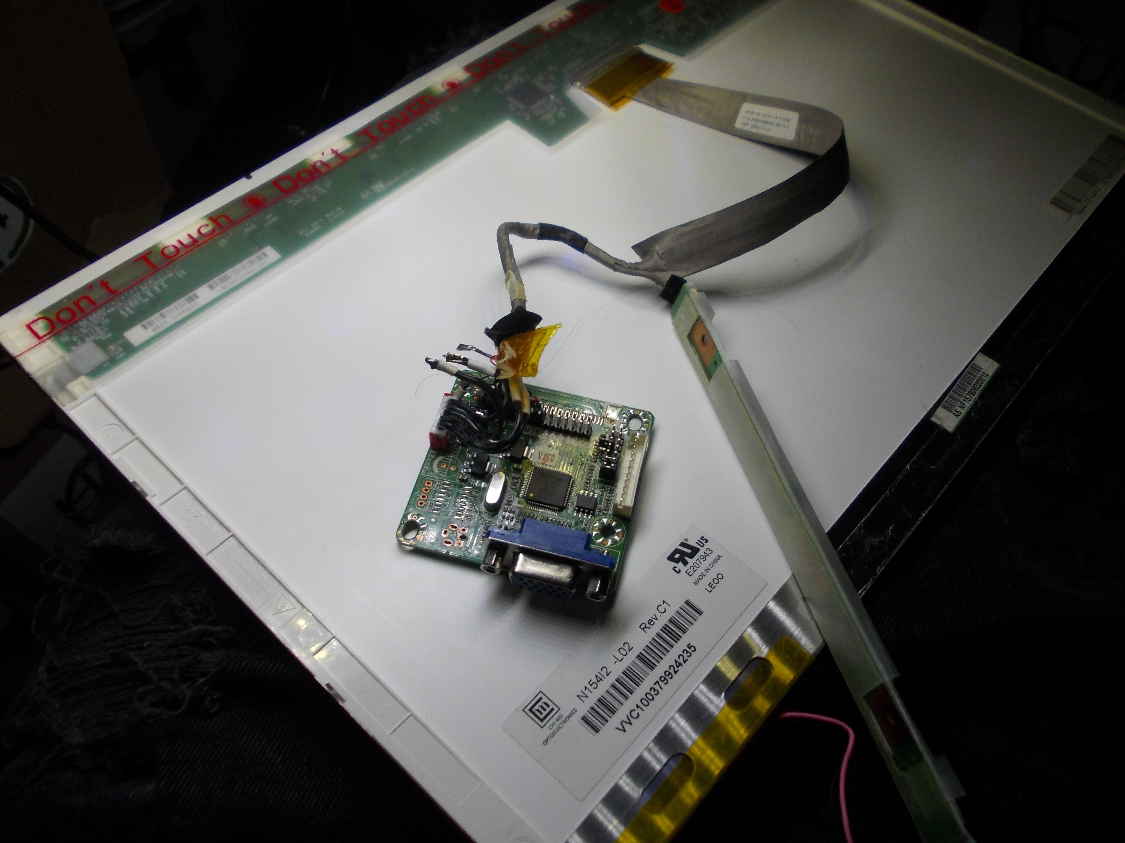
"How to draw an owl"-style, here's a finished setup:
![]()
Needs to have power wires attached - ground, +5V for the controller and +12V for the inverter:
![]()
I don't have a picture of it, but I've added 5V and 12V to it by soldering an ATX PSU female plug to these three pins. In its current state, the MT561 board shows an image on the screen, but the inverter doesn't work - once I find time to make it work, I'll finish this post.
[TODO: describe bringup and solving the inverter troubles I have]
All About Laptop Display Reuse
LVDS, eDP, connectors and controllers - let's learn it all