-
2021 Hackaday Prize Final Round Compliance Matrix
10/20/2021 at 07:08 • 0 commentsa. Build a working prototype of your project.
2 versions of the project have a working prototype.b. Create a video, between two (2) minutes and five (5) minutes in length, that shows a working prototype.
1. Link to the video
https://www.youtube.com/watch?v=Kkc7uRNK-7g
https://www.youtube.com/watch?v=1yJe9hJgmXo&t=33s2. Post high-resolution photos of the project inside and out
Pictures added3. Update and add detail to information entered during the Challenge Round
Project logs includes also the design decisions4. Show at least ten (10) Project Log updates or at least ten (10) Build Instructions updates
More than 10 project logs and 2 Build instructions video added5. Post a components list that is complete with a bill of materials for one unit
V1 Component List : https://hackaday.io/project/179878/components
V2 Component List : https://www.notion.so/nuri2/d492fa35384c4d558effe04ad1d0bc20?v=865edb5cd0f148efaba7c5b1587cf5276. Post reproducible build instructions
V1 Build instructions : https://www.youtube.com/watch?v=lWvLCNzx_zM
V2 Build instructions : https://www.youtube.com/watch?v=BKYNRNaFocUAssembly Manual:
https://github.com/makerstorage/pnpAssist/blob/main/V2/Assembly_manual/Assembly_manual_v2.pdf.pdf
7. Post complete schematics and documented input and output requirements and specifications for your module/design
Controller Board schematics :https://cdn.hackaday.io/files/1798787695900352/main_board.pdf
Project requirements and specifications : https://cdn.hackaday.io/files/1798787695900352/PnPAssist_requirements_specs.pdf
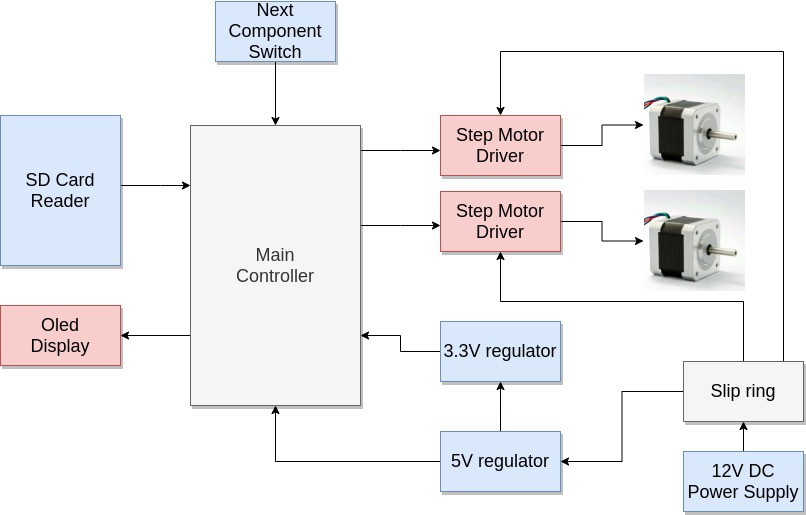
Project functional block diagram and input / output Definitions: https://hackaday.io/project/179878-pnpassist/log/196185-functional-block-diagram8. Publish all design files including Gerber files (req – RS274 / RS274X), STL files (opt), netlist (opt), nc drill files (req – human readable), ODB++ (opt), STEP (opt), PCB files (opt), or any other design files
All design Files for V2 : https://hackaday.io/project/179878-pnpassist/log/198213-pnpassist-v2-source-files -
Controller Board Schematics
10/18/2021 at 07:43 • 0 commentsThe PnPAssist Controller Board is same for V1 and V2. You can find all the eagle source files here: https://github.com/makerstorage/pnpAssist/tree/main/Controller/hardware
I also added the pdf schematics below:
https://cdn.hackaday.io/files/1798787695900352/main_board.pdf
-
V2 Components List
10/12/2021 at 08:12 • 0 commentsWe have produced 10 kits for early adaptors. And this list is the one we have purchased. You can find out the real costs of each item and the link you can also buy one for yourself. We decided to prepare the kit in China so the links are from Chinese suppliers.
https://www.notion.so/nuri2/d492fa35384c4d558effe04ad1d0bc20?v=865edb5cd0f148efaba7c5b1587cf527
-
PnPAssist V2 Source Files
09/27/2021 at 07:35 • 0 commentsI have published all the source files including assembly manual and build instructions video for PnPAssist V2. In order for you to find out the related files easily I decided to link them here in this project log.
-
PnPAssist V2 design decisions
09/20/2021 at 11:12 • 0 commentsI had very good results with PnPAssist V1. However, I saw that there were some opportunities for improvements and started working on the design of V2. The main reason for V1's design change is Center of Mass (CM). The stepper motors are the heaviest part of the system and both motors are positioned at the rear and pulling the CM towards them. However, the CM must be on the main rotary axis, which is in the center. In order to make the CM in the center I decided to place the motors on each side to balance the system.
The other design change needed is because of the center main gear. This 3D printed part works well, but it is obvious that it will wear out over time due to the large frictional forces on it. This part must be manufactured from metal. However, it will be difficult to manufacture due to its unusual and low tolerance structure. In my new design, I decided to use a timing belt because it was cheap and accessible. With these design considerations here is the design of the V2:
-
Functional Block Diagram
08/04/2021 at 08:11 • 0 comments![]()
User Inputs :
The user provides a mount file (PnP file) stored in an SD card. This file contains component names, values, coordinates and angles all of which are input for the controller.
The other user interaction with the device is pressing the next component button. This input triggers the controller to read the next line from the mount file and moves the motors to the position to center the next component that will be placed on the PCB. The controller also display the name, value and package of that component.
Mount File Inputs:
The mount file contains the following data and the controller reads this file line by line and generates the following outputs.
Input Output Name, Value and Package of the component Display on Oled Display X, Y Coordinates of the component Motor pulses after kinematic calculations. Angle of the component Controller does nothing. User rotates the machine at the main axes to feel comfortable before placement. Power Inputs:
This device requires 12V DC power and around 1 amps current. There are two voltage regulators 5V and 3.3V for the on board peripherals. In order for the cables not to disturb the user, the power is transferred to the board with a small slip ring.
Outputs:
Oled Display
Display the name, value and the package of the component to the user in order to help to pick it up from the component storage.
Motors and Motor drivers
Performs the movement to center the next component.
-
Failed!
08/03/2021 at 06:56 • 0 comments![]()
Failed!
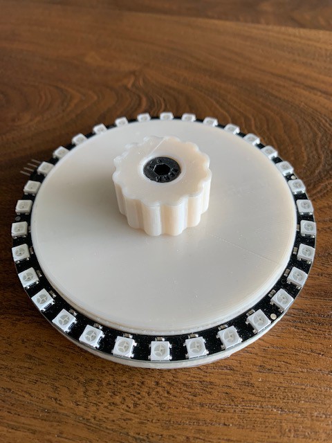
The neo pixel component box did not worked with the current firmware which heavily rely on interrupts. The single-wire control protocol used by NeoPixels requires a very steady data stream at 800 kilobits per second. Bits must be issued at a precisely controlled rate. We are also generating pulses for motor driver, we have I2C oled and SPI SD card on board. It is not easy for Atmega328 to handle all this time critical processes.
Solutions:
- We can use Dotstars (APA102C and SK9822) which use a two-wire SPI-like protocol. It has no specific timing requirements, which makes it much less demanding to drive. Either a hardware SPI module or a bit-bashed equivalent can be used.
- We can use another micro controller like arm based systems that has extra timers for this time consuming process.
- Or we can work deeply on the firmware to find out a better software solution.
I will choose none of them. I am working on the mechanical design of the PnPAssist V2. I have better ideas for the component box. if i need to give a hint it will be a carousel!
-
Main rotary axis bearing changed
07/26/2021 at 17:17 • 0 commentsI have change the main rotary axis bearing to
16010 bearing 50x80x10
The old one is not precise enough under microscope.
The BOM updated
-
2D Files Added to Github Repo
07/26/2021 at 17:10 • 0 commentsI just added the 2D files for sheet metal parts. You may need to countersink some holes for proper assembly.
### Material and production
Laser cut from 2mm Aluminum -
Better Main Gear Design
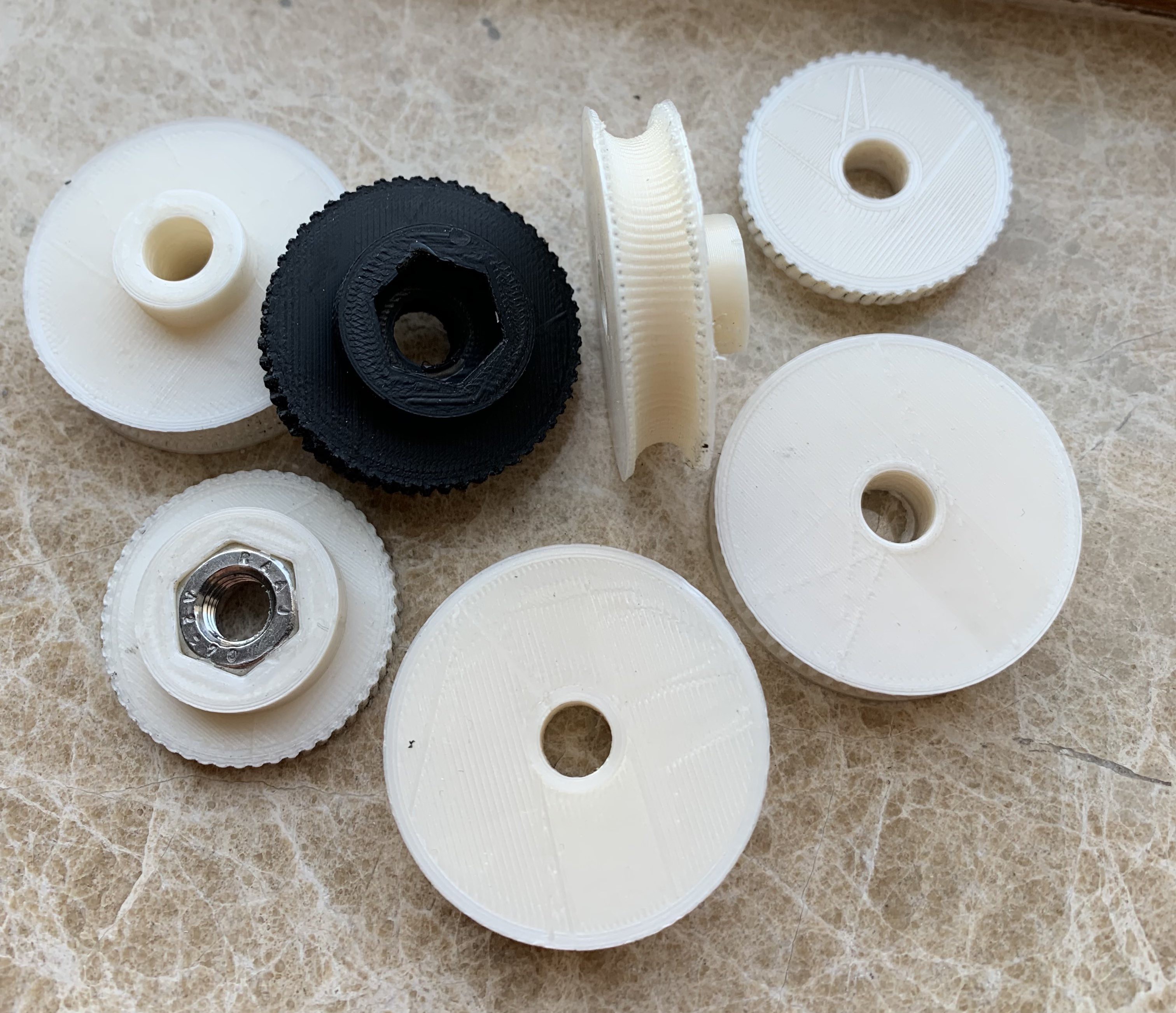
07/24/2021 at 12:25 • 0 commentsI tested so many different designs for the main rotary gear. I am glad where I am at the moment. It took my time to get an accurate design point. I updated the github repo with the final design
![]()
![]()
 Nuri Erginer


