 Anton Poluektov
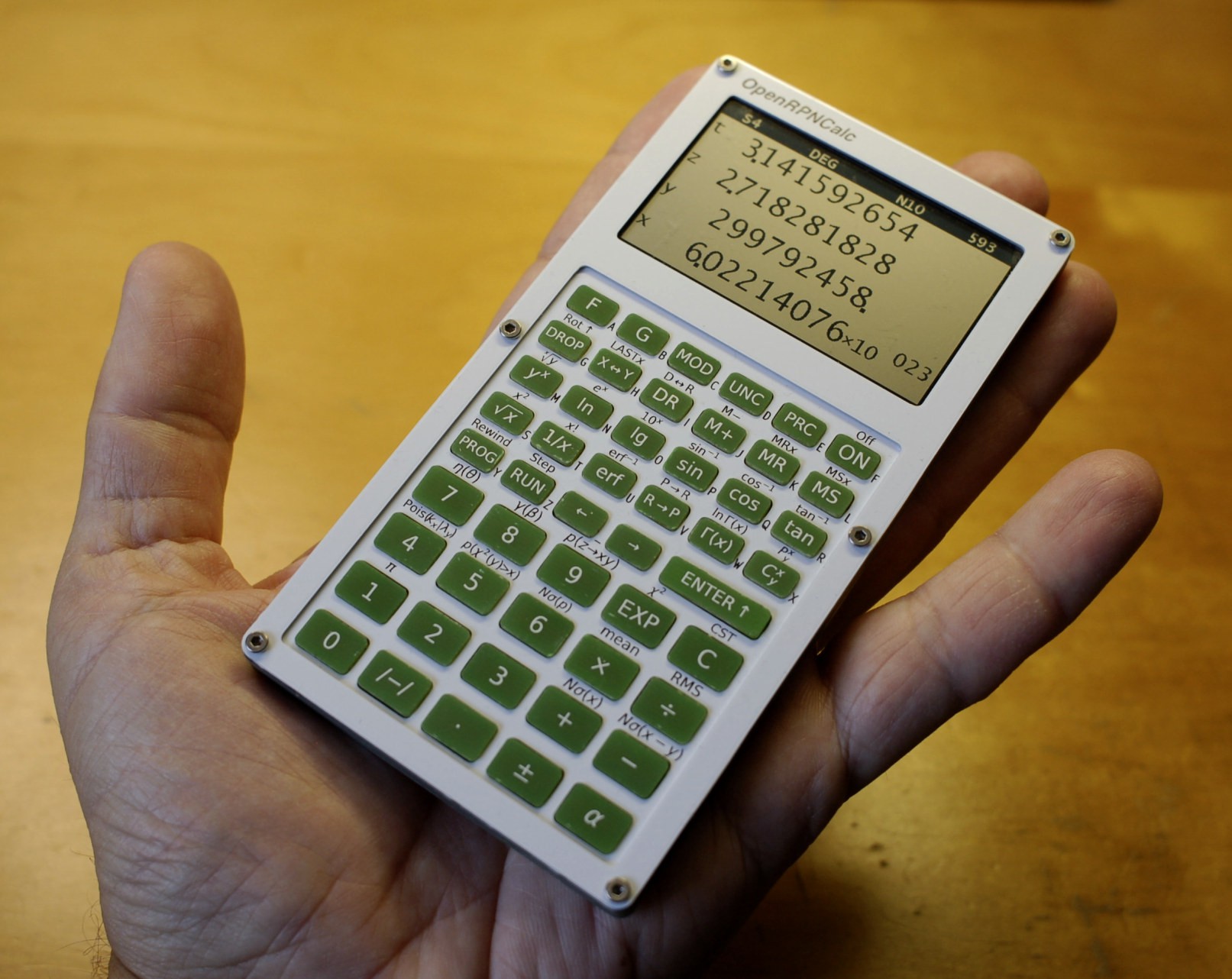
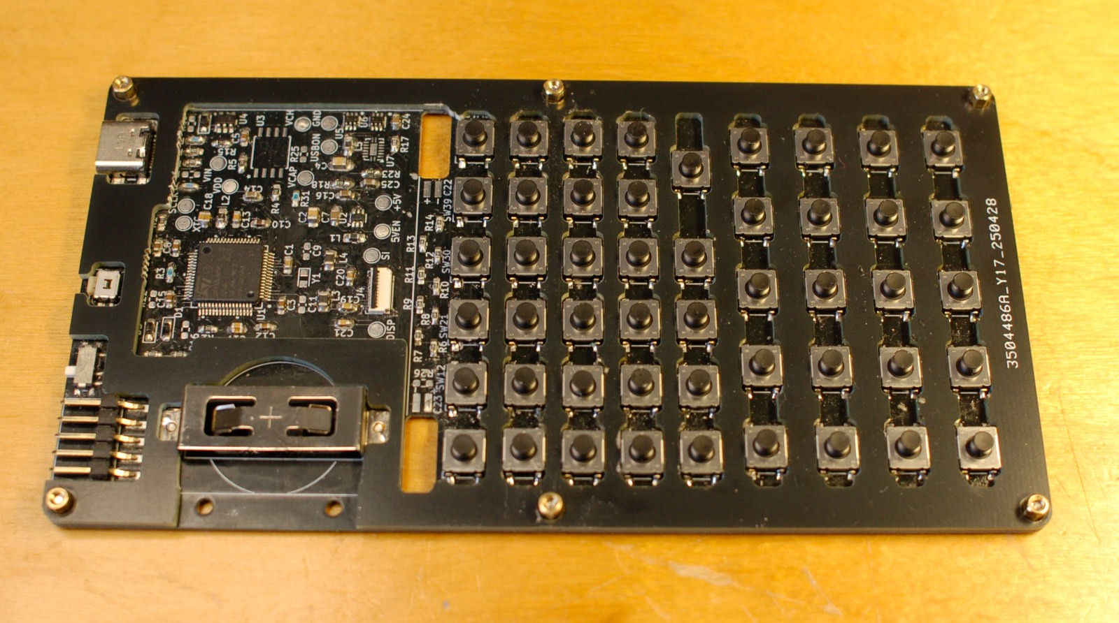
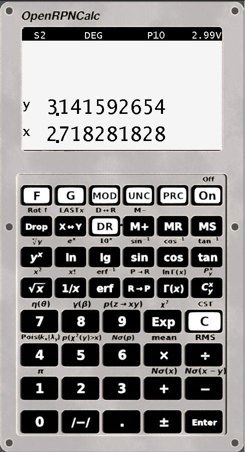
The calculator is built around a low-power 32-bit ARM microcontroller, the STM32U385. The display is a Sharp memory LCD module, the LS027B7DH01 (400x240 pixel monochrome). The keyboard uses light-touch tactile switches, specifically the Panasonic EVPBT1C4A000 (50g actuation force). All electronics are powered by a 3V lithium battery (CR2032), which should be sufficient for several years of operation.
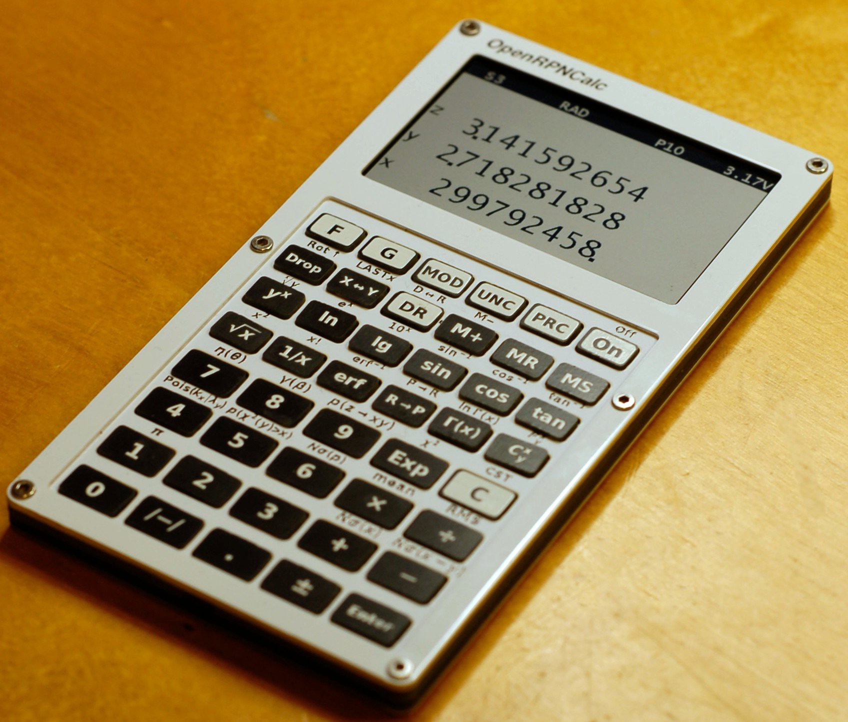
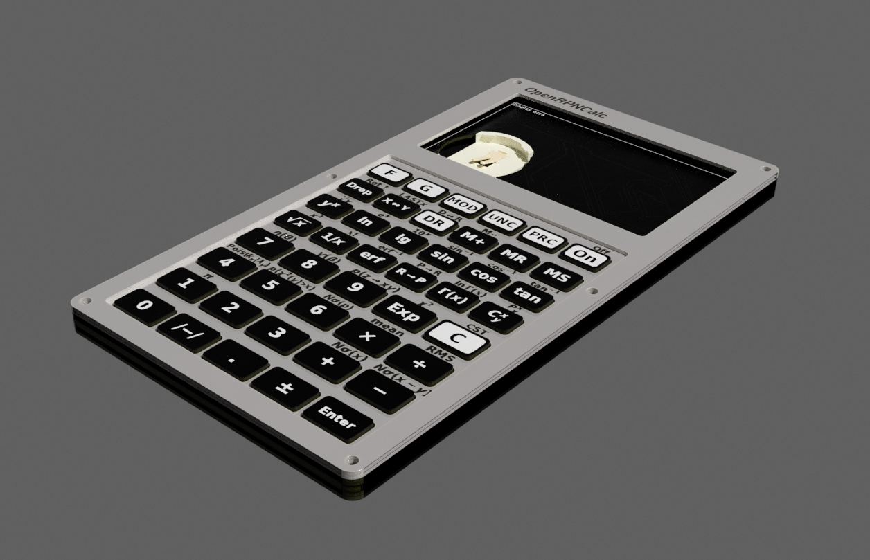
The enclosure is designed as a stack of multiple PCBs. The front and back panels are aluminium PCBs with a white solder mask and black silkscreen. The keys are also made of PCB, with labels printed as silkscreen. All components are kept together with six M2 standoffs and twelve flat-head screws. The enclosure dimensions are 139 x 73 x 8 mm.
The calculator features:
- Reverse Polish notation with a large stack (up to 100 elements)
- Double-precision arithmetic
- "Standard" scientific calculator functions (trigonometric, logarithms, exponentiation, square root and power)
- Error function (erf) and its inverse (erfinv), Gamma and log(Gamma) functions, combinations and permutations, p-values for Poisson, Gaussian, and chi-squared distributions
- Fixed, scientific (SCI) and engineering (ENG) display modes (including SI prefixes in ENG mode), with adjustable precision from 3 to 10 digits
- Calculations with uncertainties using error propagation (UNCERT mode) - a feature rarely found in software calculators and almost unheard of in hardware calculators
- Formulas from relativistic kinematics (centre-of-mass two-body decay momentum, conversion between angle and pseudorapidity, beta and gamma factors)
- Statistical functions: mean (or weighted mean in UNCERT mode), RMS, chi-squared of a series of values (only in UNCERT mode).
- 100 memory registers
- Power consumption: 0.6mA running at 16MHz, 16 uA in standby mode with the LCD on, and 5 uA with the LCD off.
- 49-key keyboard with a wide Enter key similar to HP48
- Optional HP48 keyboard files, with the aim to run DB48x (this is still very much WIP.
Check out the online emulator here.
All the documentation, PCB design files and firmware code are available on github.
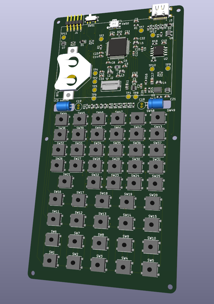
 It's a usual FR4 PCB with a black mask and white silkscreen that would cost you a few bucks in a typical cheap PCB prototyping service. The problem is, my service insists this is a panelised PCB with 44 different designs in it (why not 45, don't they count the frame?) so they ask like 20 times more for this one compared to the other boards of the same size. I agree it's a bit of a stretch to call this a PCB, as it requires a lot of milling and so on, but x20, come on!


 The plastic part of the pins exactly matches the height of the tactile switches that I used (2.5 mm). Skipping forward, it appeared that the keyboard works better without the pins, but possibly my mistake was that I left too tight a gap between the front panel and the top PCB of the keys (around 0.2mm).


 bobricius
 C. Scott Ananian
 Stephen Harrison
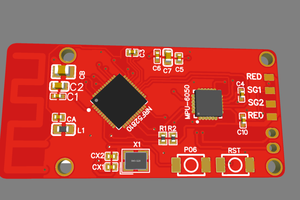
 UltraReidar
Could you perf the key PCB with via that aren't plated then you can just snap them off(I think that what they do in projects with PCD with parts you can break off) and then sand the edge smooth.
looks like there was a hackaday article about it Best Ways To Make PCB Breakaway Tabs, Revealed | Hackaday