LordGuilly
-
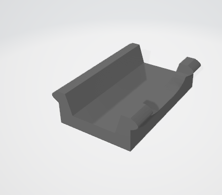
LED Strip frame
06/12/2021 at 11:17 • 0 commentsThe frame is based in a common 3d printer chain accessory, for holding the cables.
I had to adjust it a bit:
- made it longer so it matches the distance to have the right aspect ratio.
- added a side strip to fit the PVC bars where the LED strips will be placed
- split the top, which is a separate part. This way the assembly and maintenance of the wiring is much more easier, as the LED strips can be mounted, and then the cables soldered.
Parts are in Thingiverse
https://www.thingiverse.com/thing:4884051 -
Source code for the STM32 available
06/09/2021 at 18:34 • 2 commentsIt probably still needs more tidy up, but I uploaded the code to Github.
At the moment, it's expected to be uploaded to the Bluepill by the dapboot bootloader, so the "make" output won't work out of the box.
The steps would be to flash a FW image of the dapboot bootloader to the Bluepill with the ST tools , and the use the DFU tools to flash the application.
It sounds unnecessary complicated for a development stage, but it's a better solution in the long term, as it will allow normal, non technical users to upgrade the FW.
Hopefully will be able to upload more instructions and tidy up some things in the next couple of days
-
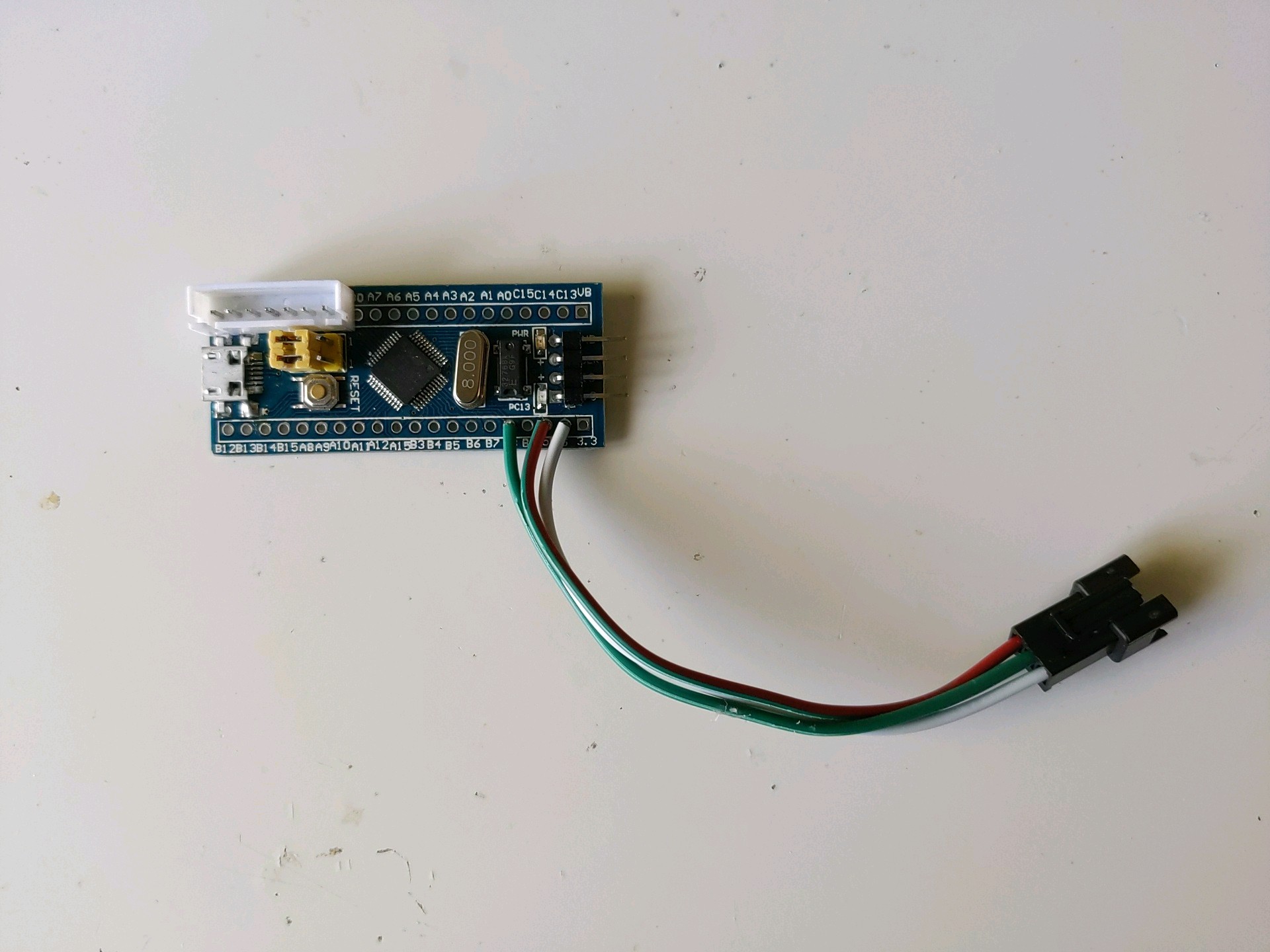
STM32 BLUEPILL CONTROLLER
06/08/2021 at 12:14 • 0 commentsBluepill based CPU. Tried to keep the wiring and soldering minimal, I think it was a good result!
The board is powered from the LED strip connector, and the 7 pin header is for the buttons. As that side of the board has 2 ground pins and a 3V3, I used for pulling up/down the input buttons.
![]()
-
The LVGL project library
06/06/2021 at 09:36 • 0 commentsThe scoreboard graphic requirements are simple, as it's just a couple of digits. But I didn't want to reinvent the wheel, so started looking at the available libraries in the internet.
Basic requirements were
- simple primitives for displaying numbers
- availability for embedded systems, or easy to port if not
- small memory footprint.
It's not that I did a massive research, as I quickly found the LVGL project, which ticked most of the boxes. The website (https://lvgl.io/) described it as "GUI" oriented, and showed a lot of fancy things that I didn't need, but I decided to give it a go.
The library resource used for the digits is called label, and each one need its own style defined. There is a hierarchy of styles, and they are inherited, so with one style per label, the individual colours or effects can be achieved.
A label can be altered/changed wtih an animation. It's a simple way to, for example, move in, move out, scale, etc. At the end of the animation, a finish callback is called. By starting a new animation on it, you can do more nice and ellaborated things
Once the basic setup is done, the library requires a periodic call to a task handler, lv_task_handler(). The period between calls needs to be reported by another API, lv_tick_inc(). The handler will call a "flush" callback if the graphic buffer changed (as a result of an animation, or an event).
The flush callback is optimized to report smaller sections of the screen, to save time and memory. But that's not possible with the WS2812 driver method. So the flush callback simply sets a flag that will trigger a full display update in a different function.
-
Driving the WS2812
06/03/2021 at 17:24 • 0 commentsAs mentioned in the previous log, the WS2812 is driven by a serial asynchronus square signal of 800KHz, and the duty will determine if the value transmitted is a '1' or a '0'.
- if the signal is high for 0.8µs, and then goes low for 0.45µs, it's transmitting a '1' (duty cycle 64%)
- if the signal is high for 0.4µs, and then goes low for 0.85µs, it's transmitting a '0' (duty cycle 32%)
Now this timming can be a bit of pain to achieve if trying to do by "bitbang". By "bitbang" I mean setting level high, doing a couple of NOPS or dummy instructions, then setting it low, and so on for the total amount of bits required for all the pixels. And any interruption or asynchronous event will ruin the timming.
I saw some projects use an SPI peripheral, setting its clock in a convenient way, and achieving the duty with the data bits. It's a clever way to do it, which has several advantages, including easing a lot the CPU usage. But it also makes the required memory grow significatively, as each pixel bit demands several bits of memory.
So I went for a more basic/traditional/academic approach. The STM32F103C8 Timers can be configured to generate PWM signals on a pin, and use a DMA channel to load the following value. That way, if the LED strip is connected to the right pin, it can be refreshed with accurate timming and minimal CPU usage.
As both peripherals are quite architecture/vendor specific, they are rarely used in frameworks like Arduino or Mbed, and require using the STM32CubeMx tool to generate the skeleton of the application. The timer channel is configured to generate a precise 1.25µs clock signal, and the PWM value in the channel will set the duty to 32% or 64% if it's a '0' or a '1'.
I wrote the first couple of functions of the GFX_DRV module, and quickly realized the idea was not as efficient as I envisioned. Instead of 3 or 4 bits per pixel bit, I was now using 16 bits (that's the size of the timer compare register) per pixel bit. The code was simple to understand and debug, but not worth the memory budget.
Yet I decided to keep it with some extra change. The refresh procedure was split into two levels, the Timer/DMA doing one full pixel at a time, and the CPU reloading the buffer with the next pixel values when the DMA cycle was completed.
The memory overhead is now fixed to 48 bytes, independently of the screen size. The CPU, when the screen needs an updated, is required to reload the timer buffer every 30µs, which is not ideal. But as it's not doing anything else, it turned out to be acceptable in the end.
-
About the WS2812
05/31/2021 at 17:41 • 0 commentsThe basic building block of the project is the WS2812 RGB LED. It's a popular part used in many projects in Hackaday, because it's chip and simple.
The interface is a serial one, with a DataIn pin and a DataOut pin for connecting them in cascade. Each LED will use the first 24 cycles, and shift the rest from DI to DO so the next LED in the line can do the same.
The period of each bit is 1.25 microseconds, and the duty will determine if it's a logic '1' or a logic '0'. A low level for 50 microseconds will cause the LED to update the colour value and start waiting for new pulses (reset condition).
The LED will show the same colour until a new value is shifted in and a new reset condition happens. There is no need to periodically refresh the pixels, unless they actually change. The time between these "changes" can be any long.
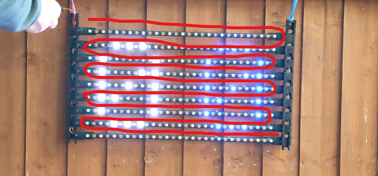
For this project, I used the IP65 strip, 5m length and 30 LED/m. As the resolution is 15x9, I have to cut each strip into 10 sections of 15 LED each, keeping the last one as spare. Sections are chained, to simplify the electric wiring, causing the data to go like a snake across the display. That way, only one pin of the MCU can drive the whole display (data flow is indicated with the red line in the image)
Because each LED needs 24 bits, and there are 135 LEDs, the total time for shifting all the information is
(24*1.25µS)*135 + 50µS = 4100µS = 4.1 mS
That's quite reasonable, even for driving the LEDs in "bitbang" mode, which will basically block the CPU for manually toggling the input pin.
-
Working prototype demo video
05/27/2021 at 20:12 • 0 comments
Portable Foldable Scoreboard
A portable, scalable and foldable display, that can be used as a Scoreboard or Timekeeper in outdoor sport events, with minimal setup