Background
Flip dot displays are amazingly cool IMHO. There has been a lot of flip dot activity posted to Hackaday and elsewhere over the years. Larry Build's 3D PRINTED FLIP DOTS is just the latest example. While Larry's project involves creating flip dots from scratch, most of the work seen out there focuses on how to wire and drive commercial display units such as Pierre Muth's 30 FPS FLIP-DOT DISPLAY USES COOL CAPACITOR TRICK and like Larry's project the emphasis tends to be on the speed that dots can be flipped.
On the flip side, these dots is are relatively expensive. New flip dot arrays can be on the order of $2 - $5 dollars per "pixel" or more. Often that number does not include the cost of control boards and power supplies. This is because each dot has an "active" element usually in the form of a solenoid that has to be powered and wired into a controller.
Proof Of Concept
So far all I've actually made is a "passive" flip square. By passive I mean has no servo or solenoid. Here is what it looks like in action:
How It Works
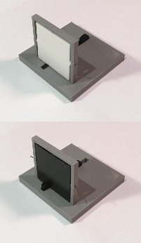
So basically this element is just plastic, a little piano wire for an axel, and four small magnets. The square has small (3 mm x 1.7 mm) magnets imbedded in the center of the top and bottom edges. The supporting frame also has magnets with the opposite polarity embedded in the same central position top and bottom.
When the slider is shifted to the front, it pushes the bottom of the square forward and the square's magnets are "dislodged" from the frame's magnets. The momentum of the push is enough to spin it 180 degrees where the magnets again take effect pulling the square into the vertical position. The pusher tab also acts as a "stop" for the square as it swings around. So white becomes black.
The opposite happens when you pull the slider back.
Thoughts Moving Forward
So it's not hard to imagine an X/Z array of these squares. Instead of having an active element on each, the idea is that a single active element (or a small number of active elements) will "visit" each square that needs to be changed and flip them. How this will happen mechanically is TBD. Think of a Core X/Z 3D printer where you replace the extruder with a solenoid or servo with a little "hand". I'm short on details at this early stage but I think that such a mechanism would not have to be nearly as precise or as solidly constructed as a printer, so hopefully a lot less expensive.
No doubt with this scheme updating the display will be slow, but with the abundance of cheap steppers and drivers and readily available software available from the 3D printer world, hopefully the cost per "pixel" would be relatively low.
 Michael Gardi
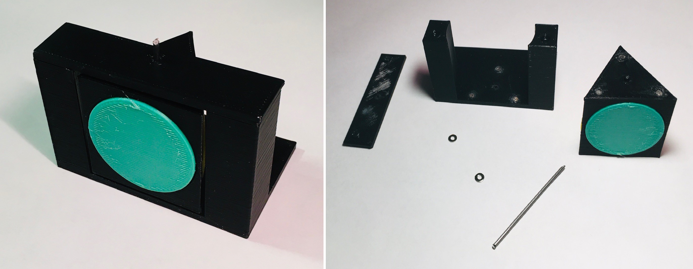
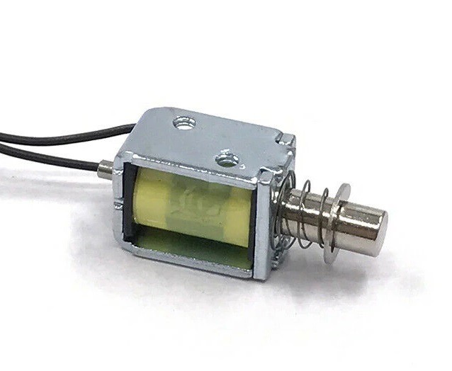
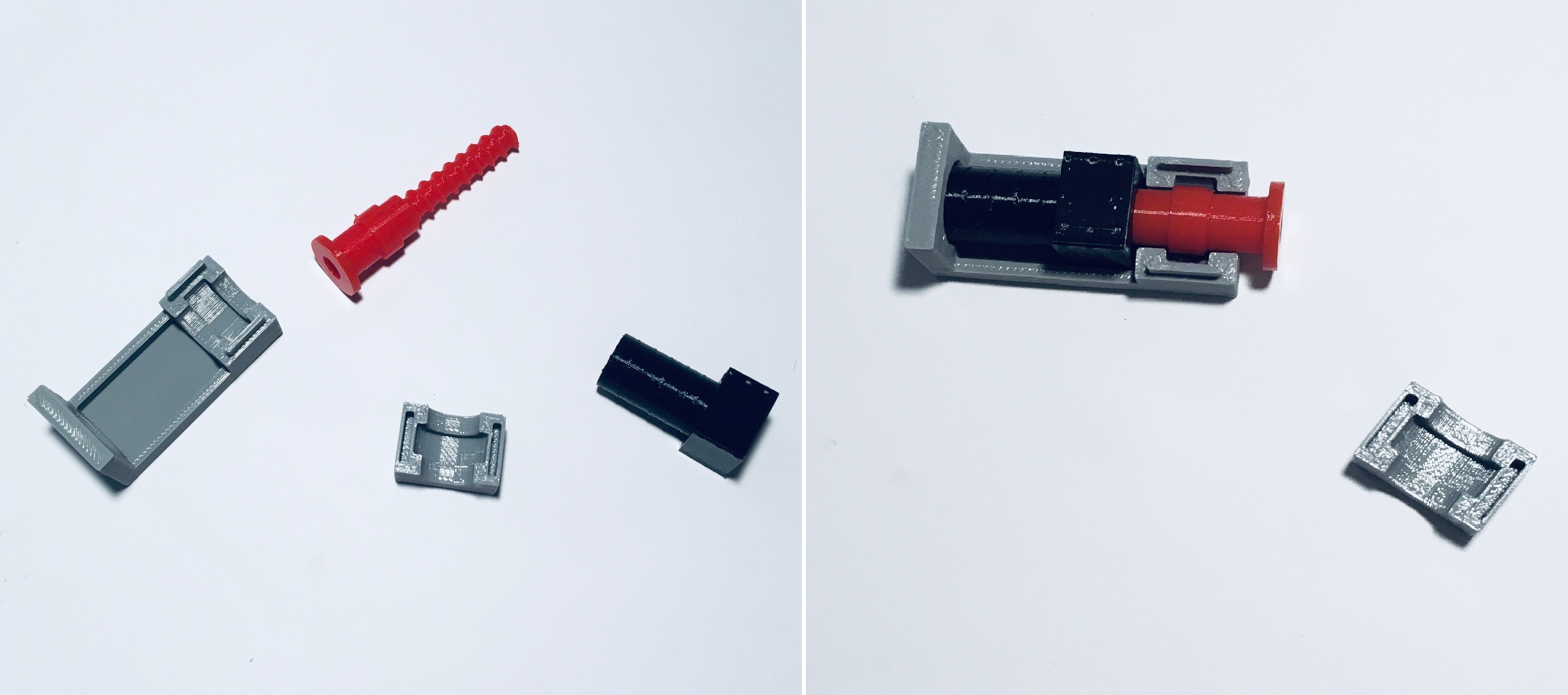



 monte
monte
 svofski
 colton.baldridge
Thanks for the encouragement John. Most of the time I have a pretty clear idea of what the end game is going to look like, but with this project I'm just exploring an idea. It's nice to know that at least one other person thinks it may have some merit ;-)
The linear clock looks really cool and I'll certainly keep the threaded rod idea in mind as I proceed.
I see you have also looked at PinThing. When I started I was thinking in terms of a single actuator, but PinThing's low cost now has me considering multiple actuators (but nowhere close to one per pixel). I'm sure there is some sweet spot to be found in terms of performance, cost, and complexity.