Cheap ROV Thruster
A 3D printed ROV Thruster based on the Blue Robotics T100 Thruster design and a cheap A2212/13T 1000KV brushless motor
A 3D printed ROV Thruster based on the Blue Robotics T100 Thruster design and a cheap A2212/13T 1000KV brushless motor
To make the experience fit your profile, pick a username and tell us what interests you.
We found and based on your interests.
Thruster - Main.stlStandard Tesselated Geometry - 9.66 MB - 11/21/2016 at 22:55 |
|
|
Thruster - Prop (Rev).stlStandard Tesselated Geometry - 1.31 MB - 11/12/2016 at 06:55 |
|
|
Thruster - Back.stlStandard Tesselated Geometry - 2.83 MB - 11/08/2016 at 22:46 |
|
|
Thruster - Support.stlStandard Tesselated Geometry - 4.29 MB - 11/08/2016 at 22:46 |
|
|
Thruster - Prop.stlStandard Tesselated Geometry - 1.31 MB - 11/08/2016 at 22:46 |
|
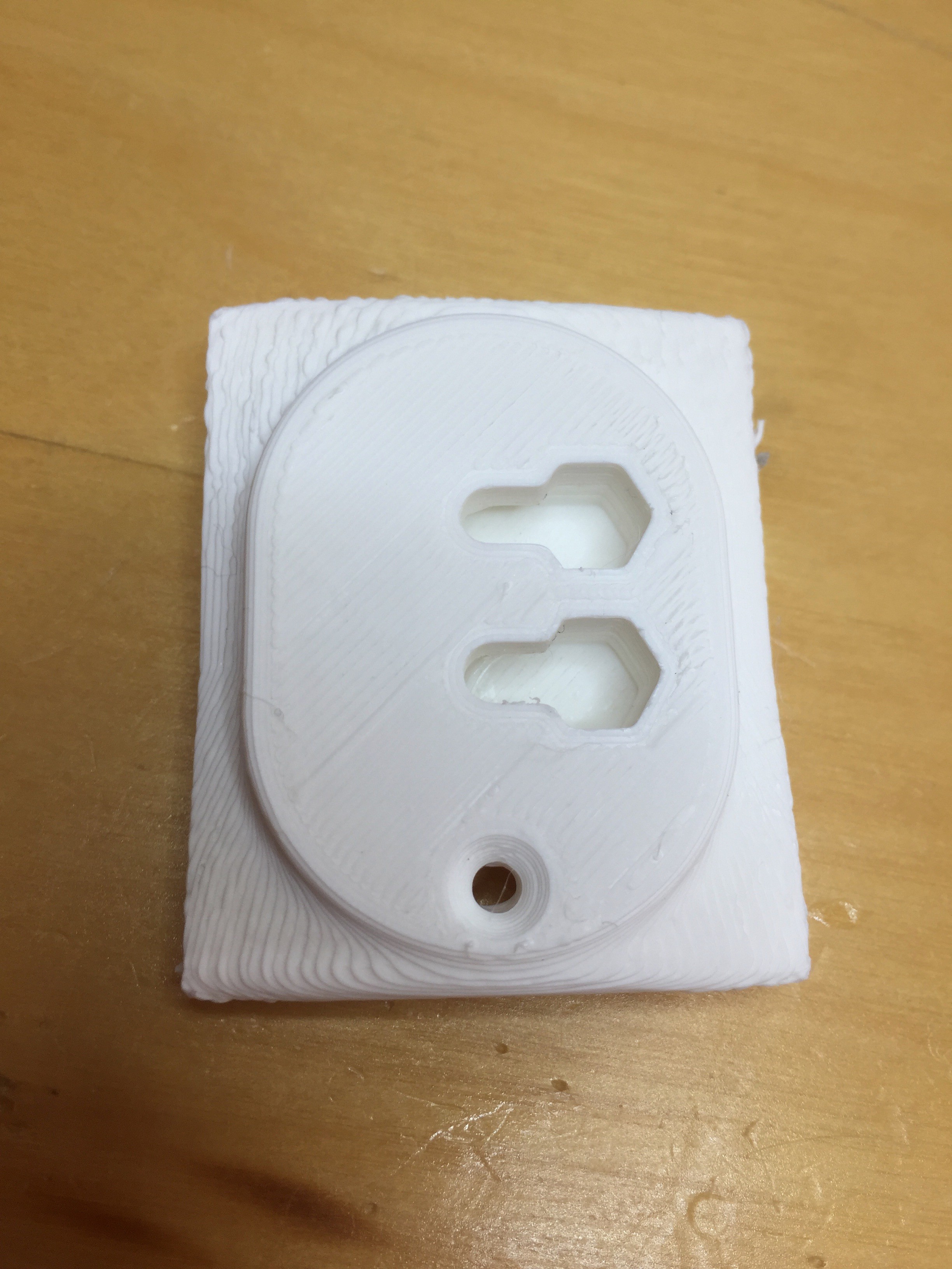
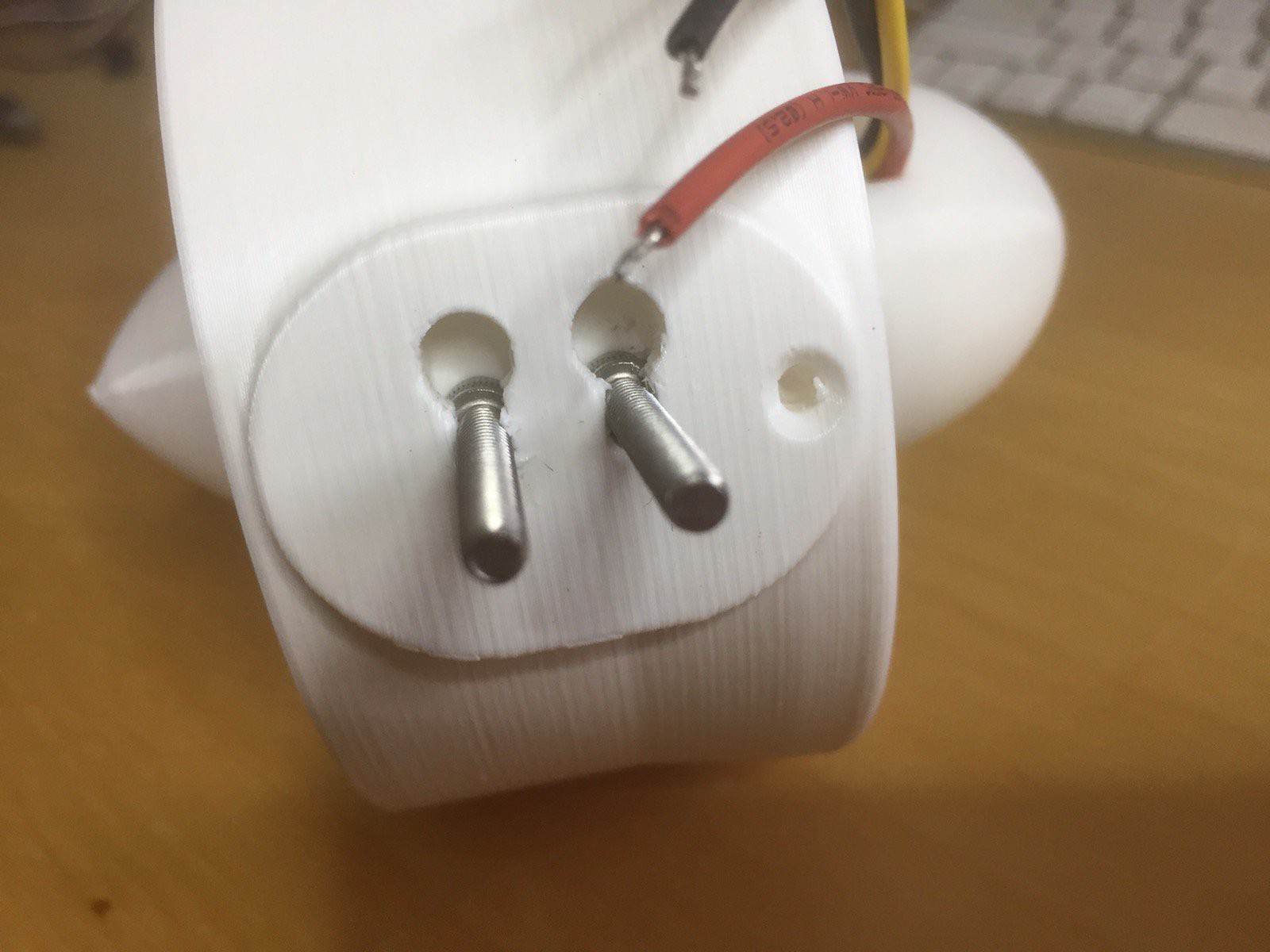
I've redesign the mounting system a little bit. Now, rather than using round headed bolts that you have to epoxy into the thruster, you can now use hex headed bolts which slot into the newly designed holes. Because they're hex shaped they will no longer rotate when you're trying to attach the thruster to your frame - even if you didn't epoxy them. It's just better.

I printed a sample piece to make sure it all works, and have updated the STL.
Added the STL for the anti-clockwise prop. You could just mirror the original prop before printing, but this save you the bother.
My ROV projects are based on the ServoCity aluminum beam system (see https://www.servocity.com/structural-components/channel/mini-channel). As such I have adapted the mounting system on the Thruster to match the spacing of the beams.

If you want to copy and edit my thruster changes to accommodate your own motor, you can find it on OnShape here: http://bit.ly/2g0tdvf
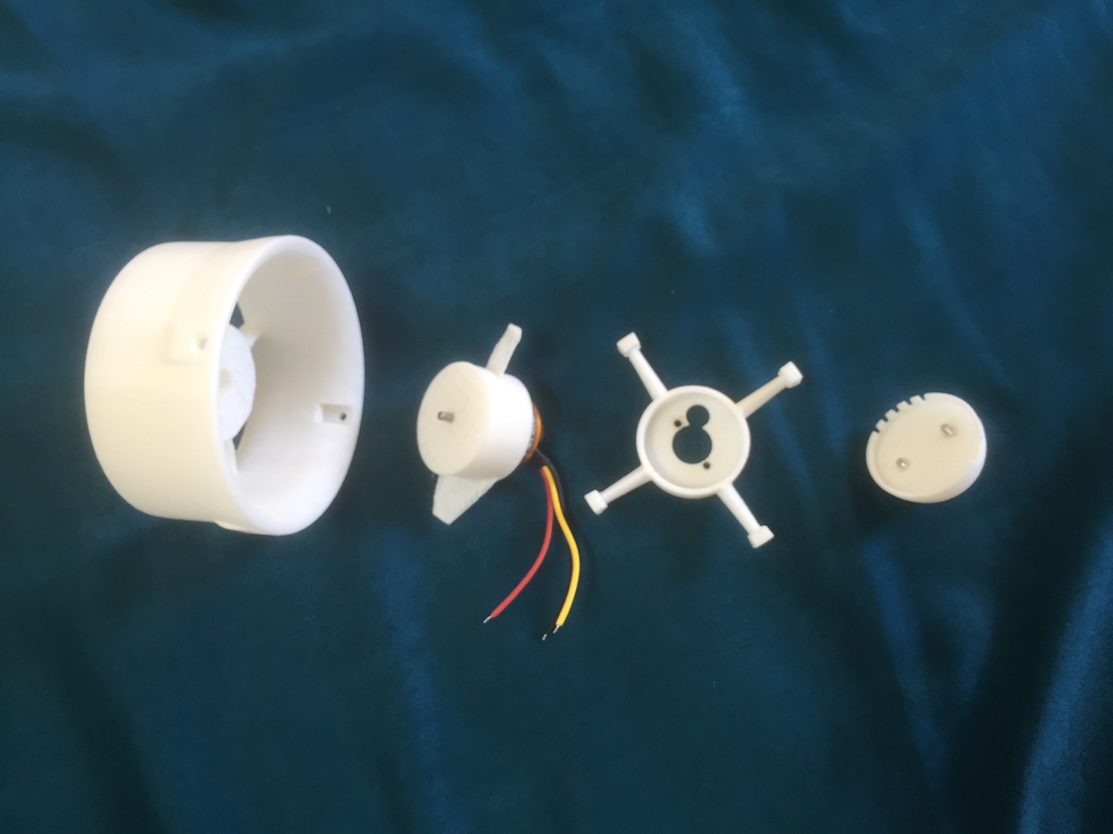
The 3d printed thruster is split into 4 pieces:

Of these four pieces, only the 'Main' piece remains unchanged from Blue Robotics design. The other pieces have been adapted to accommodate the specific requirements of my chosen motor (seen in the picture above attached to the Prop). If you choose to use a different motor, you will probably have to tweak these pieces again.
Assembly is relatively simple. The prop is pushed onto the motor (it's a tight fit and, so far, has not needed any other attachment than friction) then the wires feed out through the 'Support' (the x-shaped piece). These three pieces are then assembled using M3 bolts, inserted into the holes on the 'Back' pieces and screwed through the 'Support' and finally into the motor body. The result looks like this:

This assembled pieces is then slotted into the 'Main' part and attached with four screws.
Create an account to leave a comment. Already have an account? Log In.
Excellent work! Would you consider supplying editable cad files?
does it need any kind of sealing fluid kind of thing to stop water from getting inside
does the thing really work underwater..? i want to use this for an underwater drone project . please reply soon
I wanted to print the THRUSTERS . What is the material used to print
Amazing project, I would just like to know how deep this can go?
is it the last version that you are using in your rov project?
Thanks for all your hard work on this. I am printing one now to test fit a slightly better motor for my thrust needs, and will update you on how your printed design works out.
Well done Tim, an inspiring and ambitious project. Keep us informed on your progress and testing.
Become a member to follow this project and never miss any updates
My friend I sent you a message. Please check your message box