2021July26
I have a rough idea of modular PCB (FR4) origami starting from early 2020. The very first thing is a modular origami.
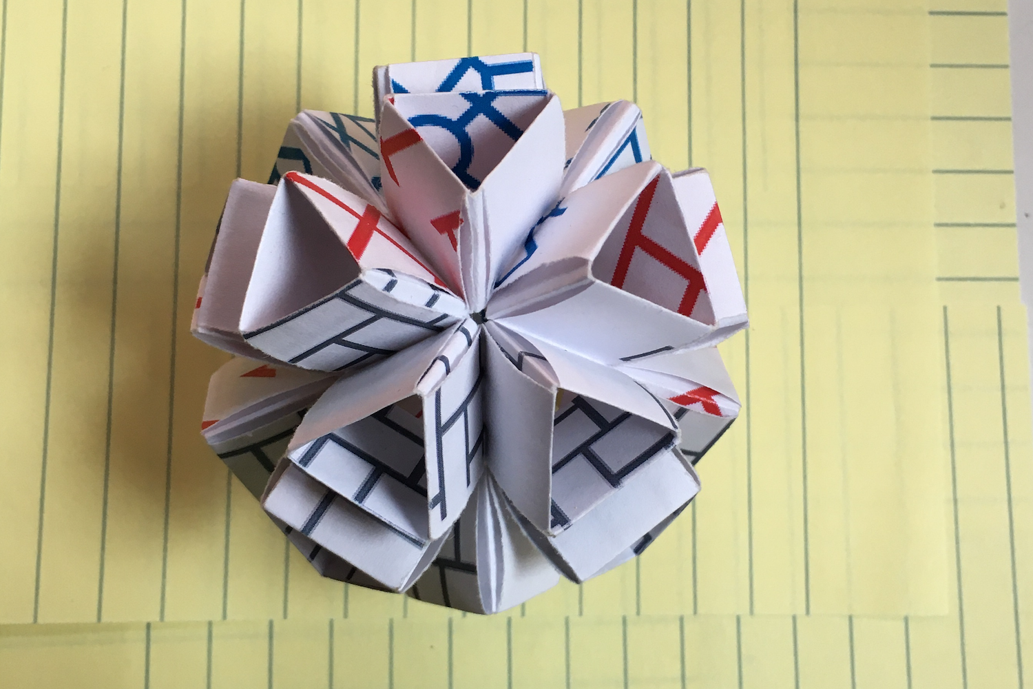
The unique design makes its assembly independent of frames or jigs. Use hardwires to connect a pair of PCB and fold it into the shape.
Already have an account? Log in.
To make the experience fit your profile, pick a username and tell us what interests you.
2021July26
I have a rough idea of modular PCB (FR4) origami starting from early 2020. The very first thing is a modular origami.
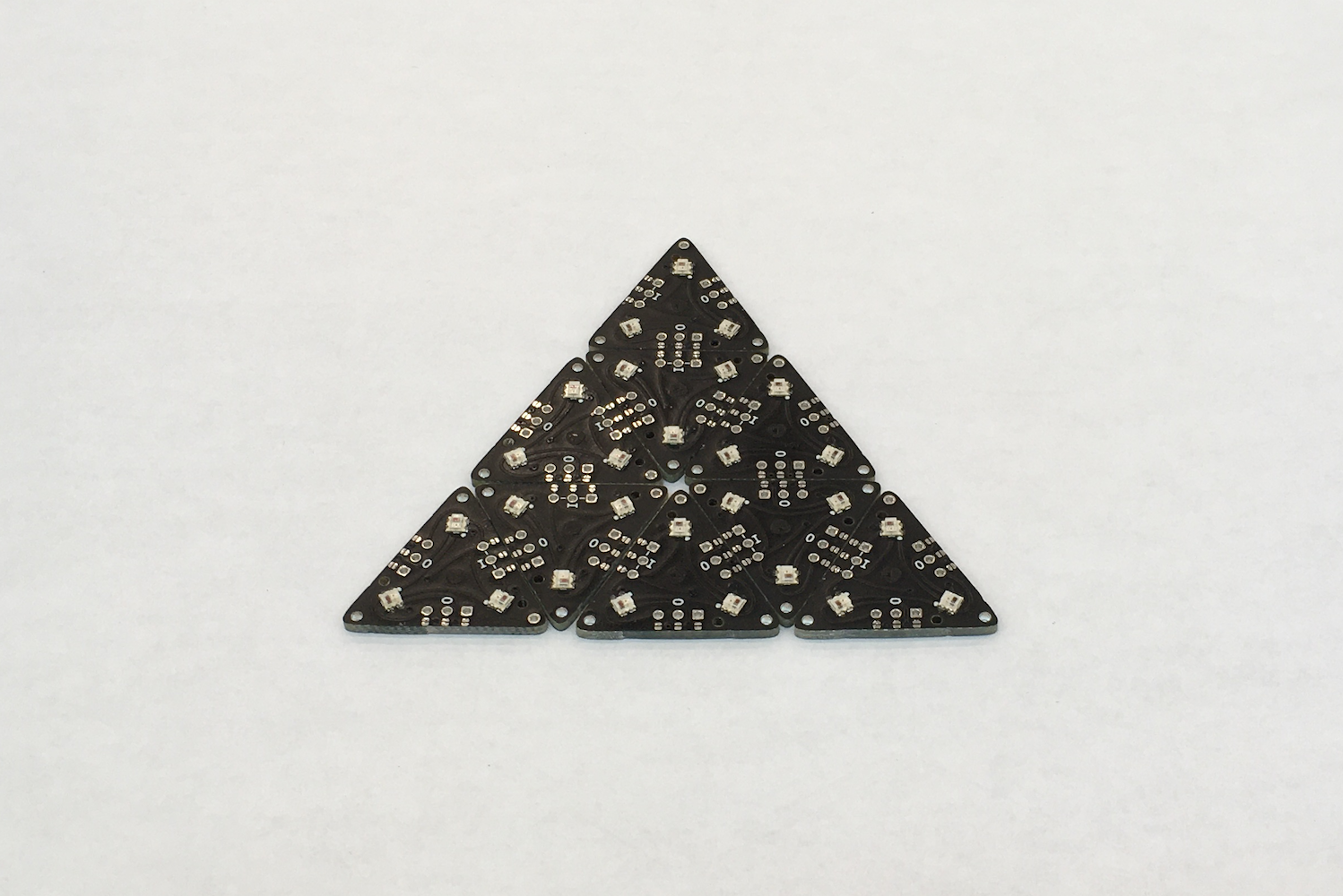
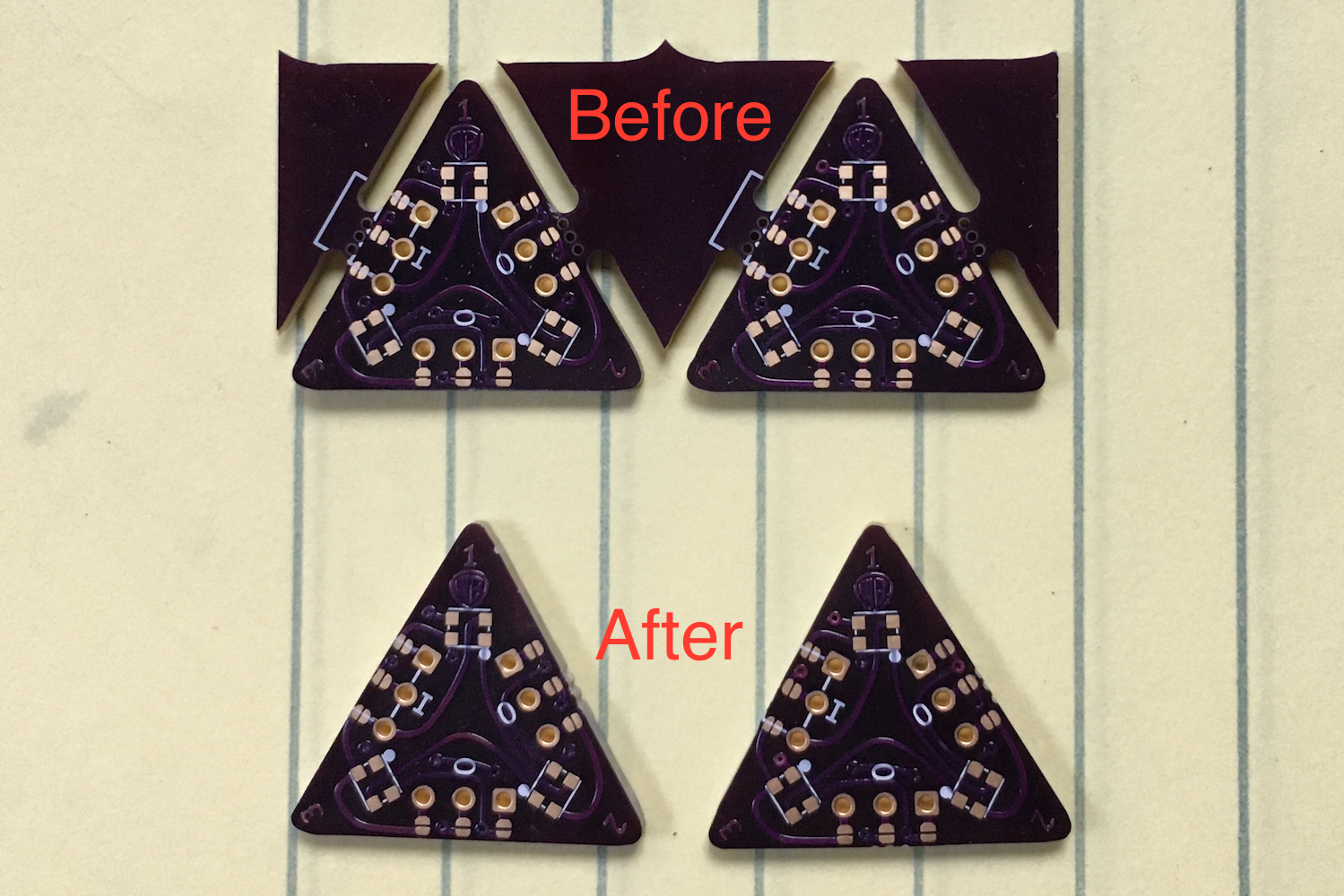
I am going to release this on Tindie this afternoon. With all edges trimmed and all LEDs preassembled, this triangle should remove a lot of tedious and laborious tasks to make a PCB origami, either 2D or 3D. Just simple through-hole soldering. Stay tuned!
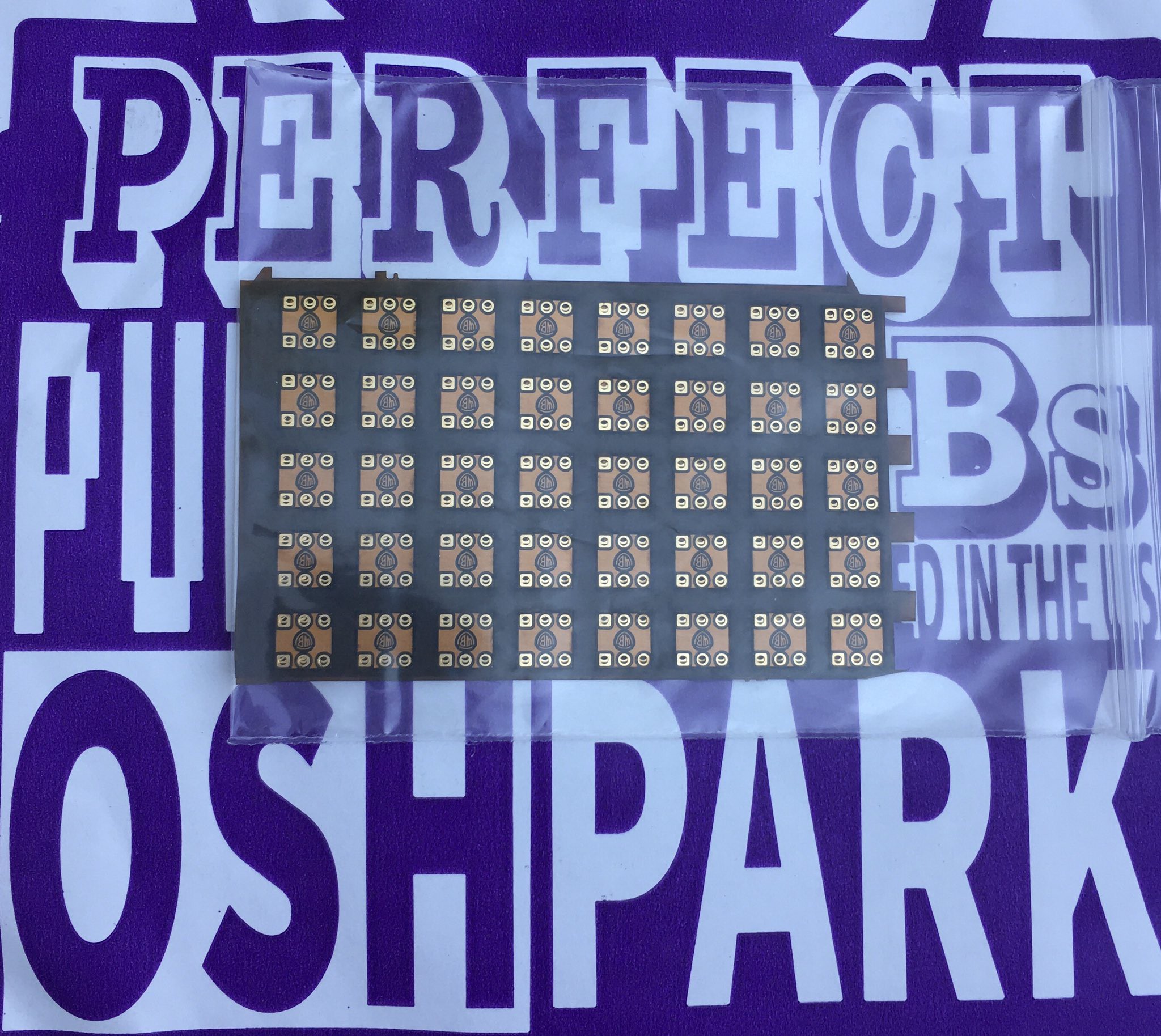
Here are some new FlexPCB received from OSHPark. This is another way to connect each module. It is easier to bend this than hardwires. But more expensive for sure. 120 in total.
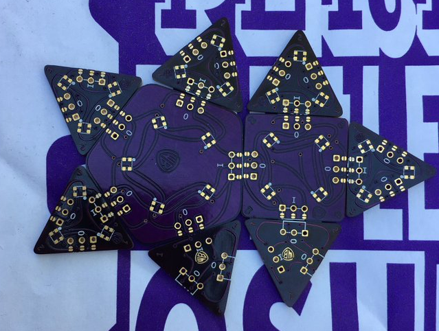
Today I have got the square and pentagon for PCB origami. The size matches with the old triangles. They are bit small for the new triangle.
I am making a bit bigger size of triangle. At the same time, the size of square, pentagon and hexagon is changed to be compatible with each other. This will take a longer time.
Here are major steps to build a DiscoBall from the triangle modules.
All the triangles comes with mouse bites in a panel. Trim the edge and make it smooth and even.
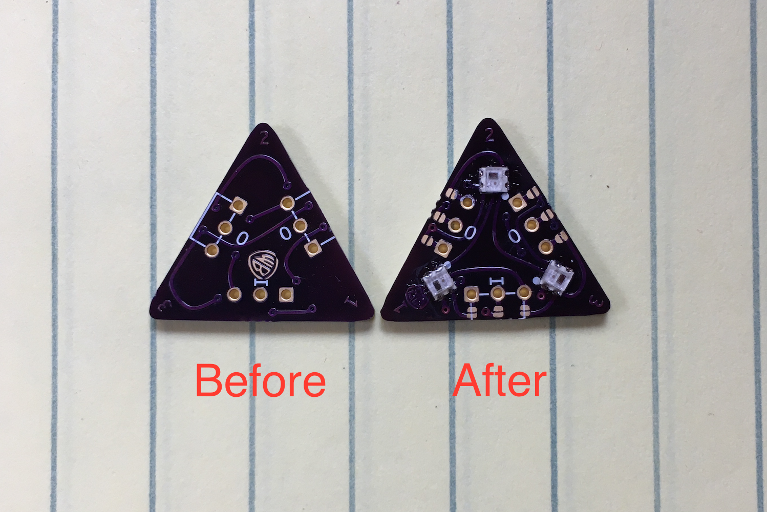
These WS2812B-2020 LEDs are not that difficult to solder. The four pads are big enough for manual soldering.

I notice that when connecting the triangles, not only are there wires soldered between the +, -, and data lines, but there seem to be little drops of solder near the edge on what looks like tiny touchpads or something. these seem to be on the output side and on + and - only. Can you explain what this is about?