shane.snipe
-
250 solder joints
08/11/2021 at 03:18 • 0 commentsOn my last punch list, I had a debug of my old build, and soldering a new build, to confirm the main double demux structure, which reads the sensors and runs the motors.
So I took apart hop along and found some of the solder joints from the flex to the header were broken, which probably resulted in intermittent connections.
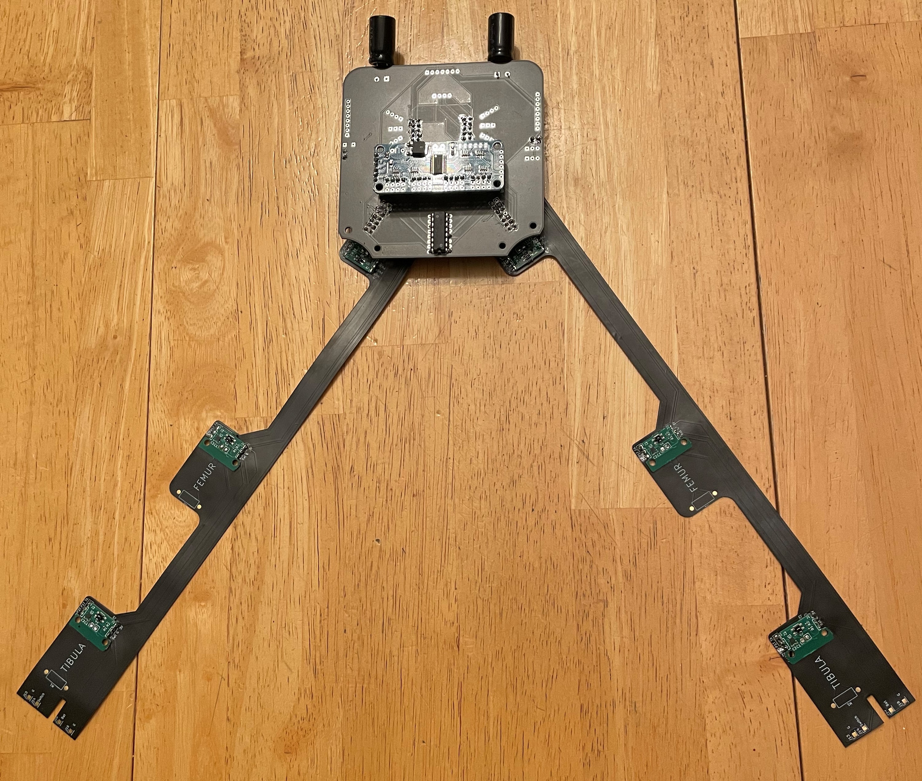
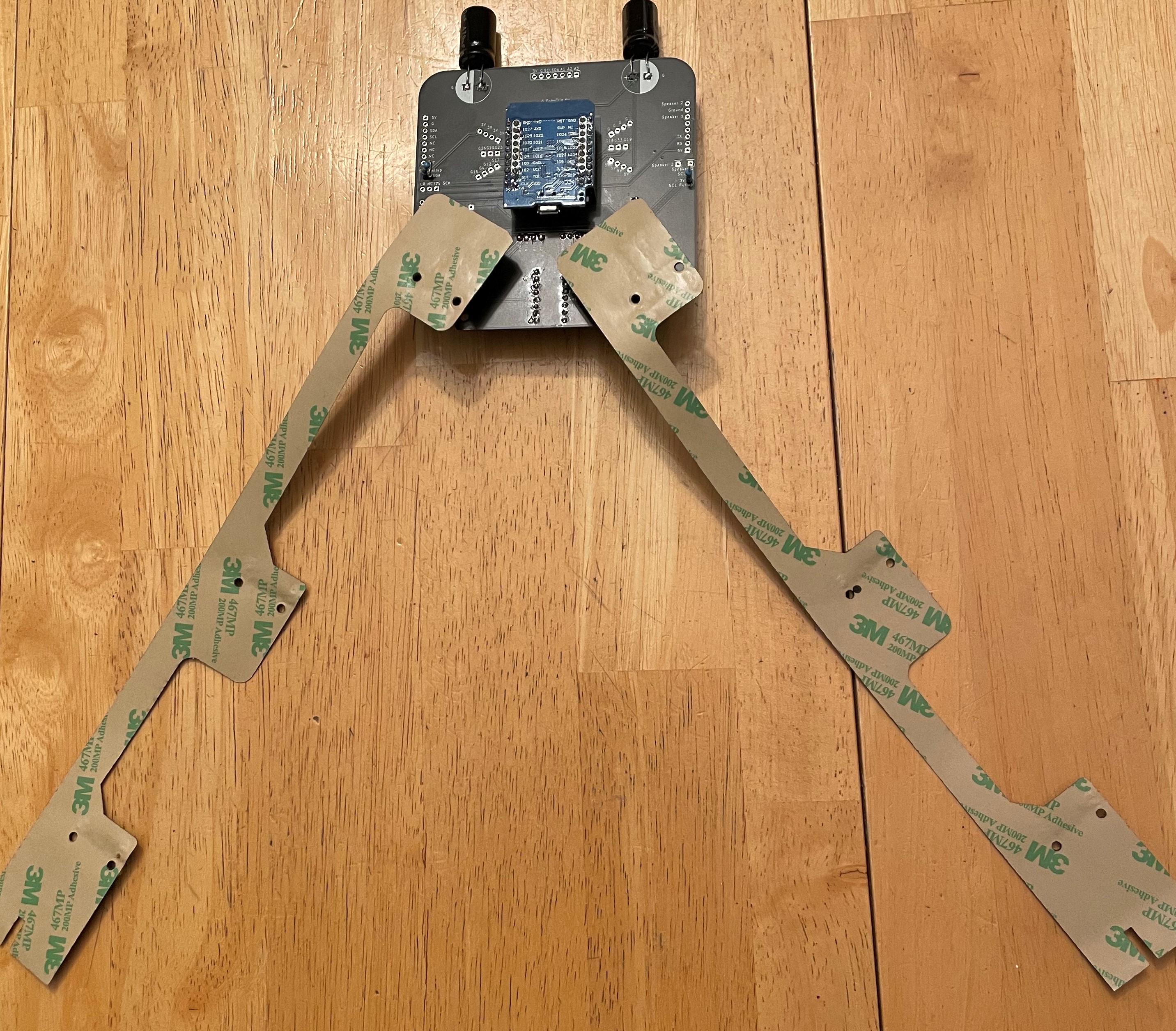
The board is being replaced, so I put headers on it so I could remove the parts, and I soldered everything up. The boards and SMD headers are going on the flex like butter now, but it still takes a half hour a flex. I put the ESP on the back and the PCA9685 board on the front so they do not overlap with the flex headers. This is fixed on the new boards but it makes me want to think more about what is hard soldered and what is socketed. I blew my PCA9685 board last time and bricked the whole device. I think the motor terminals touched the PWM pins because suddenly there were no longer any I2C devices connected to the ESP32 when I did a sweep.
Tomorrow I should connect the motors to make sure I can make them all run as I expect. I also want to check each sensor in turn through the double demux.
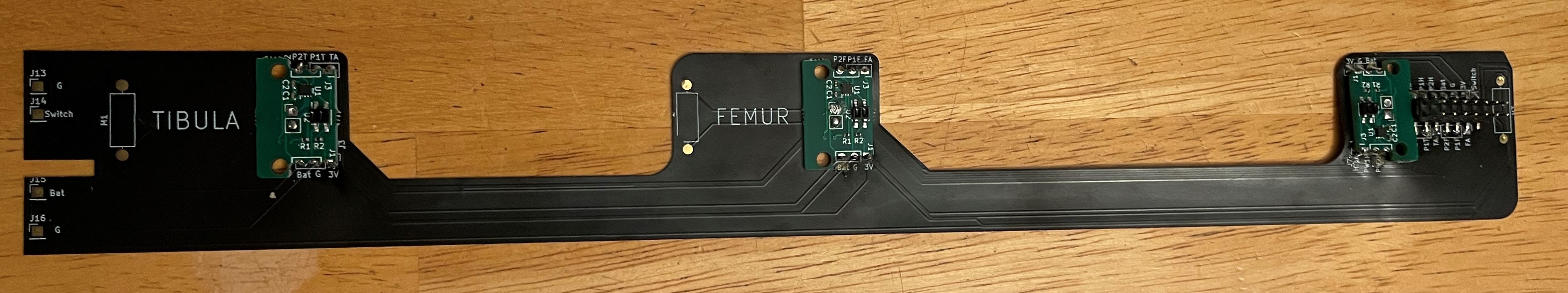
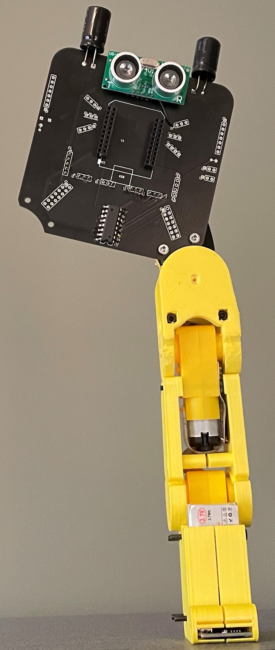
Here is what it looks like front and back before I put on the the motors and 3D printed parts.
![]()
![]()
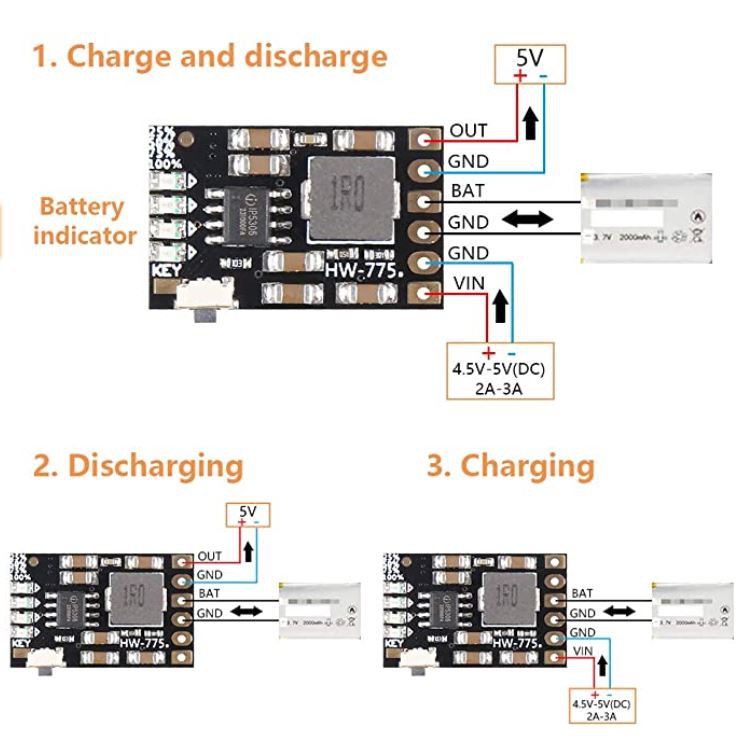
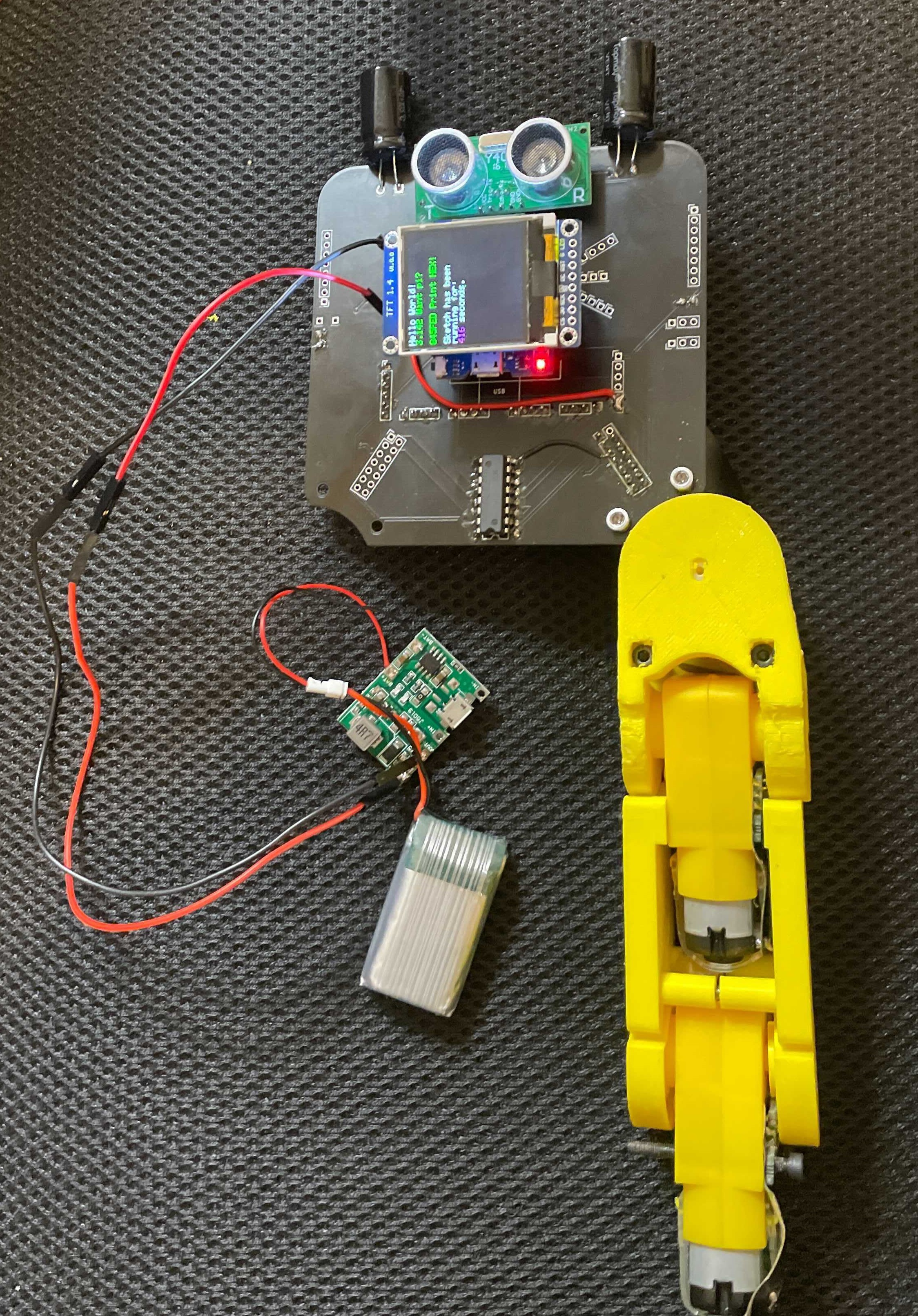
I also ordered some new battery charging and 5V boost circuits yesterday morning. They arrived today and I think I might keep the Micro USB portion outside the robot, and just connect it with some dupont connectors onto header pins coming off the battery board. The board is small enough I can put it on the flex alongside the motor and battery in the foot.
I am a little undecided about whether to put the battery in the feet or on the back. On the back I can get away with 1 2000 mAh battery and 1 charging circuit. It reduces the price by $5. The down side is it makes it more top heavy and reduces the chances of it standing up on its own. The circuit is kind of set up so that I can go either way. I will do some experiments to make sure the motors were not moving because of a lack of juice. This would push me in the direction of the 1 2000 mAH. battery. Since it s a 3C battery, that would give me 6 amps which is more than the motors use. Here is the circuit shown on Amazon.
![]()
-
MVP and Vision
08/09/2021 at 11:03 • 0 commentsIn Fox.Build, we had a group called Entrepreneurs Anonymous. They met once a month and someone pitched an idea and the team supported them with advice. One of the key tenants was full speed and discipline should be applied to get to a MVP, a Minimum Viable Product. I both embrace and struggle with this concept. I need the focus but I still want the project to be all that it can be.
The MVP for the this project is a robot that walks, is easy to program to walk, says its name and can avoid running into walls. It should be easy to assembly and have great documentation. Initial tutorials should be made in each of the 9 lanes. (3 programs of each of mechanical, electrical and coding.)
To get there, the following debugging has to occur:
Get the electrical and physical layout of the battery chargers and batteries in the feet sorted.
Look into why the motors were only working sporadically. Build a electrical only unit that does not use 3D printed parts. Isolate the electrical to show it is working.
Build up a best case model with existing parts to debug any other issues.
Reorder flexes with above battery improvements.
Increase number of contributors and provide them with hardware.
Get the hardware to the point that it is worth providing!
Make a video describing the project.
Stretch goals within this hardware package are:
Turns. (This is going to have to be a hack because the joints were made for a quadruped so I have not yet worked out how to turn. I think I will need to use momentum. Something like a kick turn where the foot pivots due to the momentum of the other kicking foot.)
Compass implementation.
Can stand up on its own.
Use Edge AI to add voice commands.
Add an options for a repeat mode where the robot can learn as you manipulate its joints.
However, my natural inclination is to push the hardware to where it can go. Here are some ideas for hardware expansion
1) Spin the daughter board and get a second set of legs going to make it a quadraped.
2) Design a 3D printed T joint to allow smaller motors to be turned into the double shaft motors need for this design. Think ARMS!
3) Incorporate the circuitry of the sensor boards into the flex and order the flex with components. Understand the volume trade-off where this makes sense.
4) Incorporate the daughter board circuitry into a flex for I2C additions without a flex board like a tail or wings or head.
How can you tell I am a mechanical engineer. My heart is in the physical design.
-
Board Spin!
08/09/2021 at 01:10 • 0 commentsThere is something very satisfying about spinning a board. How often do you get to eliminate a fumble with a few clicks of a mouse, 8 days and $50! All in the name of progress. Better yet, you get to implement all those lessons learned and cement the knowledge in your newer better revision.
Here was my punch list.Schematic items.
4) Take a hard look at 5V and 3V. Anything running on 5V needs a level shifter to avoid frying the ESP with the communication signals. The two components that need to be 5V are the ultrasonic transducer and the DF Player. Move the Gyro to 3V.
- Added the level shifter for the Ultrasonic and the DF Player. Just used 2 6 pin headers instead of making the schematic symbol.
-Added the 5V to the board to board connector incase I want to run 5V on the other board without a battery.
- Changed the 5V to 3V for the MP6050. I think I had it at 5V because of the trouble the wimpy 3.3V ESP regulator was having but I do not think the lower power accelerometer will tip it over the edge. I have been considering adding a 3.3V regulator and not relying on the 5V to 3.3V regulator on the ESP to do anything. For this spin I am just going to move the accelerometer to 3V and put in the level shifter for the Ultrasonic and DF Player.
Here is the updated Schematic.
![]()
Now for the layout.
1) Changed the 7 pin connector to an 8 pin for the board to board.
2) Added the 2, 6 pin headers.
1) Move PCA9685 board up to avoid the interference with the leg connectors and potentially the motor.
Moved it up 8mm.
2) Narrow the pins on the Demux. Previously chose too wide a package and had to splay the pins to get it to work.
Forgot this one. Done now...
3) Use 2 ground planes and route discrete 5V power traces.
Worked fairly well.
6) Put in some through holes to allow the daughter board to be connected with some long standoffs.
Done.
Now label and ship.
-
Ready for a redo
08/08/2021 at 10:43 • 0 commentsWell, yesterday was a combination of audible groans with a triumphant upswing toward the end of the day. My wife actually asked me if I hurt myself when I found out I soldered the foot components on in a way that would only work if the foot was facing backwards.
Here is what went well:
The screen is working! I have a dream of moving limb to a position, noting the sensor value and then moving it to the next. With enough granularity, I am hoping I can just ask the robot to go to these sensor positions and I will have a walking gait without the hard work of inverse kinematics.
Additionally I was able to connect to the PCA9685 board over I2C. It is outputting the appropriate driver signals to the leg flex.
![]()
What worked after some bodge wires:
5V power to the device from a battery/step up regulator. The regulator will not go lower than 5.47V which is within the allowable voltage range for the ESP32 but I would prefer it to be 5V. I could put a diode in line which would drop it to 5V and eliminate the back voltage from the USB power during programming. However, to get the voltage working, I struggled and added wires. The 5V net is connected on the bare board but not on the one that was soldered. The 5V coming from the right leg and power pin of the ESP were not connected to the other 5V net even though I made a 5V power plane. I am considering just running discrete 5V traces on the next build and have a ground plane front and back.
Also the ground on the leg was floating. Looking back at Kicad, I saw an unconnected rats nest air wire. I had looked at the DRC errors but did not check the unconnected tab. There were grounds nearby so the bodge wire fixed that one and now I was getting nice signals down my leg.
What still does not work:
Although there were the correct signals gone to the the flex and presumable to my motor drivers, I did not get much more than some random twitching of the motors. For a while I got a consistent movement in one direction from one of the joints. I synchronized a LED pulse to coincide with the pulses from the PCA9685 board but most of the motor direction changes did not result in movement. This could be caused by broken flex connections, stick joints or general power issues. I probably should diagnose it before re-spinning the board.
I am also wondering if I can get enough power out of the 5V step up regulator. I would like to get the one from a power bank with a fixed 5V output.
Where trouble was expected but not found.
We had a lot of concerns about the 5V voltage from the battery and the one from the USB not playing well. So far, nothing was obviously wrong (read no magic smoke escaped) when both powers were connected at the same time. I was able to program while still running from the battery. In addition, I was able have the screen run all night long on a battery and it still was working in the morning. That almost sounds to good to be true. Maybe the display program turned off the wireless on the ESP to save the power but I was shocked to see it still running this morning. ( Might have had something do with a short night. I woke up at 4:30 with the PCB redesign punch list going through my head.)
What to do today:
1) Read sensors! Now that I can command the PCA9685 at will I can send the signals to the analog Demux chip and presumably put sensor reading up on the screen. In order to do that, I need to figure out how to display a variable on the screen and combine the I2C PCA9685 program with the display program. Hopefully they play nice together.
2) Re-spin board.
3) Make the daughter board with just he PCA9685, the demux and the flex connectors.
What is left untested.
1) I2S microphone. - This looks to complicated to get tested before my board spin. I will leave it and hope for the best.
2) MPU6050 Gyro - I have used this on every project I have done for years. It should be workable.
Board items to address:
1) Move PCA9685 board up to avoid the interference with the leg connectors and potentially the motor.
2) Narrow the pins on the Demux. Previously chose too wide a package and had to splay the pins to get it to work.
3) Use 2 ground planes and route discrete 5V power traces.
4) Take a hard look at 5V and 3V. Anything running on 5V needs a level shifter to avoid frying the ESP with the communication signals. The two components that need to be 5V are the ultrasonic transducer and the DF Player. Move the Gyro to 3V.
5) Implement said level shifter, potentially in the top right corner behind the ultrasonic sensor.
6) Put in some through holes to allow the daughter board to be connected with some long standoffs.
7) Add a 5V line to the board to board connector.
Flex items to address.
1) Motor terminals need to be through hole. To keep the adhesive, may 2 non plated through holes with a pad next to them.
2) Redo the charger an switch connections on the bottom of the flex. Find a new charge pump that is 5V and position the switch appropriately with wider spaced pins. Target no wires.
3) Move the through holes on the hip connection so the pads line up.
4) Consider reinforcing radii with unconnected copper planes. Seeing tearing.
-
Hop along
08/07/2021 at 10:18 • 0 commentsWell its progress.
![]()
![]()
I burned some early hours this week putting this together and although it bends the way it should and the parts come together, I have found some areas for improvement for sure.
A lot of the issues come from the fact that when I asked for adhesive on the back of the flex circuit, PCBWay decided that I could no longer have through holes. So all the through holes that I had on the circuit which was every solder joint now became pads.
Now some of those changes actually worked well for me as I found a nice SMT double header that fit perfectly on my double row of pins to connect to the board. However, I now have to make my own drill holes for some of the pads. When I pierce them the pads like to come off. So for the motor, to flex connections, I had bodge wires on half of them. Not the end of the world but an insult to my sense of order.
This further complicated the assembly of the foot which is crowded with the battery and and charger. Admittedly, I did not think I was going to hit it on the first try and I sent the flex out before I designed the boots complete. I expected to run some wires in the foot but without the through holes the wire joints are not as robust as I would like. It is pretty easy to pull the solder pad off the flex and there goes an hour of soldering and $20 in parts.
So I gave up on the sensor on the bottom of the foot, and then the battery as well. I can always connect a battery at the brain board for testing so it was just a trial. I am going to have to go back through the foot and try to make the flex, the battery and the charger board line up more naturally so it is not a 3 handed job to put it together..
The bottom of the foot is design to take a flexible printed sole but printing it is another item on my punch list. I had tried to print it in Ninja flex but I could not get a full 2mm to print without the filament refusing to feed, even though the first 5 layers seem to work. I bought some Amazon Basic TPU which is a little less flexible and I hope to print it this weekend.
Going up the leg, the flex routing seems pretty good. I have not taken the liner off the adhesive except on the bottom but even without taking it down it seams OK. The liner provides a little reinforcement which is necessary and I flip it 50 times to get the screws in. I had one radius start to tear so this is a concern. Maybe when I redesign the layout of the boots it will de-risk this assembly.
The 3D printed leg joints came together pretty well and the leg flexes well. The sensors fit under the sensor ramps well and I look forward to running some motors and testing the sensor readings today. I can solder up a flex in about a half an hour with about a 90% first time connection rate so this has improved greatly from my first flex design. I found that if I put some screws through the board and flex, it makes sure it is soldered in the right place. It makes me work harder on the soldering but the eventual assembly is at least possible. The sensor board to holes on the hip joint seem to need to be shifted. The board is not quite symmetric so when I flipped it, it did not line up as well.
In my adventures in creating through holes, I found that I I pierce below the pads it seems to be more robust than piercing through the pads. The pads are less likely to come off.
The double row of headers is pretty tight on the brain board, both tot the leg and do the PCA9685 board on the other side. To make it fit, I had to cut away the unused Pin on on the right side when looking from the front and cut away at the PCA9685 board on the left. Lastly the motor and the PCBA board are touching so none of this is ideal. It is squished like this because I was trying to stay with in the 10cmx10cm cheap limit for the JLCPCB board. I might try to move the board up under the ESP by about 7mm. This will make routing a little more difficult but it should be doable.
Other board changes that need to be made had to do with drive voltages and signals to the ESP. The ESP will be fried with 5V communication signals but the MP3 board and the HR-SR04 ultrasonic transducer only work with 5V. I forgot to include the level shifter for these devices. I will have to re-spin for this but I may as well figure out what else I messed up before I go through the effort.
Mechanical punch list.
Build other leg while document process and irritations.
Redesign foot to try to line up flex with the switch and the
Electrically, my punch list is as follows:
Move the motors
Read the sensors
Move the motors to a sensor location
Add the accelerometer
Move the motors to a target inclination.
Programming wish listOutput on a display or phone the joint sensor readings
Implement a method to record positions of interest
Ideally have the robot be able to move through a sequence by just sending it a file.
Or if it is on the device, record a set of points and let it cycle through them.
-
Hop along
08/07/2021 at 10:18 • 0 commentsWell its progress.
I burned some early hours this week putting this together and although it bends the way it should and the parts come together, I have found some areas for improvement for sure.
A lot of the issues come from the fact that when I asked for adhesive on the back of the flex circuit, PCBWay decided that I could no longer have through holes. So all the through holes that I had on the circuit which was every solder joint now became pads.
Now some of those changes actually worked well for me as I found a nice SMT double header that fit perfectly on my double row of pins to connect to the board. However, I now have to make my own drill holes for some of the pads. When I pierce them the pads like to come off. So for the motor, to flex connections, I had bodge wires on half of them. Not the end of the world but an insult to my sense of order.
This further complicated the assembly of the foot which is crowded with the battery and and charger. Admittedly, I did not think I was going to hit it on the first try and I sent the flex out before I designed the boots complete. I expected to run some wires in the foot but without the through holes the wire joints are not as robust as I would like. It is pretty easy to pull the solder pad off the flex and there goes an hour of soldering and $20 in parts.
So I gave up on the sensor on the bottom of the foot, and then the battery as well. I can always connect a battery at the brain board for testing so it was just a trial. I am going to have to go back through the foot and try to make the flex, the battery and the charger board line up more naturally so it is not a 3 handed job to put it together..
The bottom of the foot is design to take a flexible printed sole but printing it is another item on my punch list. I had tried to print it in Ninja flex but I could not get a full 2mm to print without the filament refusing to feed, even though the first 5 layers seem to work. I bought some Amazon Basic TPU which is a little less flexible and I hope to print it this weekend.
Going up the leg, the flex routing seems pretty good. I have not taken the liner off the adhesive except on the bottom but even without taking it down it seams OK. The liner provides a little reinforcement which is necessary and I flip it 50 times to get the screws in. I had one radius start to tear so this is a concern. Maybe when I redesign the layout of the boots it will de-risk this assembly.
The 3D printed leg joints came together pretty well and the leg flexes well. The sensors fit under the sensor ramps well and I look forward to running some motors and testing the sensor readings today. I can solder up a flex in about a half an hour with about a 90% first time connection rate so this has improved greatly from my first flex design. I found that if I put some screws through the board and flex, it makes sure it is soldered in the right place. It makes me work harder on the soldering but the eventual assembly is at least possible. The sensor board to holes on the hip joint seem to need to be shifted. The board is not quite symmetric so when I flipped it, it did not line up as well.
In my adventures in creating through holes, I found that I I pierce below the pads it seems to be more robust than piercing through the pads. The pads are less likely to come off.
The double row of headers is pretty tight on the brain board, both tot the leg and do the PCA9685 board on the other side. To make it fit, I had to cut away the unused Pin on on the right side when looking from the front and cut away at the PCA9685 board on the left. Lastly the motor and the PCBA board are touching so none of this is ideal. It is squished like this because I was trying to stay with in the 10cmx10cm cheap limit for the JLCPCB board. I might try to move the board up under the ESP by about 7mm. This will make routing a little more difficult but it should be doable.
Other board changes that need to be made had to do with drive voltages and signals to the ESP. The ESP will be fried with 5V communication signals but the MP3 board and the HR-SR04 ultrasonic transducer only work with 5V. I forgot to include the level shifter for these devices. I will have to re-spin for this but I may as well figure out what else I messed up before I go through the effort.
Mechanical punch list.
Build other leg while document process and irritations.
Redesign foot to try to line up flex with the switch and the
Electrically, my punch list is as follows:
Move the motors
Read the sensors
Move the motors to a sensor location
Add the accelerometer
Move the motors to a target inclination.
Programming wish listOutput on a display or phone the joint sensor readings
Implement a method to record positions of interest
Ideally have the robot be able to move through a sequence by just sending it a file.
Or if it is on the device, record a set of points and let it cycle through them.
-
Boards have arrived!
08/04/2021 at 02:56 • 0 comments![]()
I got the boards back from JLCPCB in 8 days! They are about a $1 each plus the shipping so they ended up at $2.25 each for 20 of them. My brainboard is strategically sized within the 10cm x 10cm JCBPCB regular board size.
The whiskers are breakouts of the unused ESP32 pins. The soul patch is the HC74 analog multiplexer. The control pins are the fed from the PCA9685 PWM board. This allows the 2 I2C pins to control this analog mux as well. So I only need 3 pins to read all my analog sensor inputs in the legs and control the 12 control inputs on the motor drivers.
I stacked it with a socket and headers coming out of the ESP. I should be able to use most ESP8266 shields. I am starting with a 1.4 inch TFT screen. I intend to display the sensor outputs so I can understand how the angle sensors are working on each joint.
If you look carefully at the top right of the ESP, you can see my first bodge wire. I had planned on using the less expensive HC-SR04 and so I ran the 5V to it. However, since I do not have a level shifter between it and the ESP, I may fry it with the 5V communication. I changed to the 3V Y401 but my power pin had to run to the 3V whisker rail.
Tonight I am going to try to get to hello world on the TFT screen.
-
First log
08/01/2021 at 12:18 • 1 commentSo far, I have made 2 rounds of driver sensor boards that go on each motor and 2 rounds of flex circuits. The mechanics could be optimized but the leg pieces are functional and the feet hold the batteries and charge circuitry after the modifications this week.
On Wednesday of next week, I will get a shipment of 20 head boards but I am in the uncomfortable position of not have breadboarded the functionality yet. I triple checked the pinouts broke out any unused pins so I figured that worst case, I could make something work.
This week I will write up a explanation about each part, but today, I need to solder like the dickens and get some legs ready to connect to the boards that are coming. Additionally, I need to make sure I can move the motors through the PWM breakout board. As a stretch goal, I would like to get the I2S microphone inputs working and command a motor to be moved with voice!
Other near term goals are to put together the BOM including hardware and some assembly instructions. I will be shipping my initial units out to friends and family for beta testing. I also want to clean up the CAD and post it on the project page.
Here is the link to the onshape model.
Choose your own adventure bot
Ultra low cost 3D printed Open Educational Resource Walking Robotic Platform