 Nelson Bairos
-
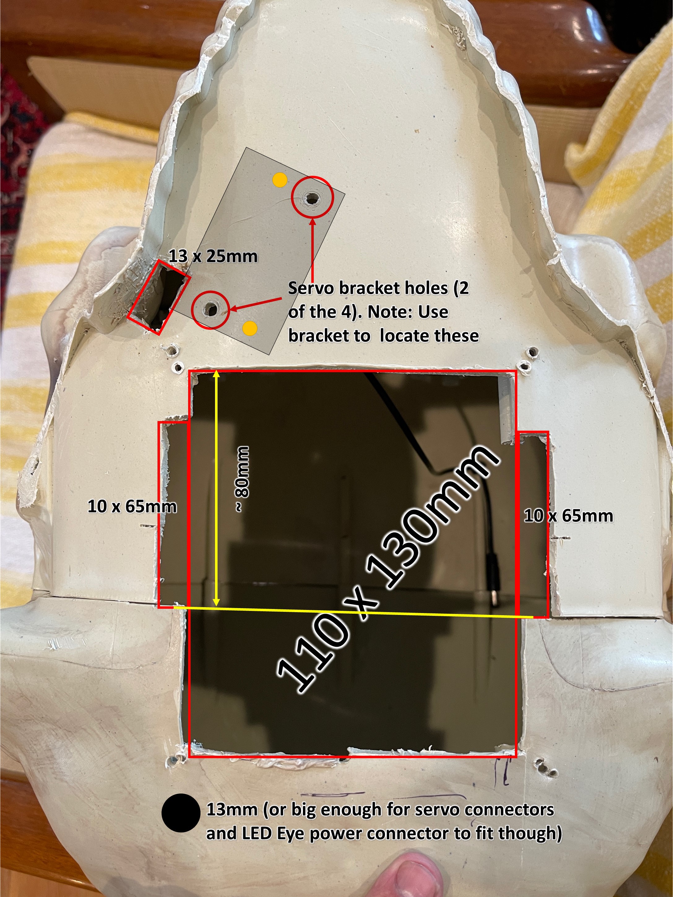
11Cutting the Skull (Do this at your own risk!!!!)
Main opening:
- The opening is approx 110mm x 130mm. Extend the middle of sides a bit (as shown) to make room for the assembly to fit in easily and not interfere with shoulder bolts.
Jaw Servo:
- Place the Servo into its servo bracket and line it up so the linkage comes out right behind the last bottom tooth. Mark where the screw holes need to be drilled.
NOTE: You will need to remove the plastic of the skull's screw holder on the underside near the jaw servo as it will interfere.
![]()
-
12Cutting the Jaw (Do this at your own risk!!!!)
- Follow the line between the teeth, then straight back after the teeth until you get to the shaded area, then try to cut as close to the main skull as possible.
![]()
-
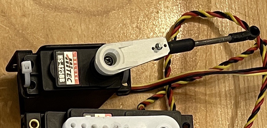
13Assembling the Jaw Servo
Didn't take any great pictures of the jaw servo, but here it is.
- I used a slightly different servo horn than what comes with the servo but using the outside hole on the stock one should work just as well.
The linkage was made up of parts I had laying around. The threaded rod I believe is 4-40 and if you look into 4-40 ball joints you will find them.
![]()
![]()
-
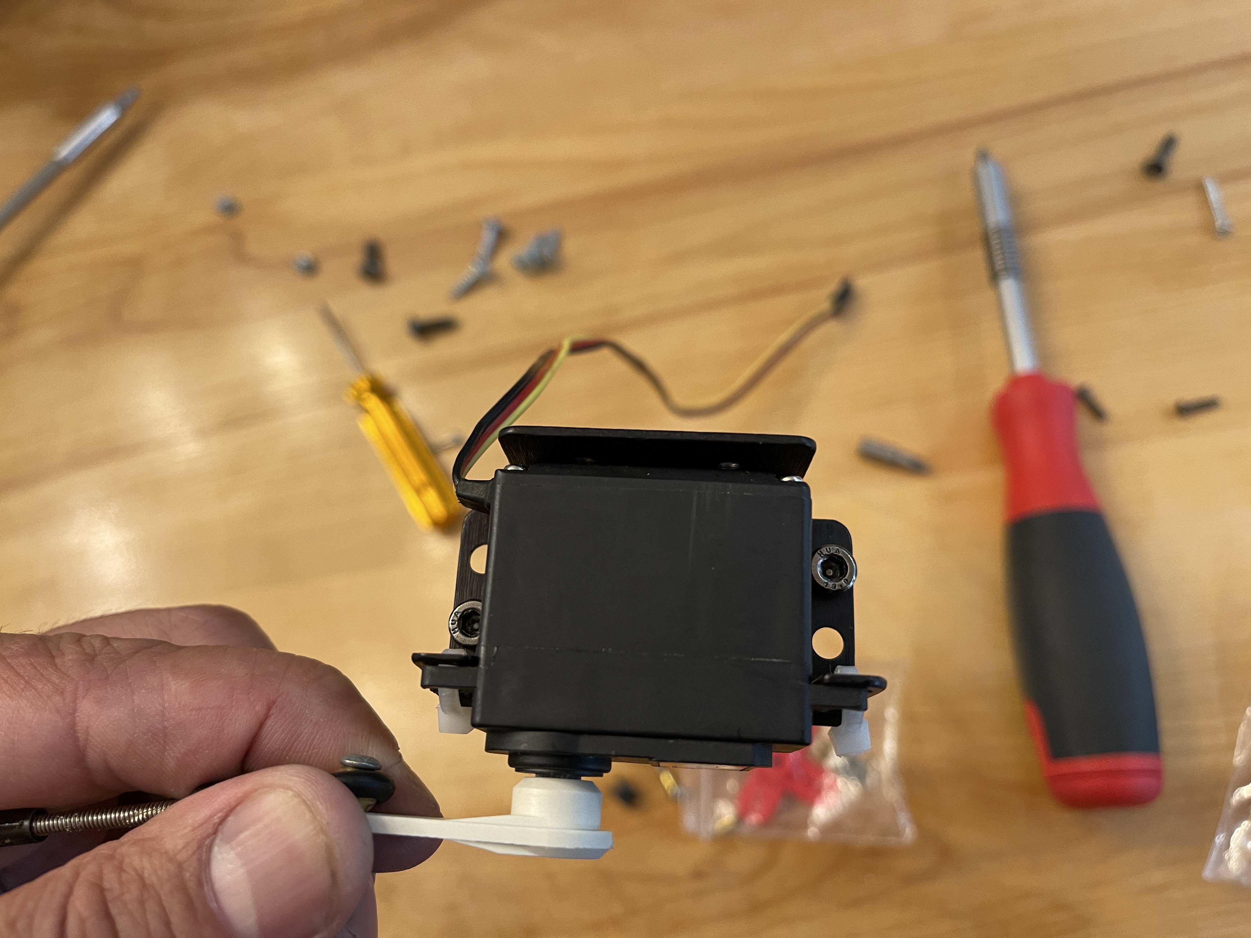
14Installing the Jaw Servo
- Install the servo inside of the skull with the servo horn and linkage positioned towards the opening by the jaw. Note: you may need to remove material around the area of the servo inside of the skull to give it a flat spot to sit.
Note: If using only 2 of 4 holes as I did, these are the screws below show which holes to use.
![]()
![]()
-
15Jaw Servo / Eye Wire routing
- It's recommended to use some type of wire clip to keep the wires from the jaw servo and skull eyes out of the way of the moving parts.
![]()
-
16Testing the 3-Axis Module
If you haven't already, this is the time to test the 3-Axis module before installing it.
- Attach it to the skeleton's neck, connect all your servos and make sure:
- That you can control each one
- There is no binding
- Nothing is loose
- Servo horns are centered properly
Note: Once it's in the skull, you will need to remove it to make adjustments.
![]()
- Attach it to the skeleton's neck, connect all your servos and make sure:
-
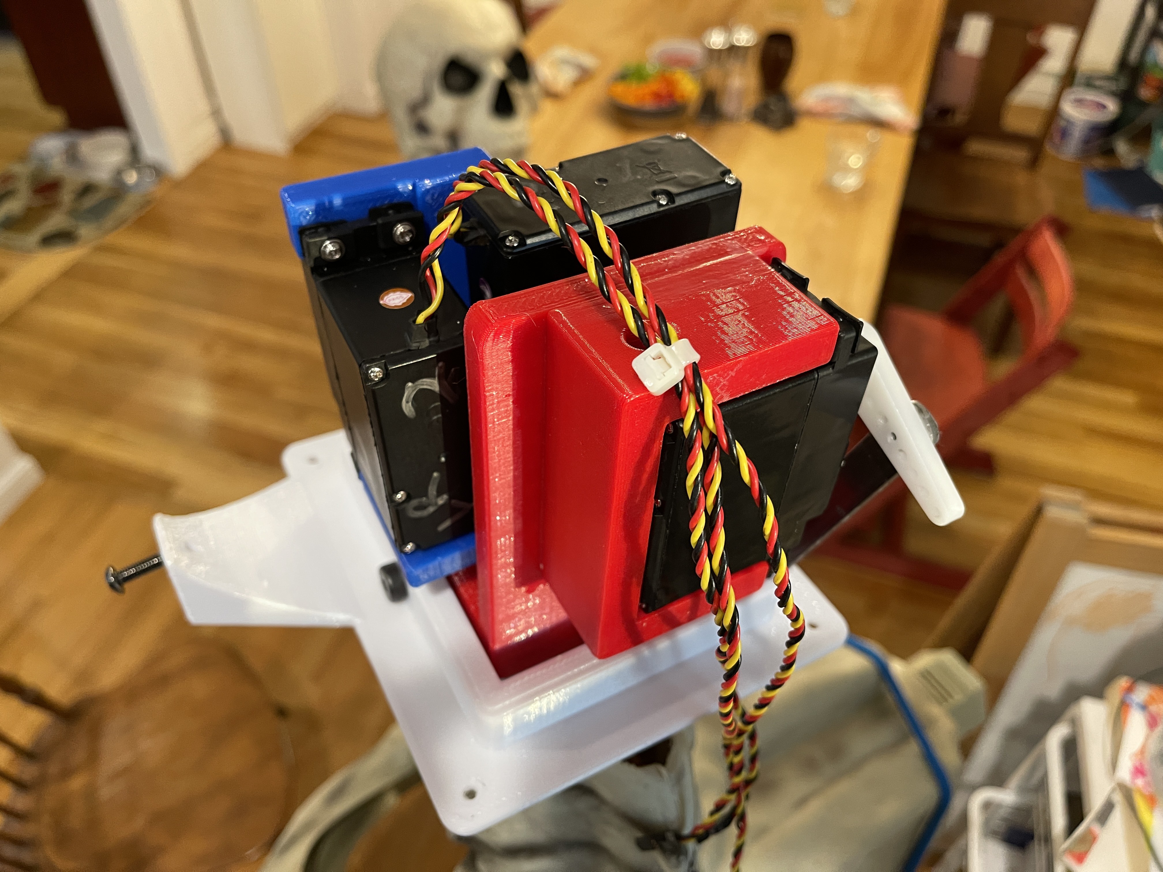
17Wire Routing
- Use a zip-tie to bundle the wires together near the back of the module (near the output of the nod servo wires).
- Making very sure that you have full motion without any strain on any of the wires.
![]()
- Use a zip-tie to bundle the wires together near the back of the module (near the output of the nod servo wires).
-
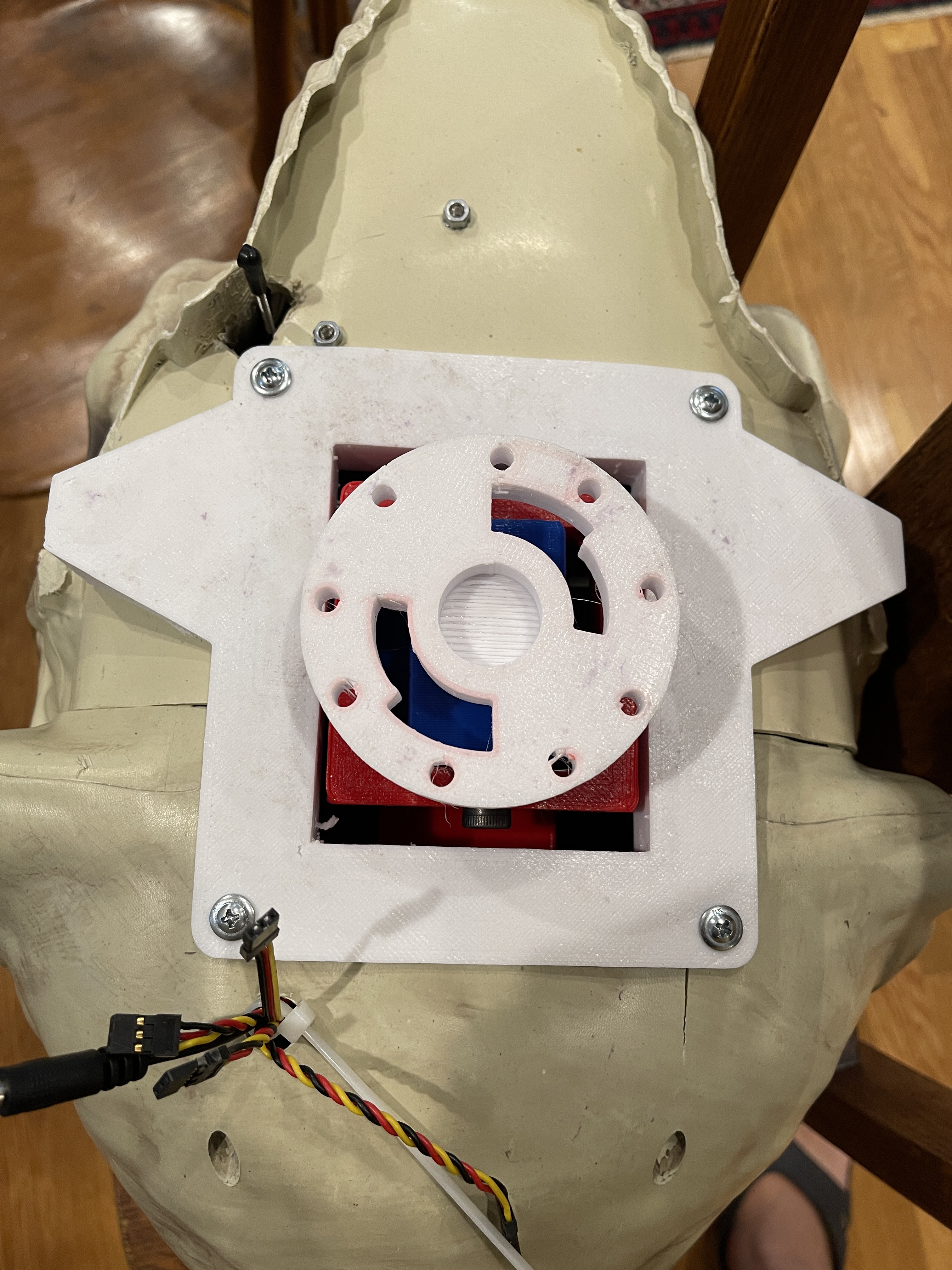
18Inserting the 3-Axis Module
- Make sure the wings (for the jaw) are facing forward and with a small bit of effort the module should slide right in. Be sure to stick the servo wires and eye power out the hole in the back.
- Before screwing in the plate, be sure that you can move the skull around by hand and no wires are being caught or anything is binding.
- Use 4 truss head screws (or similar) to secure the module. The plastic is fairly thick, but don't over-tighten or you will strip the plastic.
- I added a zip-tie on the output of the wires (not tight) to stop them from accidentally retreating back into the skull.
![]()
- Make sure the wings (for the jaw) are facing forward and with a small bit of effort the module should slide right in. Be sure to stick the servo wires and eye power out the hole in the back.
-
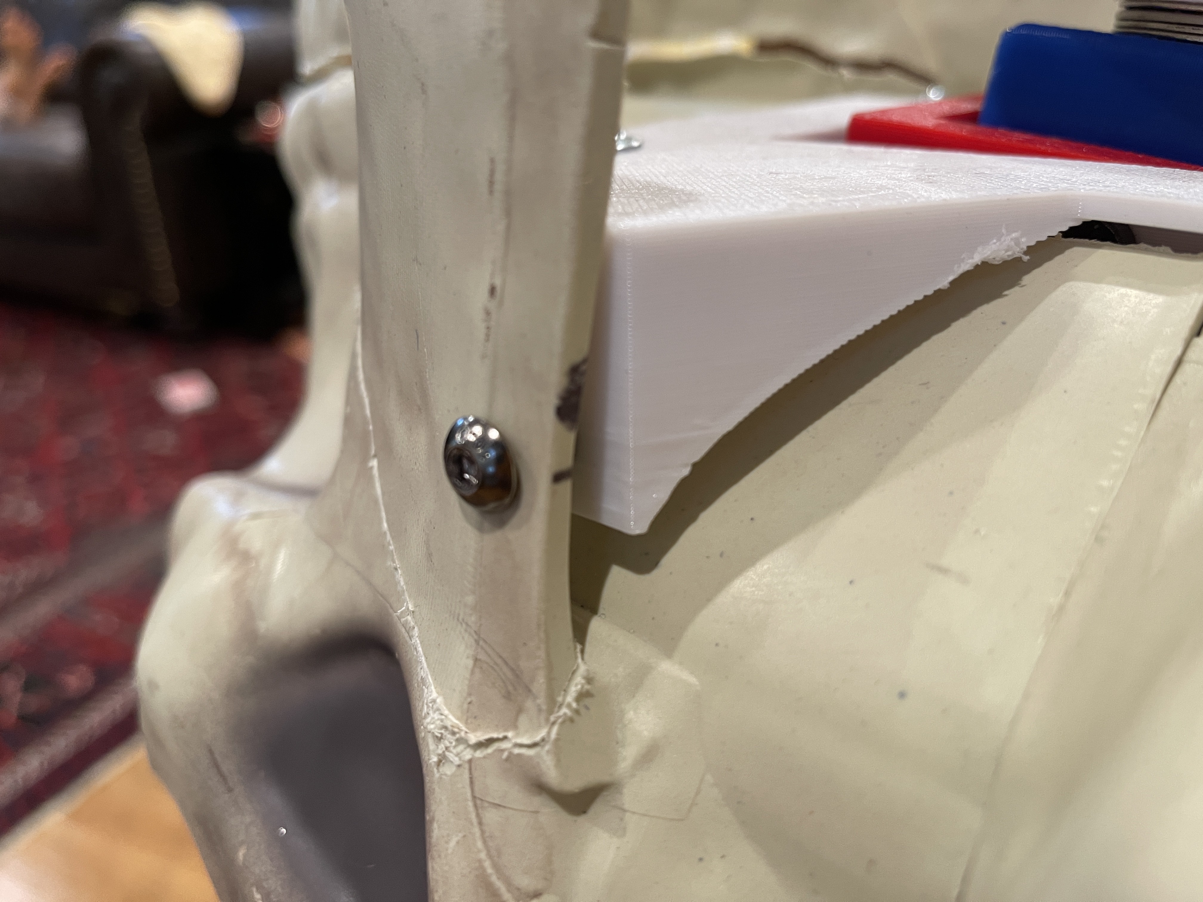
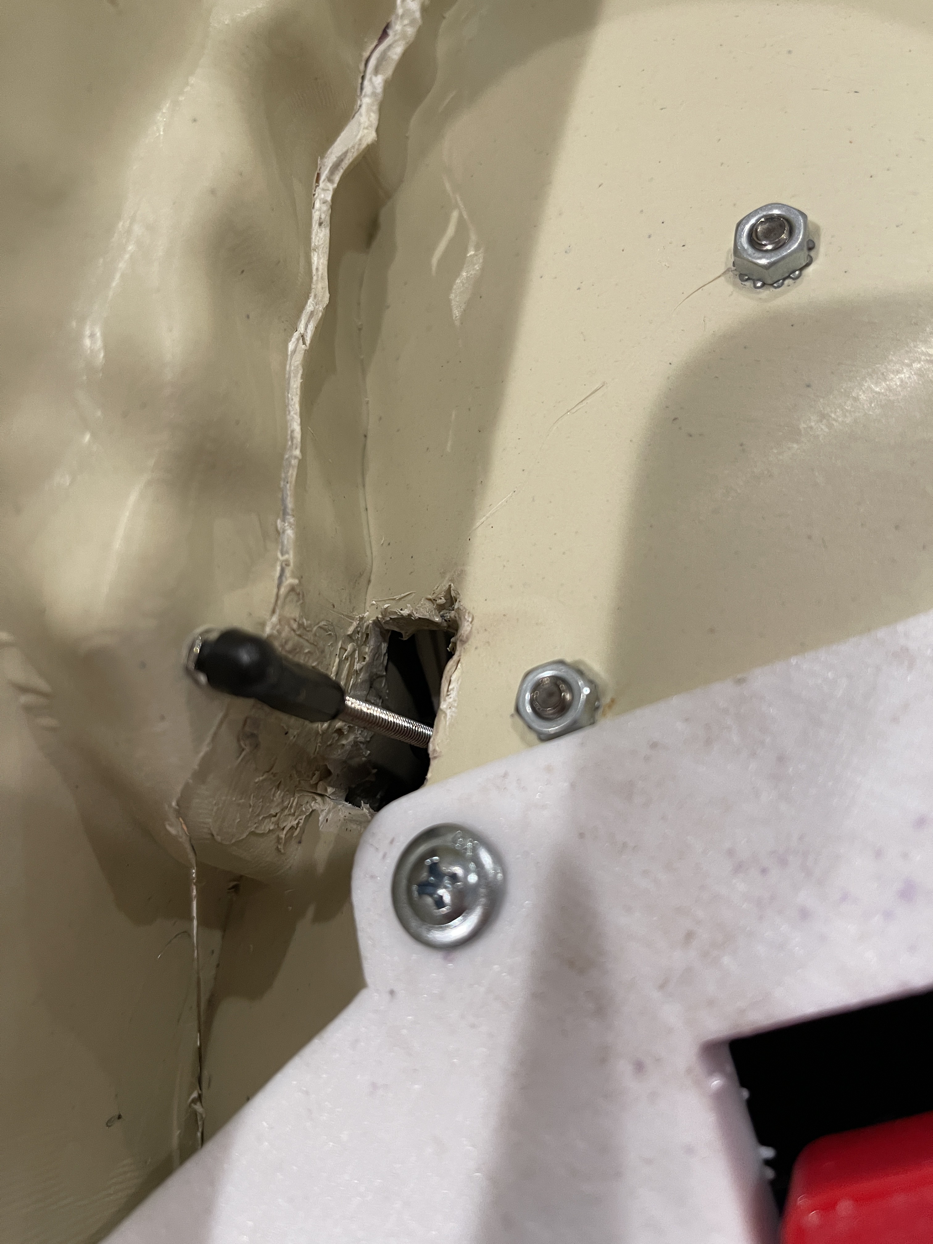
19Finding the Jaw Pivot Points
- With the skull upside down, place the jaw back in place.
- With a pen, make a mark where the screw hole should be drilled.
- Start by making a tiny hole where you think the hole should be and sticking a small wire through to see if you need to make an adjustment to where to drill the final hole.
- You will be using M6 screws, so the hole should be slightly bigger than screw but not lose.
- Screw in the M6 screws but not all the way, just to the point where the jaw lines up correctly.
- I'm assuming no two skulls are the same so I left room between the module and the jaw as things weren't very centered on my skull.
Note: Depending on how the jaw was cut, you may need to remove some material from the jaw if it scrapes against the skull while operating.
![]()
![]()
-
20Installing the Ball End into the Jaw
- Depending on the type of linkage you are using for the jaw, you will need to make a small hole near the back of the teeth for the linkage to attach.
- From here, test and adjust the linkage for the jaw to make sure you can close the jaw completely and open it a sufficient amount (remember, it doesn't need to open that far to be effective).
Note: I also ended up removing a small amount of plastic from the jaw and skull to allow the teeth to fully come together, not much but test and get it to where you are happy.
Note: The jaw isn't completely stiff so the gap between the teeth on the side without the servo linkage will be very slightly bigger.
![]()
![]()
3-Axis Skull Mod for 12ft Skeleton
The 12ft skeleton (Skelly) from Home Depot is an impressive decoration, but needs an extra kick to make it truly incredible!!!


Discussions
Become a Hackaday.io Member
Create an account to leave a comment. Already have an account? Log In.
Hi Justin, I used a Pololu Micro Maestro 6-Channel USB Servo Controller attached to a tiny PC. However, take a look at https://github.com/phatwila/skelly-animatronics which uses a Arduino board,
Are you sure? yes | no
could you by chance provide the controller board specs or board that you are using to drive this project?
Are you sure? yes | no
Hi Brent, that isn't covered here because there is a lot of information out there about servo based animatronics. You can start by looking at Cat's Menagerie, she covers the basics really well. https://www.youtube.com/channel/UCx1eztFY-gj_xPZ5vICyo9Q
Are you sure? yes | no
Wait, I don't see anything about the device to control everything, or how to setup the animations?
Are you sure? yes | no