David H Haffner Sr
-
Updated Concept Design For The DAV5 V3.01 Raman 3D Printable Spectrometer
06/21/2017 at 13:00 • 0 commentsI am completely redesigning my project out of necessity, the new triple turret grating motor addition demands it, and will facilitate a far superior performance factor. The 8 bit CCD detector may sound slower but indeed will be compensated with superior optical focal equipment.
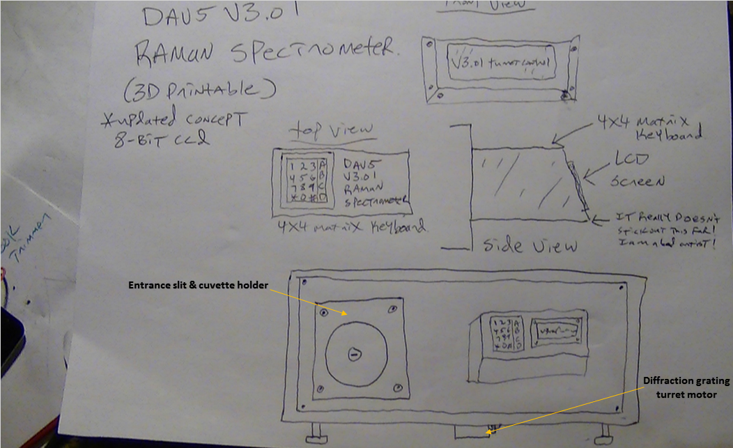
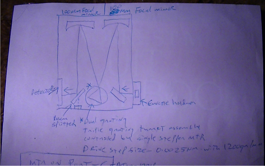
I still have not solved the 16 bit circuit problem and I'm just not going to mess with it any longer, so I am building the 8 bit right now. I am presenting my hand drawn sketch (not the best,) but it illustrates the concept well I think.
![]() I will be using a 4x4 matrix keypad alongside a 20 x 4 (yellow display,) 12c LCD. This will not only control the triple turret stepper motor but will be interfaced with the CCD data capture software (I am getting a little better at C/C++ programming now, so I am feeling more confident.)
I will be using a 4x4 matrix keypad alongside a 20 x 4 (yellow display,) 12c LCD. This will not only control the triple turret stepper motor but will be interfaced with the CCD data capture software (I am getting a little better at C/C++ programming now, so I am feeling more confident.) I hope those that read this post all the way through ( and not just "skim" the header,) will appreciate the simplicity that I have incorporated into the firmware for the turret control, because there are no external lib's needed other than the one for the LCD, and the stepper MTR control is stripped down to it's simplest functions, why? because what I found was, the most efficient method for using the controls that people have the most trouble with i.e,. Start/Stop CW/CCW Debouncing button controls ect.,
I have no debouncing code withing the control program because I have it in the hardware and it works with the momentary switches I use, besides, I tested 3 other prototype programs utilizing debouncing with PWM and all 3 failed, my guess perhaps too many "if" and "else" statements and not enough processing power in the Mega 2560 to handle the load (just my guess.)
When I stripped it all down to a basic framework and controlled the coils directly with a delay function everything sprang to life the way I imagined it. So if it ain't broke, I ain't gonna fix it!
Also I could not control the stepper MTR in the manner I wished using any type of stepper lib or with any type of PWM frequency manipulation, so instead of trying to re-invent the wheel, I just made everything simple :)
I hope I have explained my new concept enough for a clear understanding for what I am trying to accomplish, if not, please feel to discuss it with me constructive criticism is always a good thing and more people should engage in it. Your not going to hurt my feelings...Really :)
So please check out the video I posted the other day demonstrating the turret control program and it's new functions Updated...UniPolar Stepper Motor Controller Optimized
-
Updated...UniPolar Stepper Motor Controller Optimized
06/18/2017 at 10:09 • 4 commentsUpdated 6/26/17 1:58:PM
I updated the code significantly, I added " lcd.setCursor(12, 2); lcd.print(i--);" to the lines of code that control the motor coils so the current shaft position can be seen on the LCD display,and incorporated a pin int sensorVal[] = { digitalRead [2][3] };//SW1 pin2 & SW2 pin3
This will illuminat LED's #10(W) and LED #12(bl) to indicate that the switches
on HIGH. These values are then displayed on the LCD menu on line 3 as a monitor
of the switches values.
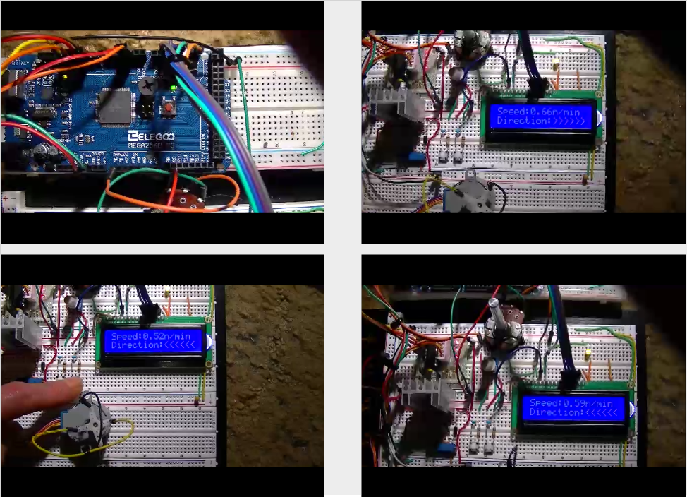
Note: You can see on the LCD screen that CW & CCW do not change, this is because the speed is way too high and the LCD cannot capture the characters fast enough...I think? Everything works fine when it runs at normal speed.
Here is my code as it stands right now;
#include <LiquidCrystal_I2C.h>
#include <Wire.h>
/* Program 1 REV B
Updated 6/26/2017 @ 1:48:PM
Code concept and project design by David H Haffner Sr.
Stepper program for the 28YBJ-48 (stepper MTR) and ULN2003 driver
This particular stepper motor is 5.625 degrees per step
/64
This is in the public domain.
Compiled size 6196 bytes.
*/
#define yellow 7 // M1
#define orange 5 // M2
#define brown 6 // M3
#define blue 4 // M4
#define CW 2 //Sw1 in schematic
#define CCW 3 //Sw2 in schematic
unsigned long int val = (analogRead('...') / 4 + 10);
LiquidCrystal_I2C lcd(0x3F, 2, 1, 0, 4, 5, 6, 7, 3, POSITIVE); // Set the LCD I2C address
void setup() {
pinMode(10, OUTPUT);// this is the LED pin10
pinMode(12, OUTPUT);// this is for LED pin12
digitalWrite(CW, 1); // pull up on
digitalWrite(CCW, 1); // pull up on
pinMode(blue, OUTPUT);
pinMode(brown, OUTPUT);
pinMode(orange, OUTPUT);
pinMode(yellow, OUTPUT);
// all coils off
digitalWrite(blue, 0);
digitalWrite(brown, 0);
digitalWrite(orange, 0);
digitalWrite(yellow, 0);
lcd.begin(20, 4); // initialize the lcd for 20 chars 4 lines, turn on backlight
// ------- Quick 3 blinks of backlight -------------
for (int i = 0; i < 3; i++)
{
lcd.backlight();
delay(250);
lcd.noBacklight();
delay(250);
}
lcd.backlight(); // finish with backlight on
// set up the LCD's number of columns and rows:
lcd.begin(20, 4);
// Print a message to the LCD.
lcd.print("AN/MAP:");
lcd.setCursor(12, 0);
lcd.print("0-1023");
lcd.setCursor(0, 1);
lcd.print("Direction:");//CCW or CC
lcd.setCursor(0, 3);
lcd.print("V3.01 Turret Control");//4th line for version display
lcd.setCursor(0, 2);
lcd.print("CurrentPos:");
Serial.begin(115200);
}
void loop() {
if (!digitalRead(CW)) {
forward(10);//rpm
all_coils_off();
}
if (!digitalRead(CCW)) {
reverse(10);//rpm
all_coils_off();
}
//read the pushbutton value into a variable
int sensorVal_1 = digitalRead(CW);//SW pin
//print out the value of the pushbutton
Serial.println(sensorVal_1);
// Keep in mind the pullup means the pushbutton's
// logic is inverted. It goes HIGH when it's open,
// and LOW when it's pressed. Turn on pin 10 when the
// button's pressed, and off when it's not:
if (sensorVal_1 == HIGH) {
digitalWrite(10, LOW);//LED pin
} else {
digitalWrite(10, HIGH);//LED pin
}
//read the pushbutton value into a variable
int sensorVal_2 = digitalRead(CCW);//SW pin
//print out the value of the pushbutton
Serial.println(sensorVal_2);
// Keep in mind the pullup means the pushbutton's
// logic is inverted. It goes HIGH when it's open,
// and LOW when it's pressed. Turn on pin 12 when the
// button's pressed, and off when it's not:
if (sensorVal_2 == HIGH) {
digitalWrite(12, LOW);//LED pin
} else {
digitalWrite(12, HIGH);//LED pin
}
} // end loop
void all_coils_off(void) {
digitalWrite(blue, 0);
digitalWrite(brown, 0);
digitalWrite(orange, 0);
digitalWrite(yellow, 0);
}
void reverse(int i) {
{
lcd.setCursor(10, 1);
lcd.print("<<CCW");
}
while (1) {
digitalWrite(blue, 1);
digitalWrite(brown, 0);
digitalWrite(orange, 1);
digitalWrite(yellow, 0);
delay(analogRead('...') / 4 + 10);
i--;
if (i < 1) break;
{
lcd.setCursor(12, 2);//print out the value of the pushbutton
lcd.print(i--);
}
digitalWrite(blue, 0);
digitalWrite(brown, 1);
digitalWrite(orange, 1);
digitalWrite(yellow, 0);
delay(analogRead('...') / 4 + 10);
i--;
if (i < 1) break;
{
lcd.setCursor(7, 0);
lcd.print(analogRead('...') / 4 + 10);
}
digitalWrite(blue, 0);
digitalWrite(brown, 1);
digitalWrite(orange, 0);
digitalWrite(yellow, 1);
delay(analogRead('...') / 4 + 10);
i--;
if (i < 1) break;
{
lcd.setCursor(12, 2);//print out the value of the pushbutton
lcd.print(i--);
}
digitalWrite(blue, 1);
digitalWrite(brown, 0);
digitalWrite(orange, 0);
digitalWrite(yellow, 1);
delay(analogRead('...') / 4 + 10);
i--;
if (i < 1) break;
{
lcd.setCursor(12, 2);//print out the value of the pushbutton
lcd.print(i--);
}
}
}
void forward(int i) {
{
lcd.setCursor(10, 1);
lcd.print("CW>>>");
}
while (1) {
digitalWrite(blue, 1);
digitalWrite(brown, 0);
digitalWrite(orange, 0);
digitalWrite(yellow, 1);
delay(analogRead('...') / 4 + 10);
i--;
if (i < 1) break;
{
lcd.setCursor(12, 2);//print out the value of the pushbutton
lcd.print(i--);
}
digitalWrite(blue, 0);
digitalWrite(brown, 1);
digitalWrite(orange, 0);
digitalWrite(yellow, 1);
delay(analogRead('...') / 4 + 10);
i--;
if (i < 1) break;
{
lcd.setCursor(12, 2);//print out the value of the pushbutton
lcd.print(i--);
}
digitalWrite(blue, 0);
digitalWrite(brown, 1);
digitalWrite(orange, 1);
digitalWrite(yellow, 0);
delay(analogRead('...') / 4 + 10);
i--;
if (i < 1) break;
{
lcd.setCursor(12, 2);//print out the value of the pushbutton
lcd.print(i--);
}
digitalWrite(blue, 1);
digitalWrite(brown, 0);
digitalWrite(orange, 1);
digitalWrite(yellow, 0);
delay(analogRead('...') / 4 + 10);
i--;
if (i < 1) break;
{
lcd.setCursor(12, 2);//print out the value of the pushbutton
lcd.print(i--);
}
}
}
stepper program for the 28YBJ-48 (stepper MTR) and ULN2003 driver
This particular stepper motor is 5.625 degrees per step
/64
Speed is controlled by a delay between each step.
The longer the delay the slower the rotation.
That delay value is obtained by reading the analog-to-digital
cover (A0 in this case/10K trimmer POT) which gives a value from 0 to 1023.
The value is divided by 4 and add 10 for a delay
in milliseconds:delay(analogRead(0)/4 +10)
For faster speeds change 10 to say 2.
This is calculated between every step to vary speed while stepping.
![]()
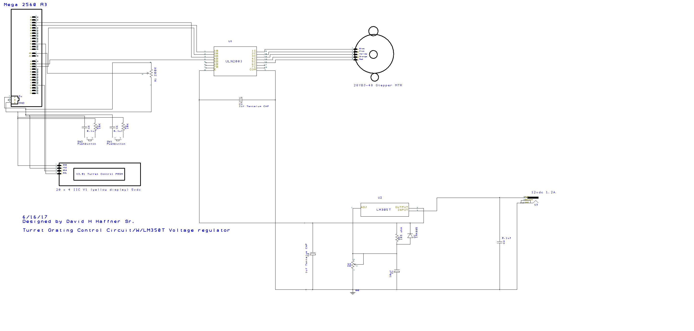
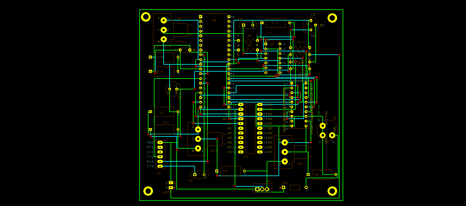
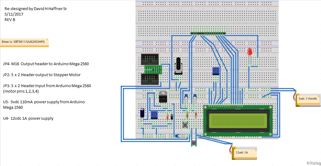
Here is the circuit schematic, I am using a new 20 x 4 LCD display (yellow background) I bought from YourDuino.com, on the schematic I have a 200K trimmer POT, I was experimenting with different values and realized quickly that the source will become to weak for the ADC (internally), resulting in errors, and I'm not going to mess around with buffers and signal conditioning circuits. (Just UR typical 0.1uf CAP(+ end) & 10K resistor to GND @ each button)
So I dropped it back to the typical 10K POT, works just fine.
Some highlights of my code are:
1) NO debouncing programs
2) NO external Stepper libraries
3) Minimal stress imposed on the processor (in my opinion a faster response)
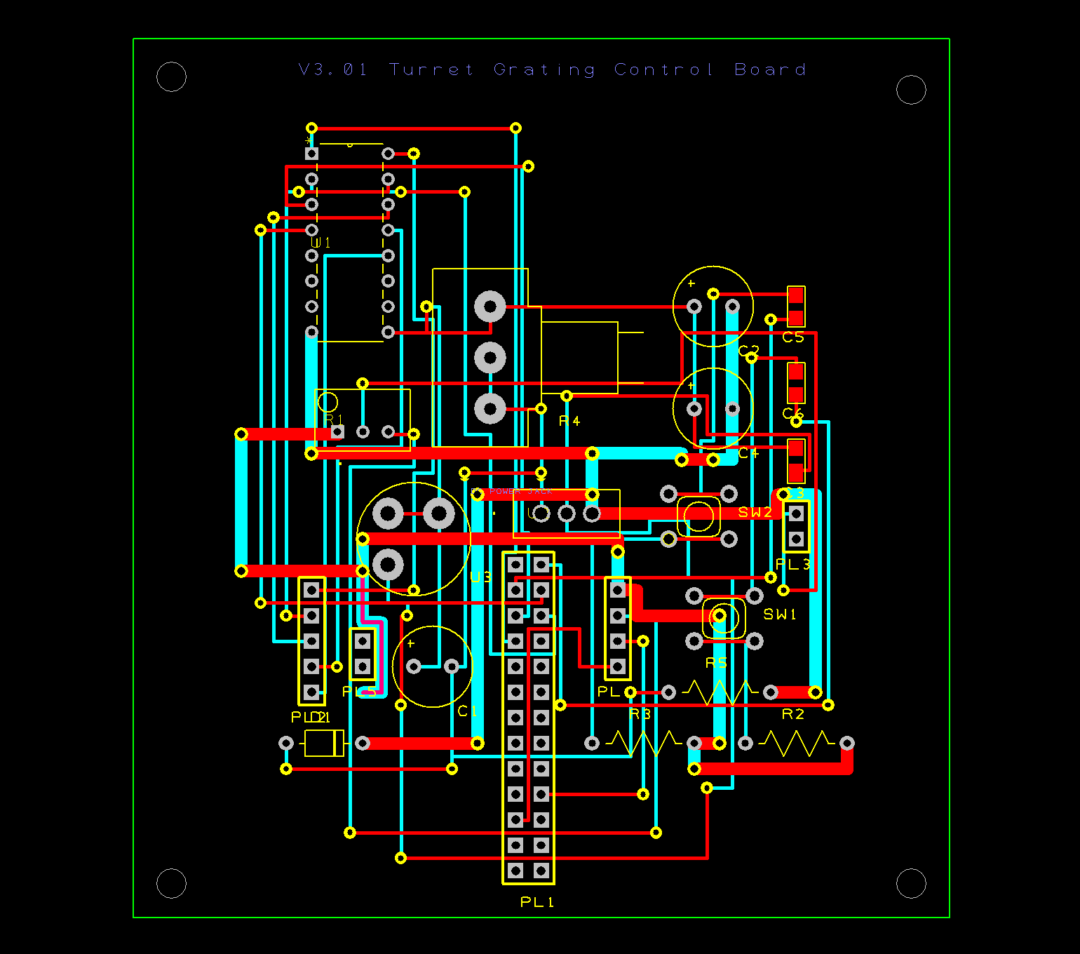
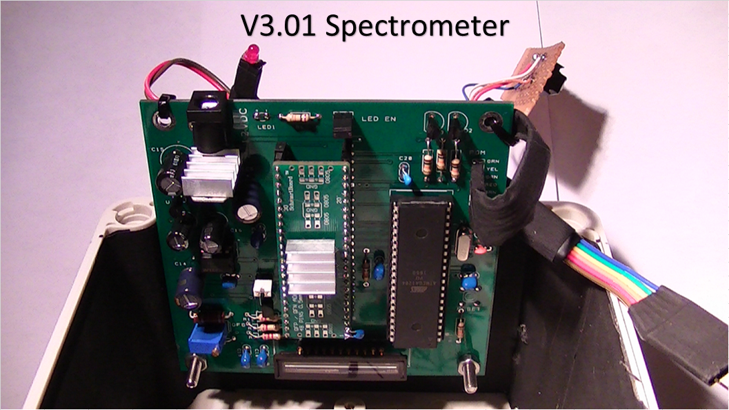
Below is the PCB circuit board, this is the easiest way to interface with the Mega 2560 R3
![]()
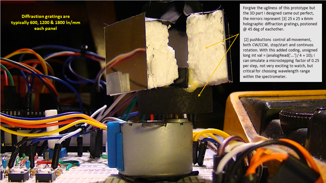
![]() Here is the prototype in the above picture
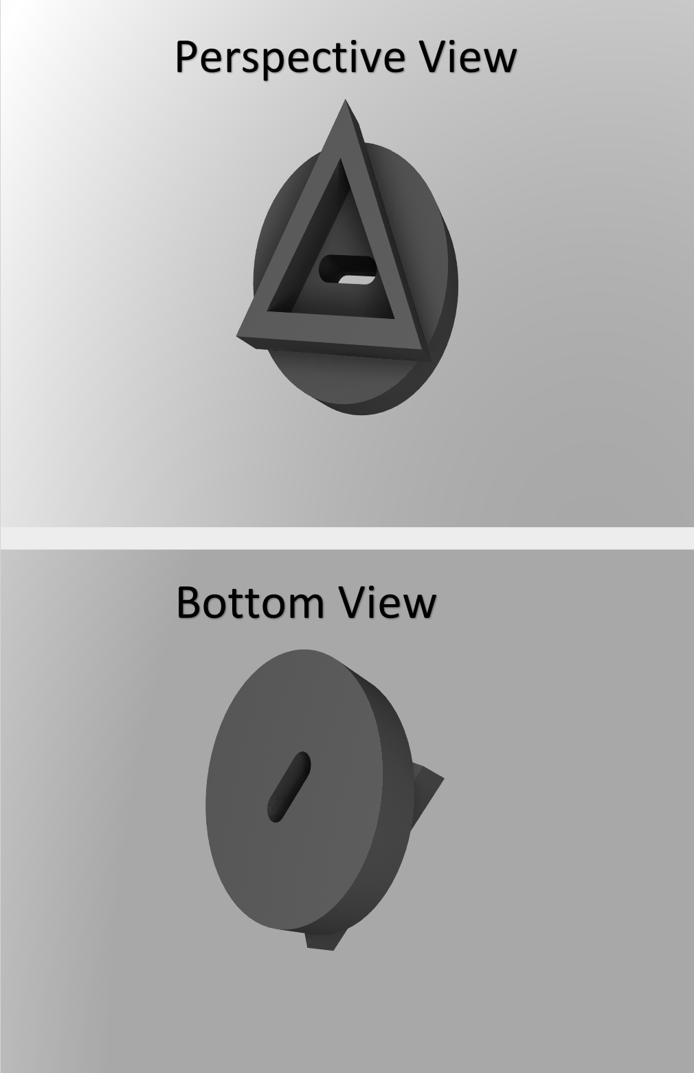
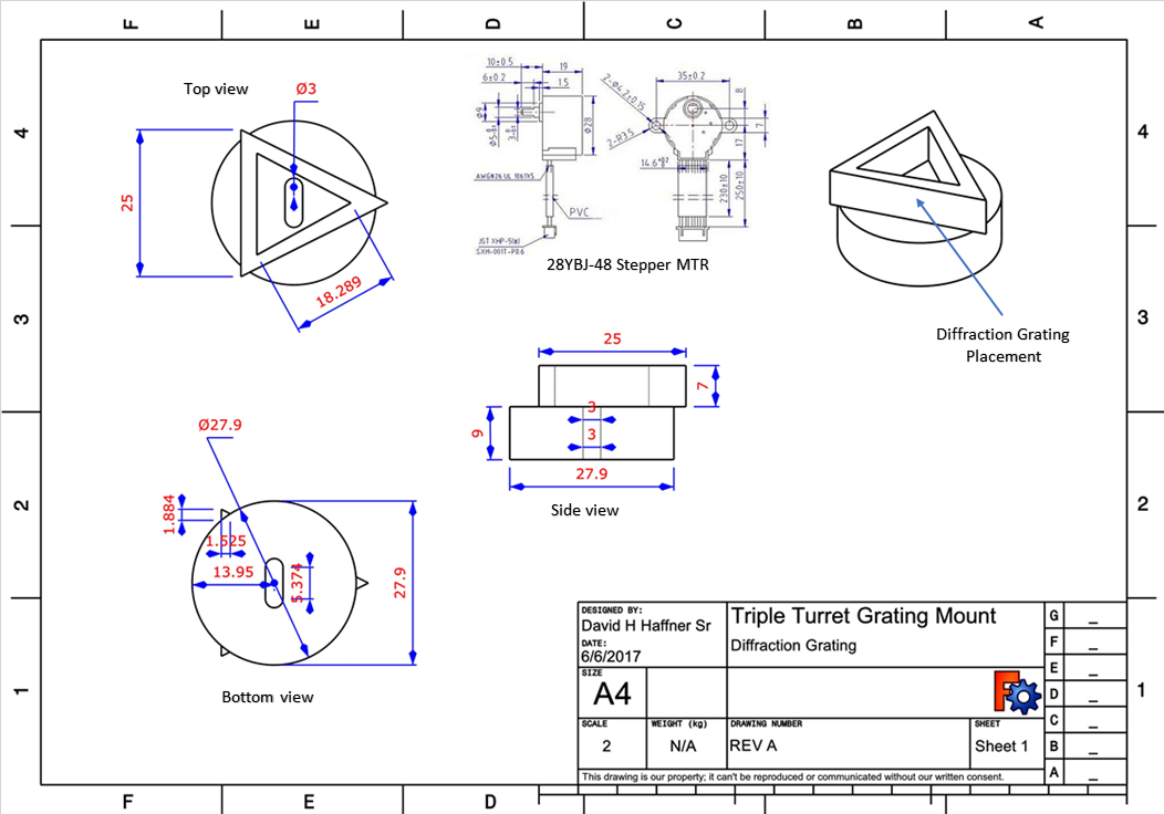
Here is the prototype in the above pictureI designed the turret mount on FreeCad 0.16, and had it 3d printed @ Sculpteo using POM (powdered nylon material) cost of this part; $15.67 US. not too bad :)
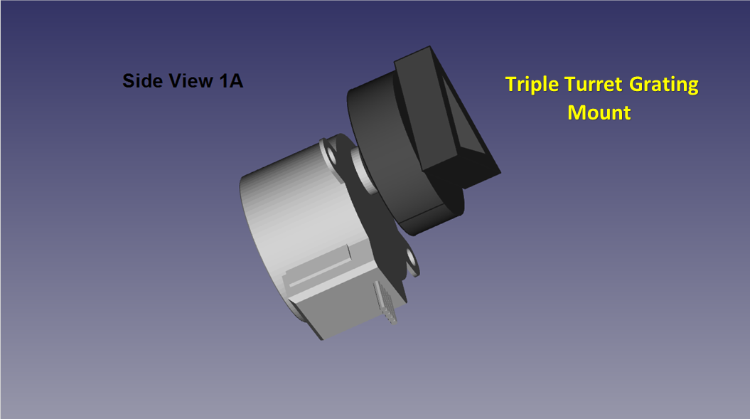
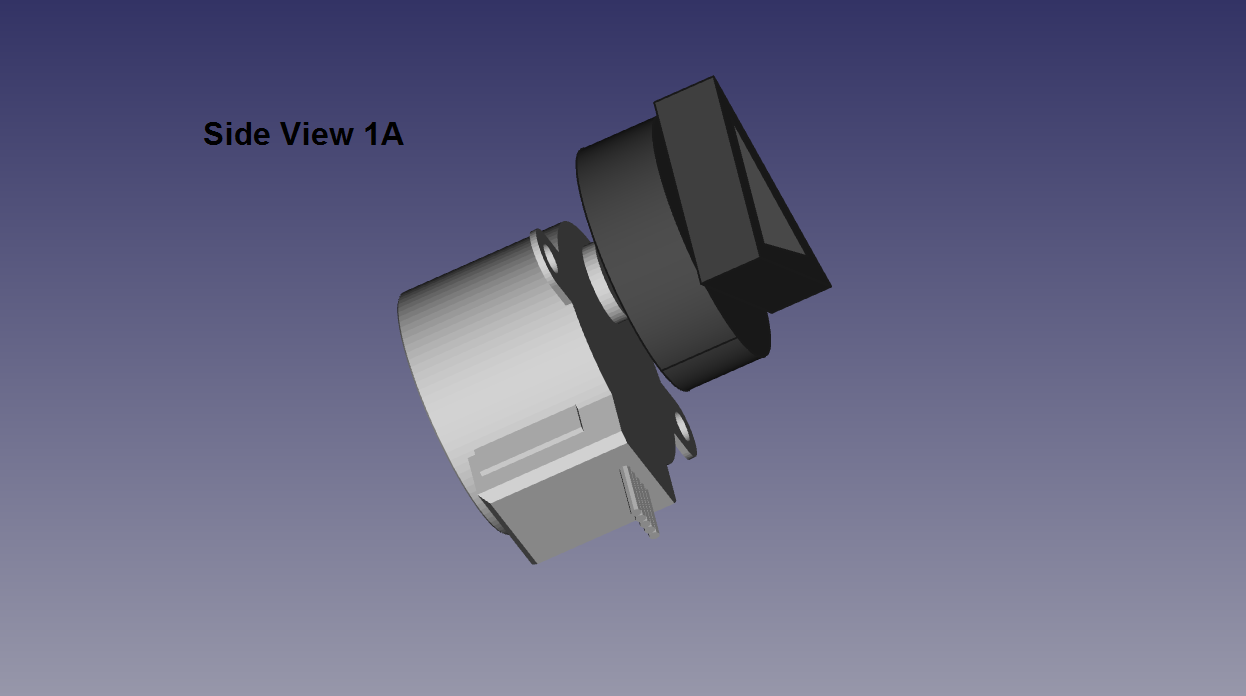
![]() A recap of the 28YBJ-48 Stepper Motor and the Triple Turret Grating Mount assembly
A recap of the 28YBJ-48 Stepper Motor and the Triple Turret Grating Mount assemblyFull project design and schematic files plus gerber files for the PCB can be found in the typical files location on my projects page here :)
-
Microstepping The 28YBJ-48 Stepper Motor
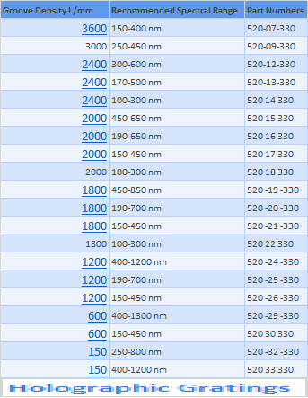
06/09/2017 at 10:44 • 0 commentsAdvantages of multi-grating turrets in spectrometers
Phase I
There are significant advantages of multi-grating turrets in spectrometers. Quite often it becomes necessary to select two or three gratings to achieve efficient light throughput over a broad spectral region. Turrets make grating changes an easy push-button or computer controlled operation, and also reduce the risk of handling the delicate gratings.
With this upgrade to the V3.01 Raman spectrometer, I’m bringing a level of functionality to this project that may be unprecedented. Imagine a piece of lab equipment costing under $1,600.00 having the same high precision and functionality as those costing ten’s of thousands more. How is this made possible?Through the innovations of 3D printing and the new type of techniques and materials that can be utilized.
In my designs, I use glass-filled Nylon for all my parts. Objects printed in glass-filled nylon are made from a mix of polyamide powder and glass beads. The surface of the material is white and slightly porous. Glass-filled Nylon is more durable and resistant than Polyamide 12. It gives you great freedom in your designs – allowing for both complex and inclosed volumes. The material is great for technical parts that need resistance and loads. The surface of glass-filled nylon is not as accurate as polyamide but it will fit the requirements of technical parts. Also it fits my budgetary needs.
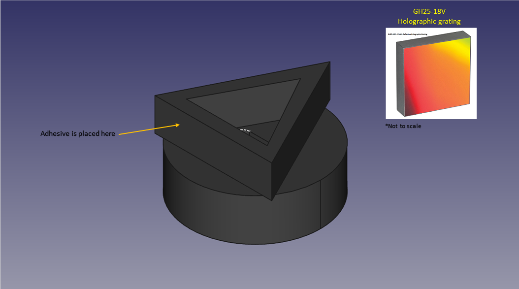
![]()
The rendering above is the grating mount
![]()
![]()
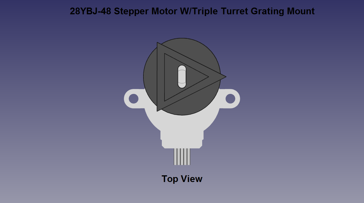
This panels above illustrate the fully assembled grating mount and 28YBJ-48 stepper motor![]()
![]()
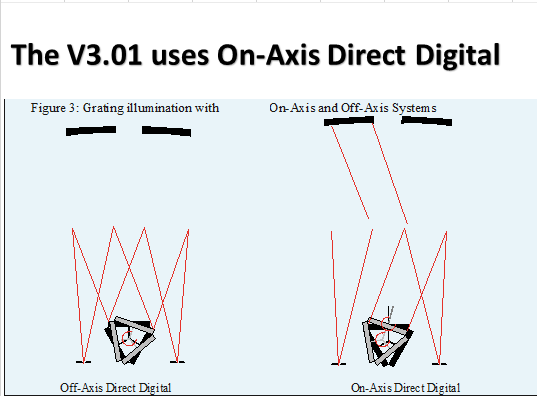
![]() Several studies have been done evaluating both off-axis and on-axis grating rotation techniques for spectral resolution and conclusions are that, careful alignment and focusing of the total system has a more dramatic impact on performance than the grating rotation technique chosen.
Several studies have been done evaluating both off-axis and on-axis grating rotation techniques for spectral resolution and conclusions are that, careful alignment and focusing of the total system has a more dramatic impact on performance than the grating rotation technique chosen.![]() The above figure illustrates both techniques, utilizing on and off axis grating rotation.
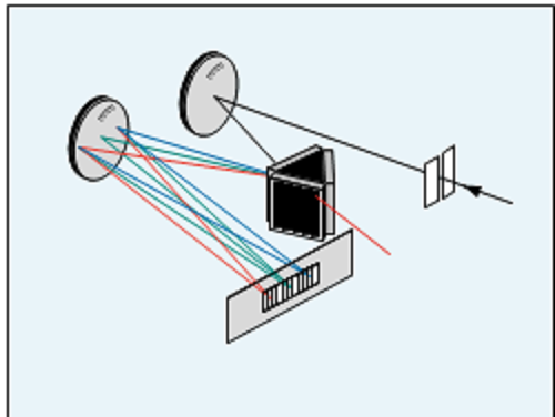
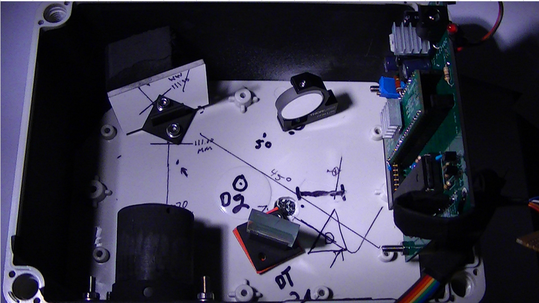
The above figure illustrates both techniques, utilizing on and off axis grating rotation.![]() This is the fully assembled system within the V3.01 Raman Spectrometer
This is the fully assembled system within the V3.01 Raman SpectrometerThis is the end of phase I, in phase II I will be determining several points;
- Operation: How easy is the system to set up and operate?
- Computer control: How easy is the instrument computer control?
-
PLX-DAQ Arduino and Excel in Windows 10/Atmega1284
05/30/2017 at 06:41 • 0 commentsUPDATE 5/30/2017 10:06:AM
I have just tested this program on my Atmega1284P Dev board and it works perfectly :)
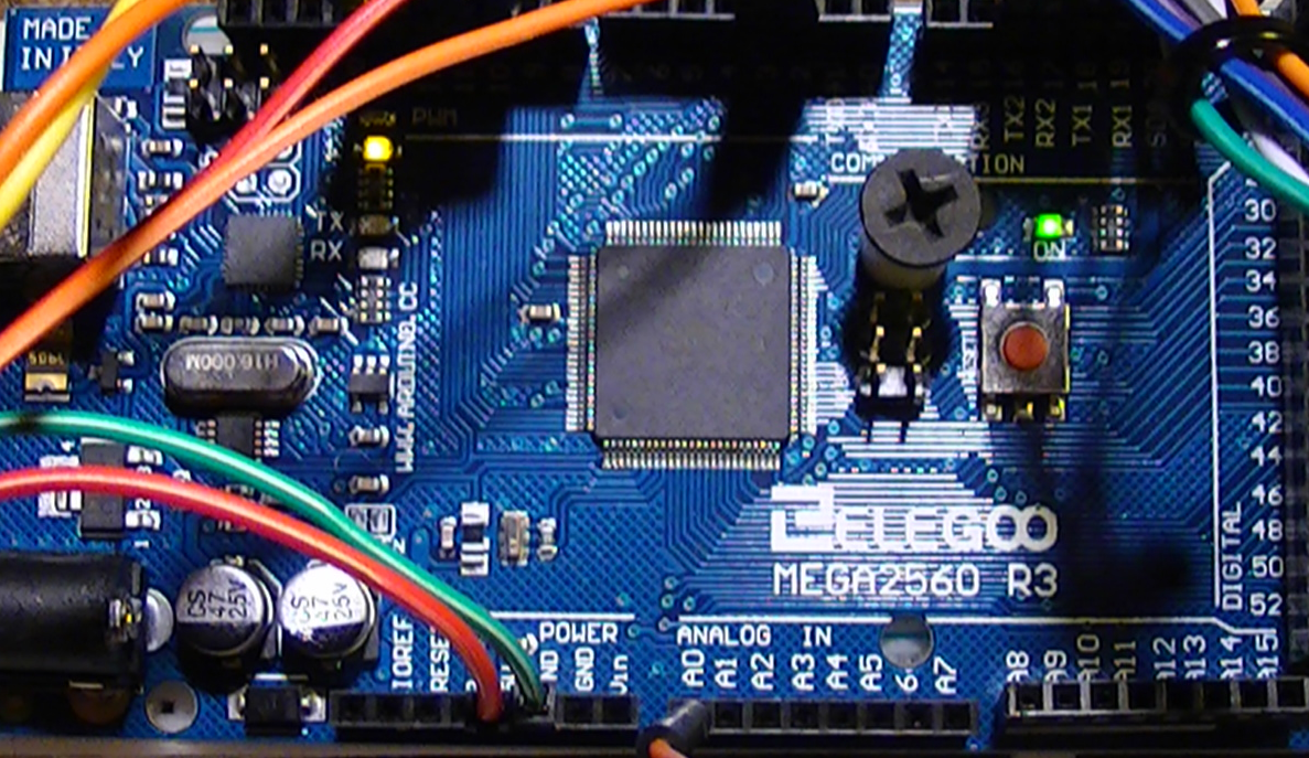
I have Excel 2016 and Windows 10, two powerful platforms in my humble opinion, well thanks to an individual named Net^Devil over at the Arduino forums, he has a very clever program that I think perhaps has in large part solved a problem for me.
I needed an alternative way of importing my CCD data directly into Excel, his program PLX-DAQ v2 does this and is completely open sourced. I have modified the sketch of the test program which makes it a lot more stable on the Excel data side (this may not be an issue for earlier versions of windows but is for windows 10).
![]()
![]()
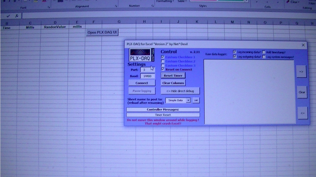
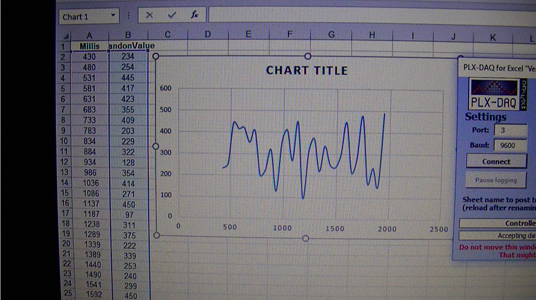
Here is the PLX GUI panel opened in Excel, on my Mega 2560 my com port is 3 and my baud rate is 14400 (right now any faster and excel stops working? don’t know yet)
The documentation is good and easy to set the program up.
![]()
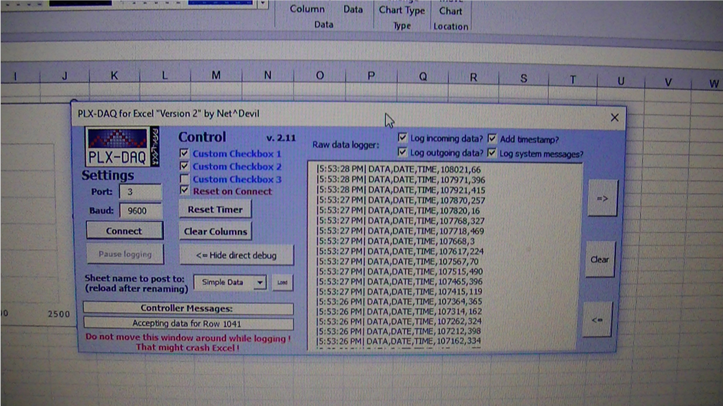
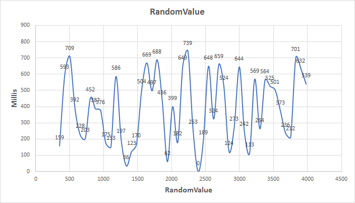
This is the random number generator program running
![]()
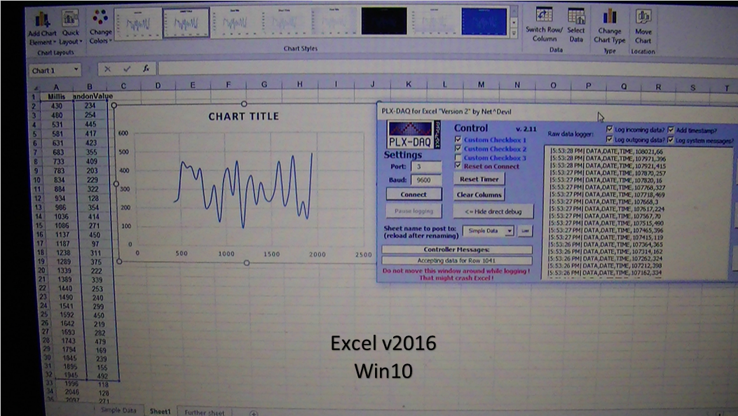
All data has been imported from the Atmega 2560 into Excel, you can see the data to your left in columns A and B.
![]()
You an see here in the zoomed in view, that it makes life a lot easier when manipulating data and constructing charts all in one shot
![]()
![]()
![]()
The top chart is the raw data, and the bottom chart is a zoomed in view of the data "call outs".
![]()
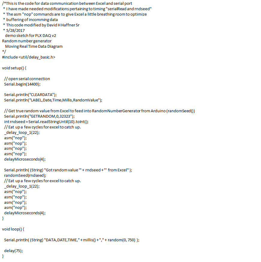
This is the test code for the random # generator for the Mega 2560, I’ve added the #include <util/delay_basic.h> lib, because I needed to incorporate a few delay functions to give Excel some time to catch it’s breath. Using the demo sketch by itself Excel, at least in Windows 10 will crash, so I increased millis() delay to at least (75) and added a couple of “do nothing” cycles, and it did the trick (but only at baud 14400).
Still all in all, this is very promising and I hope to modify it so it is adaptable to my Atmega1284P MCU…Any help out there would be greatly appreciated!
My project moves ever forward! :)
-
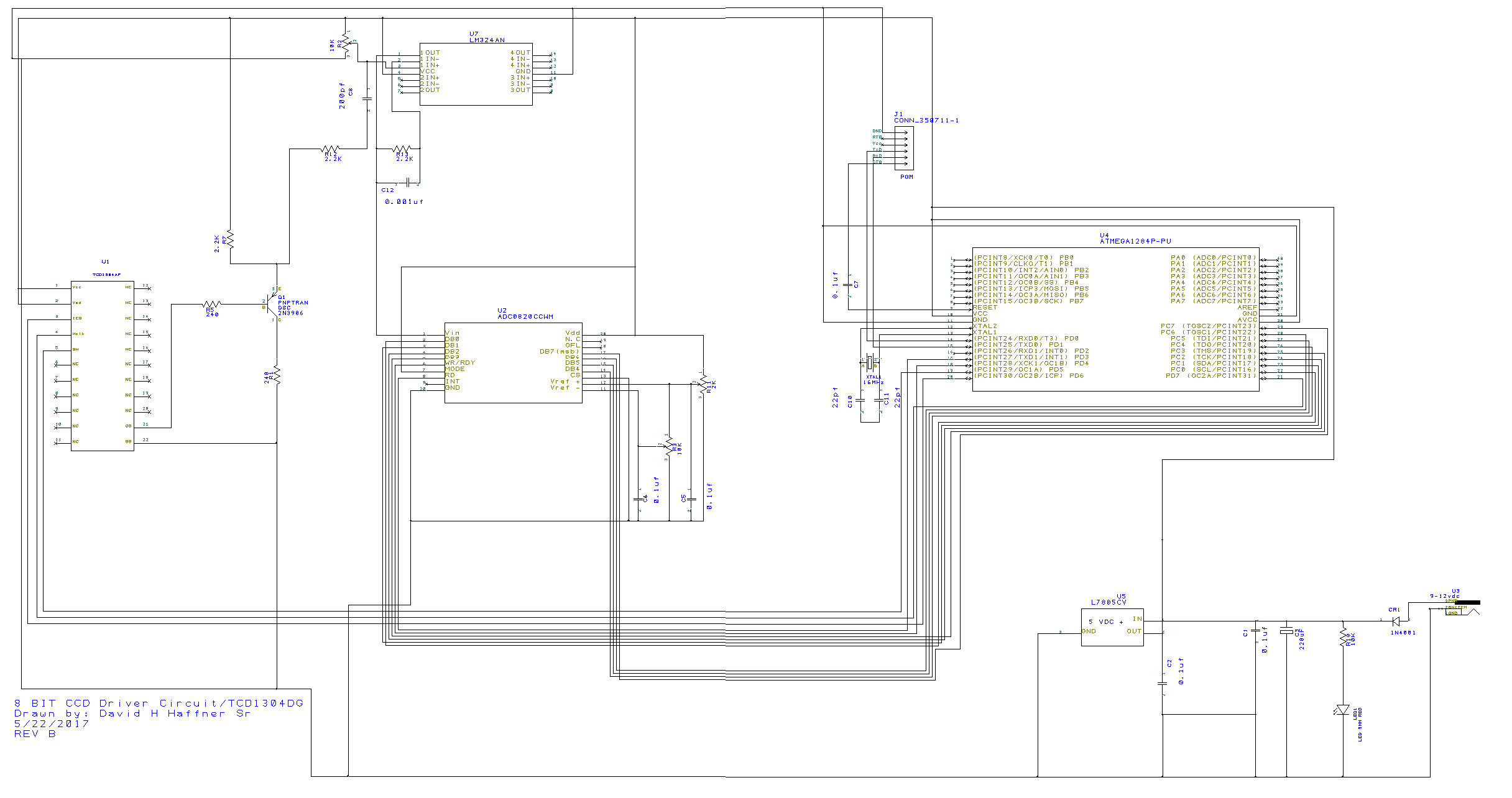
Fast 8 Bit CCD Driver Circuit REV B
05/26/2017 at 12:46 • 0 comments![]()
I had to put the 16 bit driver circuit on hold for right now, there is an over heating problem with the ADC that I cannot solve right now, I have 2 boards made up and both have the same issue.
So I have decided to go ahead and build the fast 8 bit drive instead because I already know that it works flawlessly, and can still read all 3648 pixels from the CCD, It reads 3694 pixels, but the first 30 and the last 16 are dark reference or dummy pixels and are discarded.
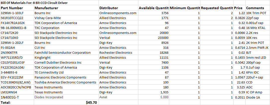
I have already drawn the schematic using Design Spark and will post the gerber files so you can order your own PCB and build it. I am including the BOM also.
![]()
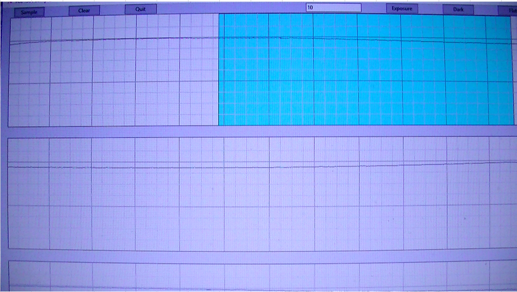
This next set of panels are from the 16 bit driver circuit![]()
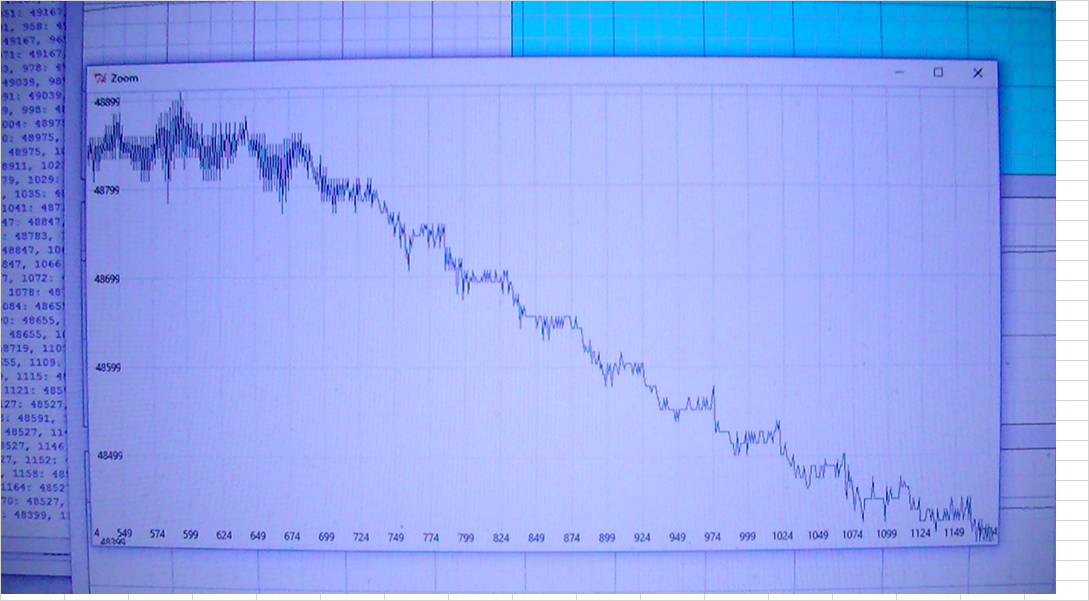
This was the tail end of a CFL lamp (2300K/13W) but the ADC starts to overheat and you can start to see the results on screen.![]()
Although the spectral image is inverted, this was the best initial capture of the CFL lamp, from left to right; the 2 most important calibration bands are the blue bands on the left, which should be at 432nm and to the right at the green band should be at 546nm this gives the best "fit," so to speak.![]()
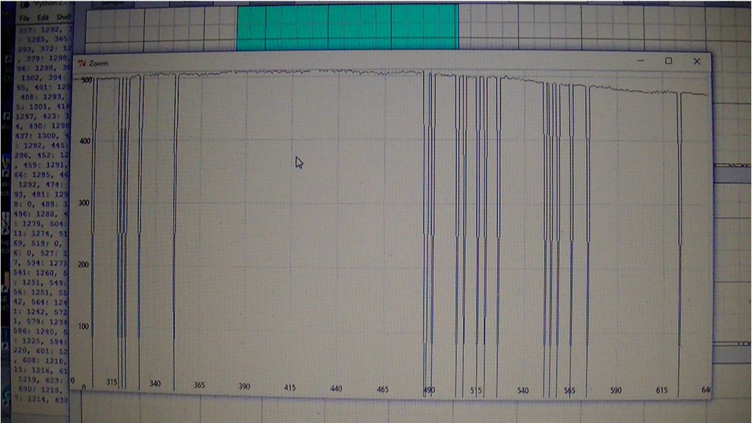
This was the first scan "dark counts."![]()
As I stated earlier, I'll still be working on this problem, but I need my project to start moving forward and it will with the 8 bit driver and still have very good resolution because of the optics and 1800 ln/mm holographic grating I am using and Raman edge pass filter, the only difference will be digitizing a frame will take 32ms instead of 16ms.
Other than that, there isn't too much of a real difference.
-
Atmega 2560 Triple Turret Stepper Motor Control Circuit Board
05/22/2017 at 07:52 • 2 commentsThis is REV B of my Mega 2560 stepper Motor control circuit driver control board, I had to fix the switches as they were not working properly, now they do since I debounced them, I am posting a YouTube video showing it's operation
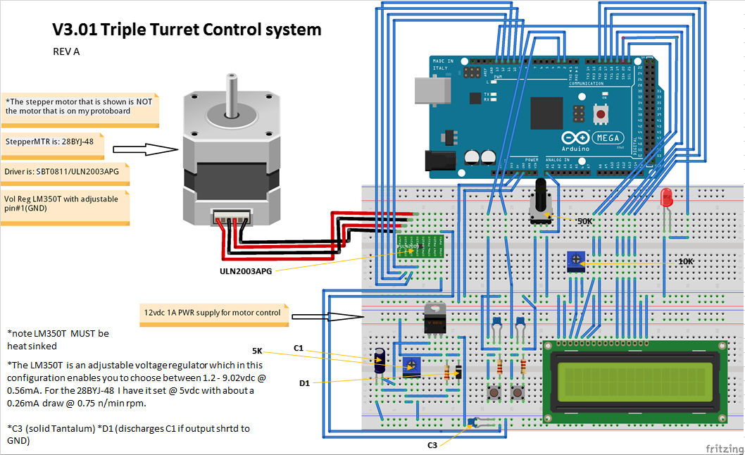
Below is the Arduino breadboard schematic showing the entire layout;
![]()
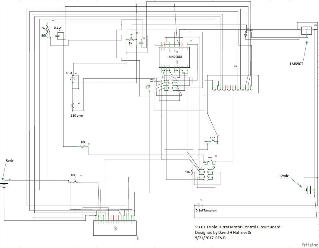
Next is the Fritzing schematic;
![]()
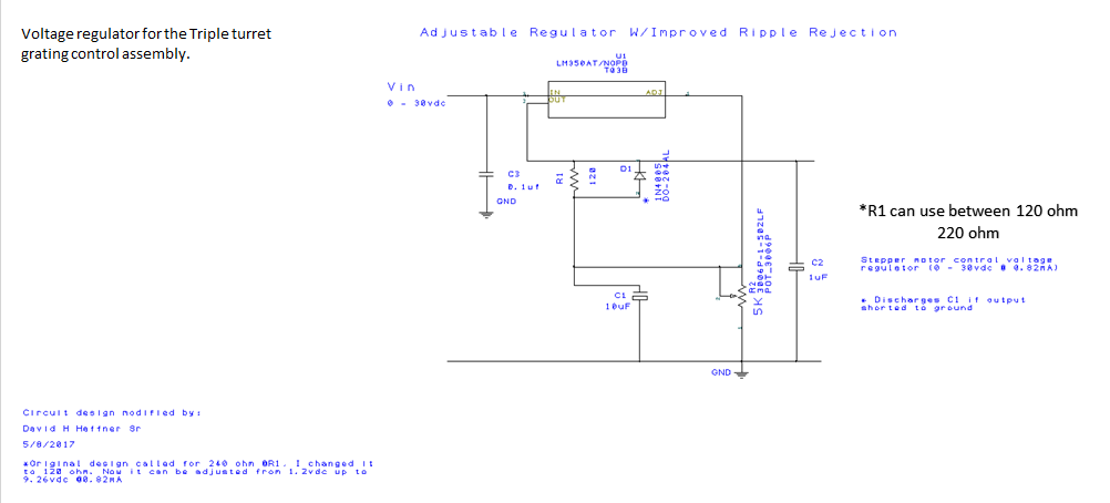
Here is the schematic for the LM350T voltage regulator;
![]()
Next is an Arduino barebones breadboard layout;
![]()
A 4 panel snapshot view;
![]()
-
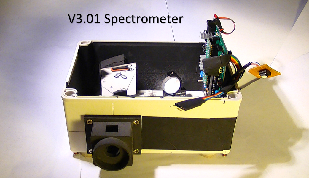
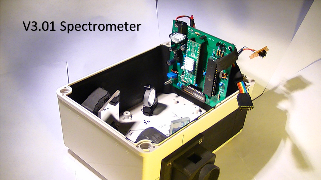
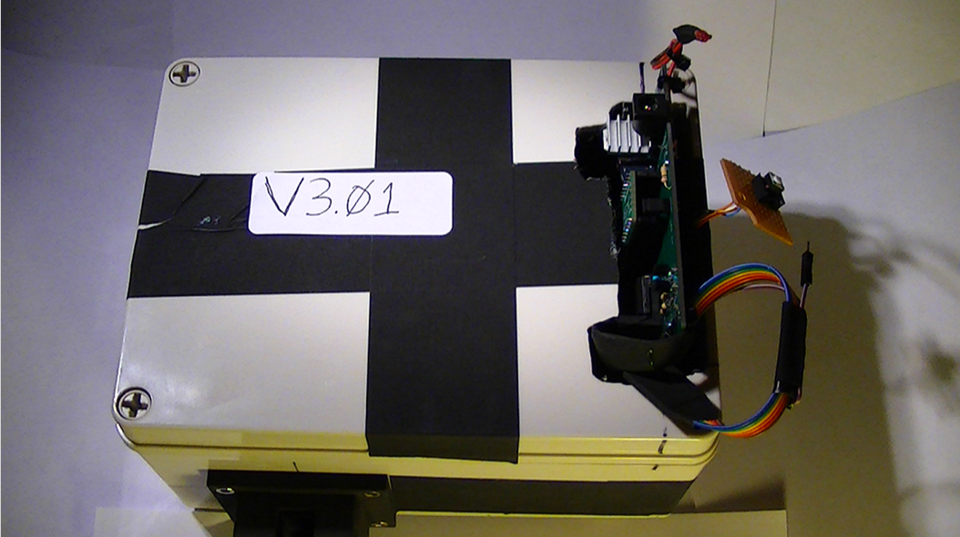
*Update* V3.01 Raman Spectrometer Prototype Redesign Works!
05/20/2017 at 10:26 • 0 commentsMy next post will be the data specs for the CCD driver circuit, yes, it works...Yippie! I had to place the circuit board back in my prototype testing platform for now, until I can find an appropriate enclosure, I wanted to 3D print one but it is way to big and very expensive, unless someone has a better idea I am open to it!
![]()
![]()
![]()
![]()
![]()
-
28BYJ-48 Stepper MTR/Triple Grating Turret Control Assembly prototype design 1(a)
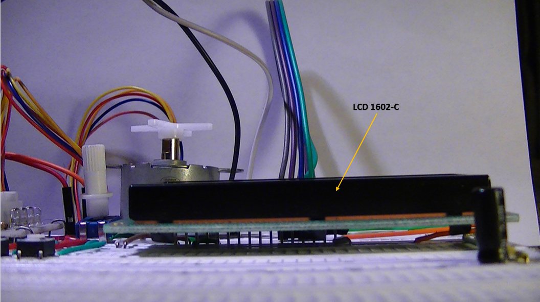
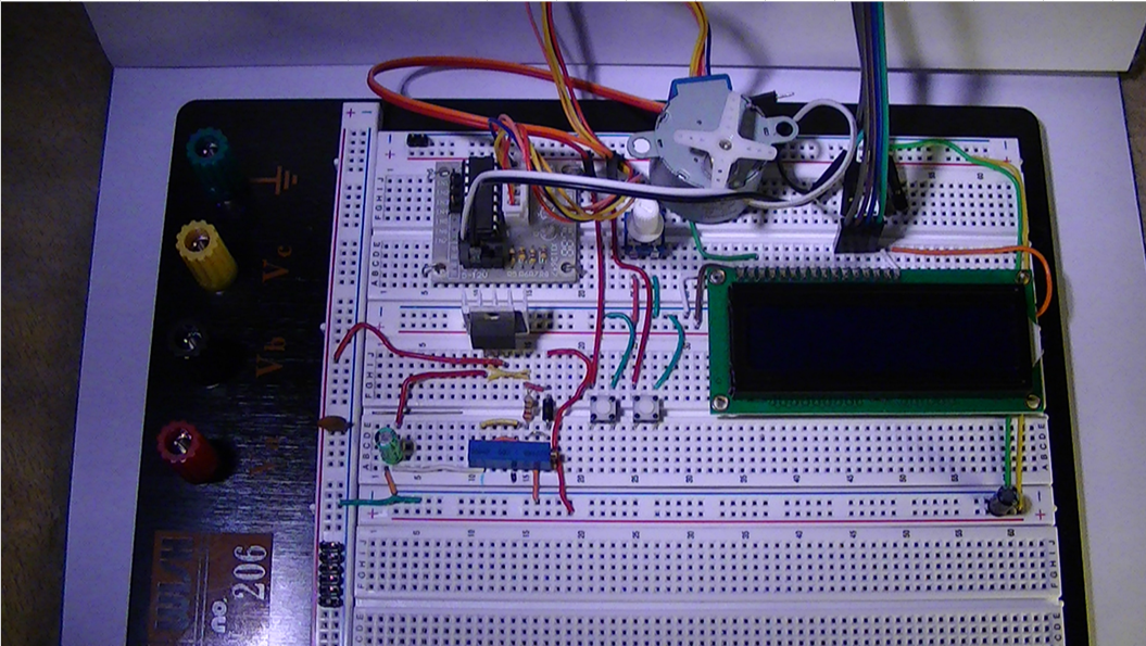
05/11/2017 at 19:01 • 0 commentsI've been working on this concept for awhile on the side for this project, it's incorporated directly into the Czerny-Turner configuration. Most of the prototype is on a 590 pin breadboard with an LCD screen (1602-C) to display data output., motor control, speed and temp ect.,
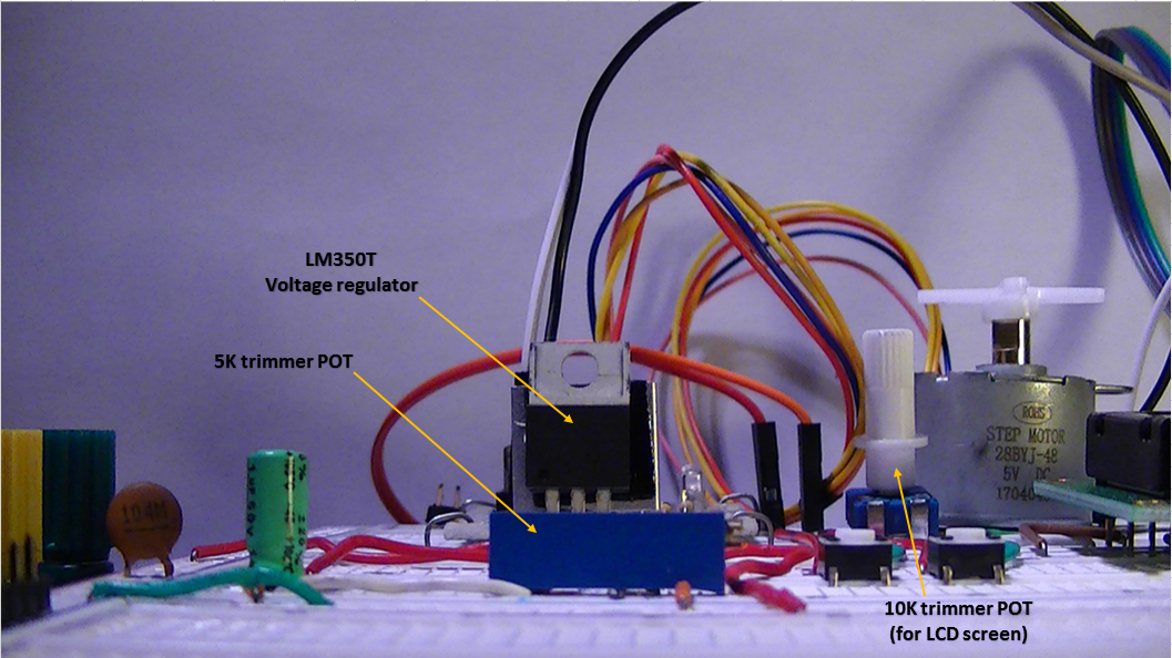
Here is the concept below with an explanation for each panel:
This is the voltage regulator that I am using to power the entire control circuit, it uses an LM350-T voltage regulator with an adjustable pin#1 (GRN) and a 217K resistor at pin#2 so it can be adjusted from 1.2vdc to 9vdc at close to 0.9A. with ripple rejection and circuit protection diode.![]()
This is a view from the power supply section of the board![]()
Here is the basic design concept, Czerny-Turner Configuration with a few more add-on's for a cleaner and more stable Raman signal (addition of beamsplitter/Dicrotic mirror) The turret sits of course between the 2 focal mirrors, it has 3 sides with different varying degrees of diffraction grating, example panel below;![]()
By rotating the turret, you can choose specific wavelengths![]()
This is the LCD display screen, I have code written to display MTR speed but I'm trying to figure out how to incorporate a more specific menu so I can track temp, and position.![]()
![]()
The proto board as it stands now
![]()
I was never an artist so please forgive me, this is a crude mock up of the turret and the specs for the motor and it's drive steps, I'm just wondering if the Atmega1284 can handle additional control commands into memory and still have enough breathing room to operate without crashing or latching up?
-
(ADC) AD7667/A Mounted on 48 pin Schmart Board W/New Heatsink
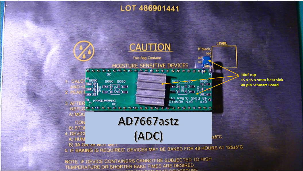
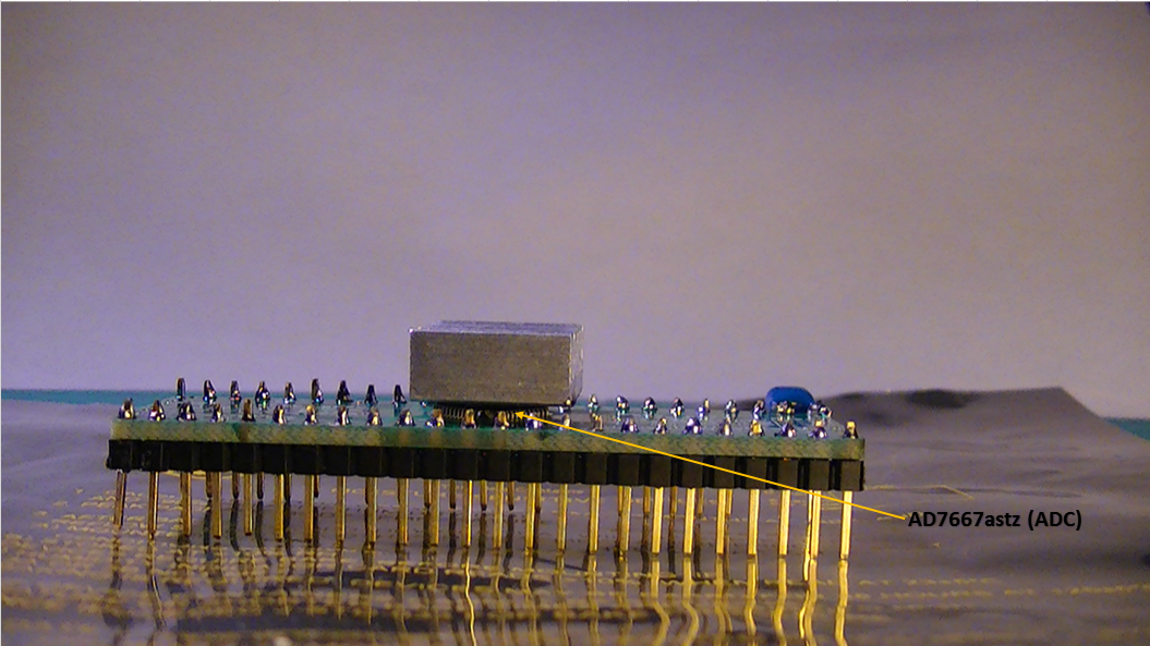
05/06/2017 at 16:58 • 0 commentsParts are in for the new updated circuit board for the CCD drv board, so I put together the 48 pin AD7667astz chip with the new heatsink mounted on it and the results are really good.
![]()
![]()
![]()
-
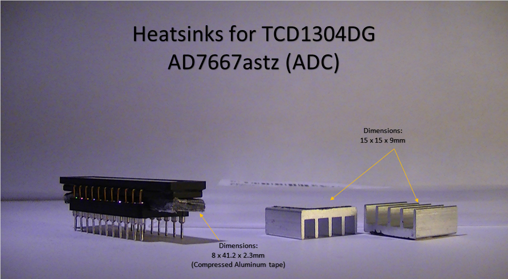
*Heat Sinks Added To TCD1304DG/AD7667A (ADC) for CCD Detector...
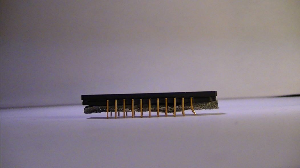
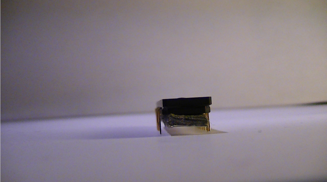
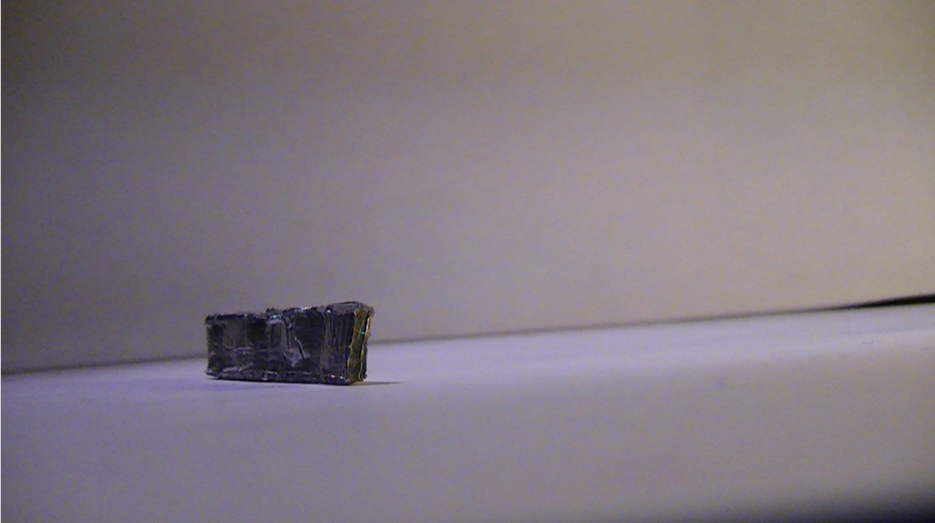
05/05/2017 at 19:14 • 0 commentsI got the idea for the heat sink for the TCD1304dg chip from @esben rossel he recently had a post where he showed how he cut a piece of aluminum block to act as a heat sink for the TCD1304 chip. That got me thinking, and so I formed my own aluminum heat sink out of aluminum industrial tape and will post the procedure also in my build files.
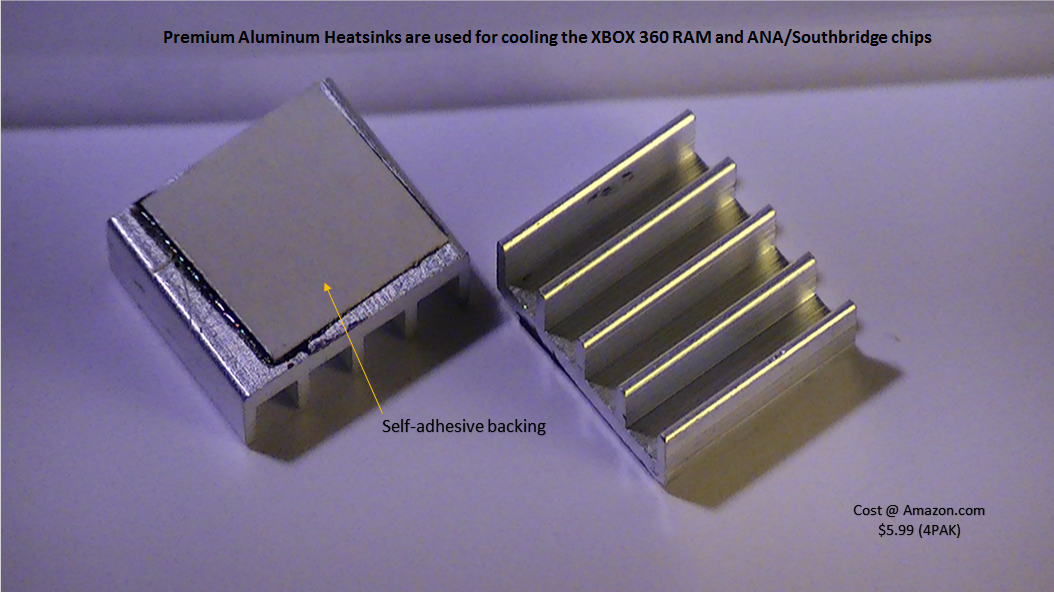
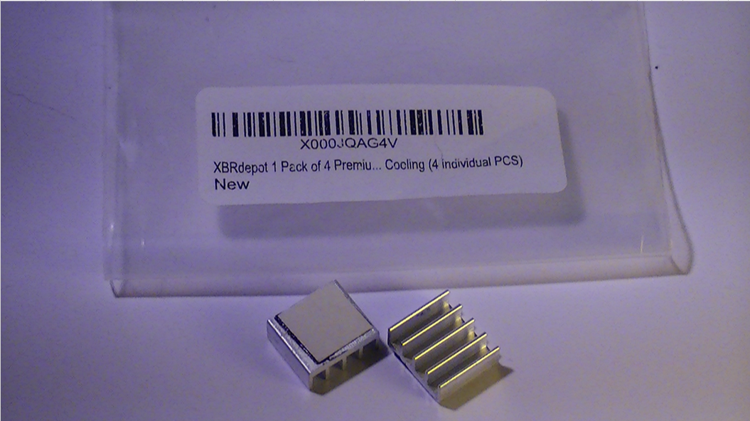
Also I found the perfect heat sinks for the AD7667 (ADC) chip, these little 15 x 15mm aluminum heat sinks are used in a kit for the Xbox 360, for the RAM chips inside, it cools them between 10-12 deg F. Perrrrrrfect :)
Here is the magic below;
![]()
![]()
![]()
![]()
![]()
![]()
![]()
![]()
![]()
DAV5 V3.01 Raman Spectrometer
The only thing worth doing, is the thing worth doing right!