-
1The basics - know your options
In this instruction I will talk about hardware options and potential usage ideas of the components. I will not go in the exact details and scientific explanations - there is not need for it because there are tons of excellent articles about all of them in the net if you want more in depth information about them
The processing unit
No matter what kind of function you want to implement, for now, a joystick, gamepad, controller will most likely be a USB Human Interface Device (HID). If you take a look at the USB specifications and how they are implemented - if you are not an absolute nerd or professional programmer - only thinking about implementing this on your own is a nightmare ;). But there are solutions out there that got you covered!
Right now I know of 2 microcontroller options that can act as an USB HID device out of the box:
- The Arduino Pro Micro
- The Tennsy USB development boards
The Arduino Pro Micro is the cheaper option but it is by far not as powerful as the Teensy 4 (more RAM, higher frequency...) The good question now is - which to take. Planning to work with multiplexers I played it save a chose the Tennsy to be on the save side.
![]()
If you have experience with the Pro Micro -> please let me know about it
Important Info: You can buy the boards with or without connectors on them. So if you do not have a soldering iron yet -> buy the preconfigured once!
Sticks
A game controller without any kind of stick - well for me - is not really interesting so we want to have sticks. There are 2 kind of sticks:
- analog sticks
- digital sticks
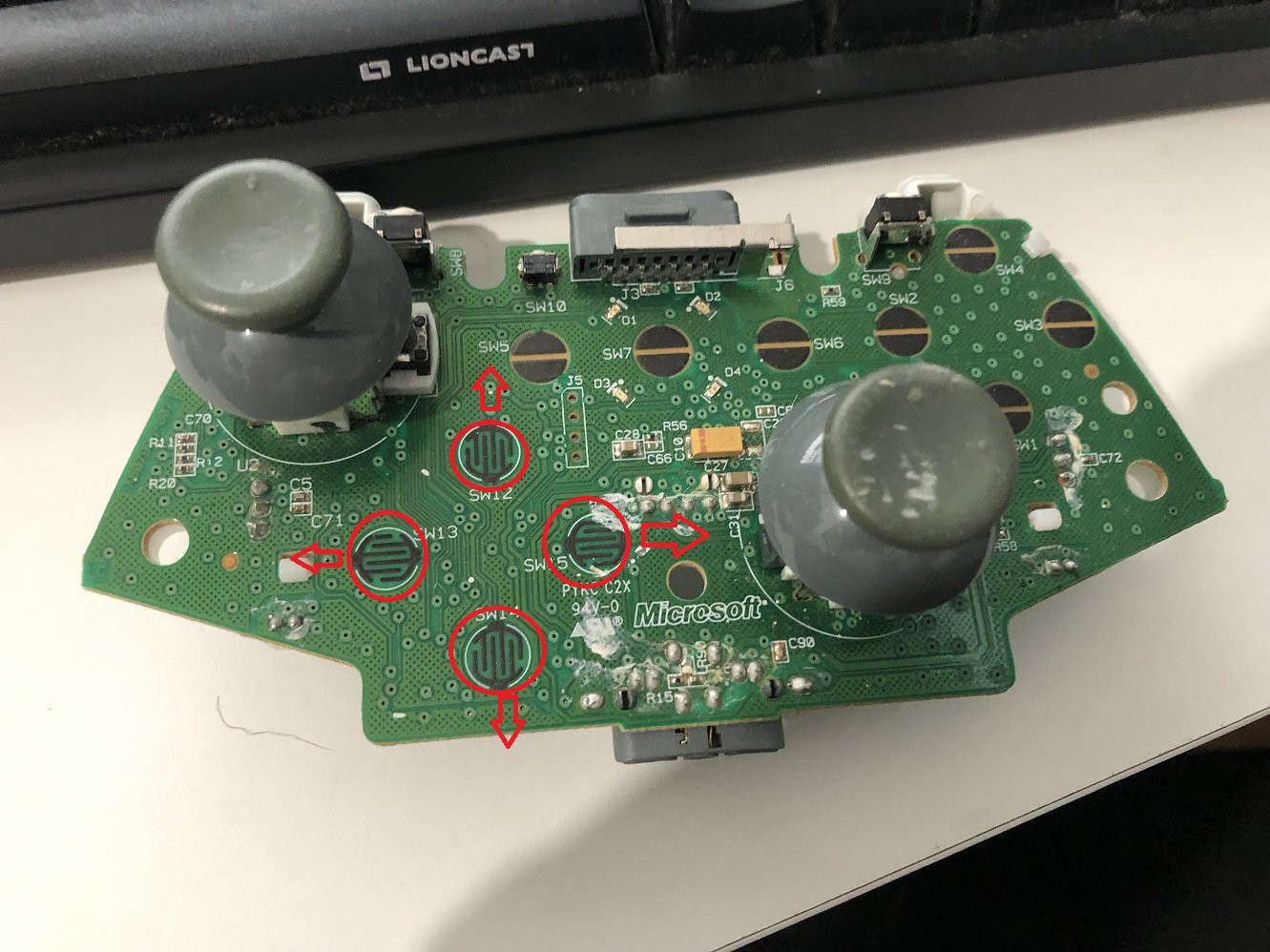
A digital stick is basically four buttons or micro switches that are triggered by some kind of physical mechanism . A good example is the direction pad on eg. the xbox controllers. Shown in this picture the switches on a salvaged xbox 360 controller
![]()
the characteristic of a normal switch is: it is on - or off ( 0 or 1 - digital..) there is no indication "how hard" the button is pushed.
Good thing on a custom gaming device -> you can choose in the code what kind of function ( a button press, a keyboard key, a mouse button) it will trigger. So it is pretty easy to build a digital stick on your own.The analog stick on the other hand is build out of at least 2 potentiometers. A potentiometer is basically a variable resistor that will let through more or less voltage. The microcontroller will read that input on an analog pin and will show it as a integer value between 0 and 1023. For example: If the joystick is in the middle / idle position - x and y axis both show a value round about 512. It might be of by 50 or something, that is not unusual -> that's what analog stick calibration is for :) If you push x axis to the left - value will decrease and reach 0 at the end - moving right it will increase up to 1023
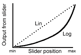
Very important: most potentiometers used in analog sticks work on a linear scale, meaning the value will steadily increase or decrease along the axis. The other type is logarithmic, meaning that the change of value differs along the axis. Something like this:
![]()
Try to go for linear ones for your project!
There are ways to transform logarithmic outputs to linear via code or wiring but this is making things very complicated. I had the bad luck that the 3 axis sticks I bought been linear on the x and y axis but logarithmic on the z rotate axis :(That said be also be aware that it is no problem at all to make an analog stick behave like a digital one in your code...
So my recommendation is go for analog sticks only!
![]()
But there is another very important limiting factor. Its not like you can add stick after stick and use them as analog axes and get away with it without problems. Windows ( I think it is actually DirectX but not sure about it) can only handle 6 axis!
X, Y, Z, Z rotate, Slider left, Slider right
So if you plan to use 3 sticks like I do at the moment, it is not possible to use all of them as analog axes. The little stick I use is either used to act as "wasd" input or arrow keys -digital if you like ...
Potential Use cases for sticks:
- Have one stick as your classic joystick -> x,y axes and maybe z rotate -> eg. to fly your plane or spaceship
- Use the second stick to move your head in game or for directional thrusters. Elite dangerous has a normal and alternative flight setting so you can have both options - as needed
- program one stick to act as a digital input -> eg simulate arrow buttons. It' s pretty cool to use the little stick under the thumb to navigate in game menus ,)
Buttons
Well Buttons are buttons and that's it for me and by that I mean Joystick buttons. Some of the sticks you can buy have a button included in the sticks as well.
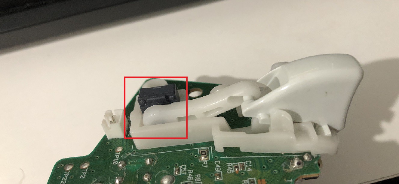
For me bigger buttons are better. But that depends on your taste. There are buttons with LEDs to illuminate the button when you push them and much more. So pick you poison there.Most if not all buttons are digital. If you wonder how the analog shoulder buttons on the xbox controllers work. That's done with a pretty nice concept.
![]()
It is actually a rotary potentiometer (red brackets) attached to a nice mechanic that will rotate the pot when pressing down the button.
If you use your imagination and scale this concept up - bam there is your option for the paddles of your next driving stick project ;)Toggles/switches
The main difference between a switch and a button is that a switch will stay in the position while a button will automatically jump back once you release it.
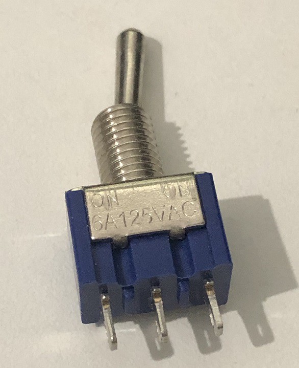
Most common are On/Off switches but there are also On-On switches. I bought On-On they look like this![]()
On-Off switches have "2 legs" while the On-On has "3 legs". I use mine as On-Off switches by just connecting 2 off the 3 legs because the number of pins used becomes an issue very quickly. More on this in anther instructions
The use for the switches are for me two main concepts:
- Use them as a keyboard key press -> logically it is like a "one state change - press and release a key (the same key usually)"
It is also possible to code it the way to act on status change -> key goes from on to off -> "M" key press and release. On to off -> "ESC" key pressed and released
eg. enter a map and leave it... - As the physical representation of an IF Statement -> "If the switch is on - the little stick acts as arrow keys - else the stick acts as 'wasd' keys"
Sliders
Sliders are just another type of potentiometer. For the microcontroller - they work exactly the same as described in the stick. From joystick perspective it is usually used as the Z axis or left/right slider
I think they are best known from those huge mix tables in music studios![]()
But be careful, as far as I read, especially in these studio equipment - logarithmic pots seem to be preferred!
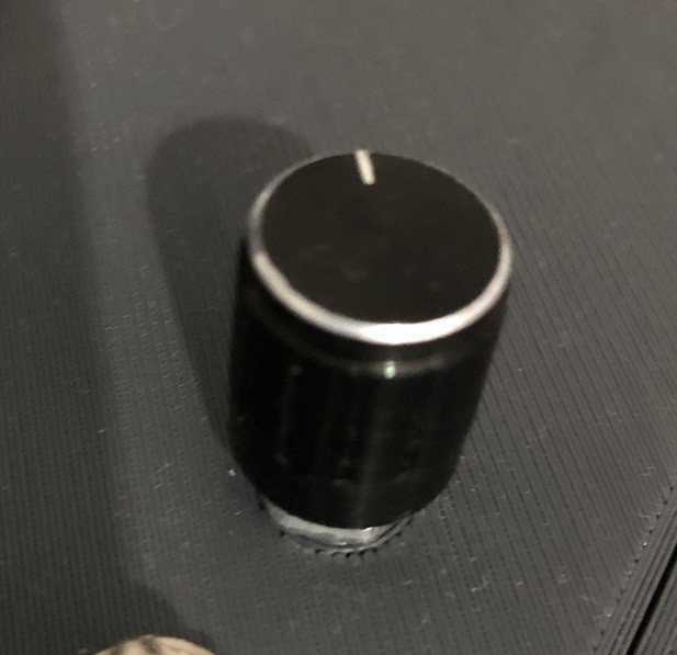
For a gaming device go for linear ones!Rotary knobs
Those thingys
![]()
The question you need to ask yourself on this is:
- Is the position of the knob meaning something -> like turn up the volume or throttle up and down
Then this knob will have a limit amount of turns or even only some degrees angle from low to high
=> go for a rotary potentiometer -> but keep in mind analog input requires an axis which are limited in the joystick implementation in Windows! - It is important to know in which direction the knob is turned -> like choose the next or the previous target in your space sim
The knob can be turned unlimited...
=> go for a rotary encoder -> they send a digital signal so you can eg. do a key press/release when turned left/right and so on
Rotary encoders often have a button included engaged when you press the knob. Tons of information about them in the net if you want to know how they work internally.
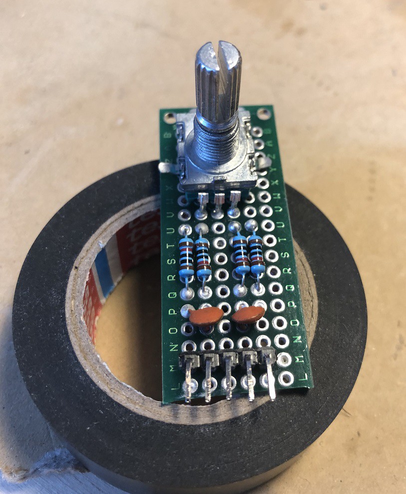
But one thing is worth to mention: They come in 2 flavors if you buy them!
The plane rotary encoders need a support wiring with capacitors and resistors if you want to do it by the books (maybe it works without - did not try it) You end up soldering something like this... ;)
![]()
In the spirit of: Why buy something cheap if you can build it for 2 times the money on your own *lol*
I recommend to go with breakout boards for the encoders. They are cheap and you are on the save site with them.
If you want to learn something and improve your solder skills - go for the plane onesDisplays
Lots of options here as well. OLED ones with color - without color. Lots of sizes. But this all is not worth anything if your micro controller cannot get it working :(
Especially the Teensy is very picky on this topic. Two main reasons:- Voltage for operations
- Availability of libraries
First thing is pretty obvious. The teensy operates only on 3 V while some controllers support only 5V or both. No clue what the Arduino Pro Micro supports
So if you choose your display - pay attention to the voltage they can operate on.The other thing is a bit more complex. While the teensy is arduino compatible with the teensyduino addon for the Arduino IDE - some libraries are not!
The only display controller that worked out of the box for me on the teensy is the SSD1306 with the Adafruit SSD1306 and GFX libs...
So pay attention to the display specs here as well!Finally connection options of the display. (O)LED Displays need a huge amount of pins if you wire them natively! So go for a breakout board with a dedicated controller here as well! I used a I2C based one but I guess SPI would work as well
Feel free to add your comments on this topic. I will gladly add additional info to this instruction if it is useful!
-
2The PIN problem
Now that you have selected your components. The info in this instruction is essential before you can start to wire up things!
A common problem for sticks with Arduinos / Teensy as controllers is the the limited number of pins the breakout boards have.
Since I am using the teensy board I will talk about this one only.
As you can see on the pinout https://www.pjrc.com/teensy/pinout.html the teensy 4 has 10 analog and 14 digital pins - where the analog pins can be used as digital pins as well.For my current setup there are:
- 2 x 3 axis sticks and one 2 axis stick plus an analog slide potentiometer -> 9 analog inputs
- 11 arcade buttons, 3 buttons overall on the sticks, 8 switches a rotary encoder with a button -> 23 digital pins
By using simple arithmetic ;-) it is easy to see that this will not work by directly wiring every input to a pin on the teensy.
So if you do not use this many components forget about the rest of the instruction. Wire them straight to your board - no problem
Else - there are 2 common approaches for the button problem:
- a button matrix
- a multiplexer
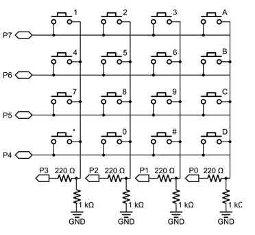
The Matrix
There are tons of excellent articles about the button matrix and a matrix button pad is included in most Arduino starter kits - so I will not cover all the details. Basically it looks like this
![]()
you wire the buttons in a matrix. In the above example the columns are used as outputs -> voltage supplied to them and the rows are inputs.
The code steps through all the output pins (columns) and reads the values on the input pins. Some would call his this method multiplexing ;)As far as I know there are also libraries available for Arduino which to most of the magic for you with debounce and everything. For my 23 digital pins I could have used a 5 by 5 matrix -> 10 pins for 23 inputs is not to bad of a deal.
But soldering this matrix in the actual stick seemed a bit annoying to me... ;). So I dropped this approach.
Further more there is no way to multiplex analog inputs from potentiometers - although this would not have been a a problem in my use case.
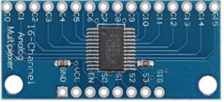
The (hardware) multiplexer
a good alternative for a guy with mediocre solder skills like me is a hardware multiplexer where all the wiring is happening in an IC/breakout board. The CD74HC4067 chip was the solution for me. it looks like this:
![]()
Its a 16 channel multiplexer (C0 to C15 in the picture). 16 decimal needs 4 bits to address (S0 to S3) and one signal pin to read the current input (SIG). This means you can read 16 inputs by utilizing 5 pins on your board.
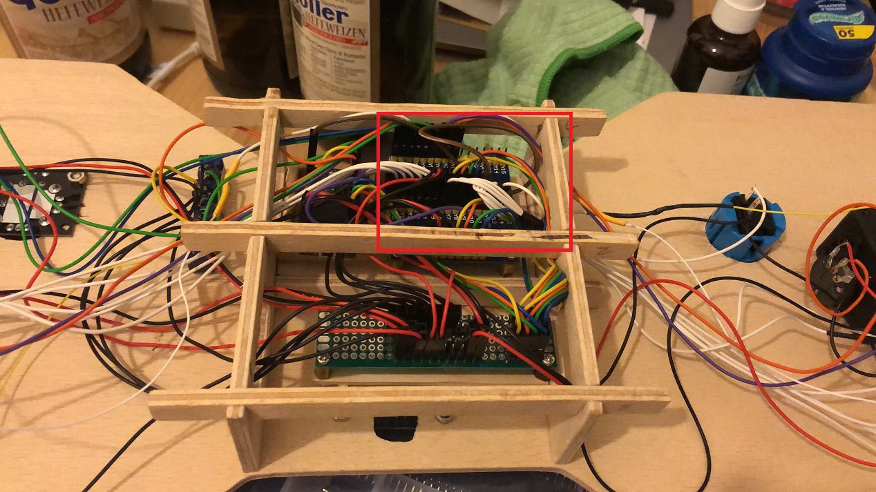
The code maybe a bit harder to read but the soldering is straight forward. One pin of the arcade buttons all to ground and the other one straight to the channel of the multiplexer. Where I decided to not directly solder the cables to the multiplexer - used dupont connectors to be a bit more flexible. This looked something like this in my stage 2 model![]()
The red square are the 2 multiplexers ( one for buttons, one for analog sticks) and all the white cables are the button inputs.
Summary
Do not forget to consider the "Pin Problem" in your planning.
Choose your preferred option and plan your wiring accordinglyAs always - feedback and comments are welcome
-
3Prototype wiring - Part 1: Flying wires
After choosing your components and thinking about the "PIN Problem" it is time to take the next step forward -> build a prototype.
Before we start: Most of the time I do not do a scientific approach. I more do an empiric approach.
- Build
- Test and/or fail
- rethink
- improve
- repeat
This means, most of the time I am not using any wiring plans at all and I tend to be very "pragmatic" - not to say sloppy - when setting up test setups.
I know of tools like fritzing and similar but that's not my thing, so for now - I will not provide any fancy wiring plans.But of course if you more like the scientific approach you should plan out your wiring with some software or on a piece of paper first... That said - lets start
I would not recommend to start with all the components together. It is better to start component by component and extend your functionality step by step. This way you will not loose the overview (that fast ;) ) and troubleshooting is much easier on a small setup.
Some small steps to go for test wirings may be:
- Get your first analog stick working as a joystick
- add some buttons to the setup
- add the sliding pot
- add some switches
For the (O)Led display I would recommend a separate test setup.
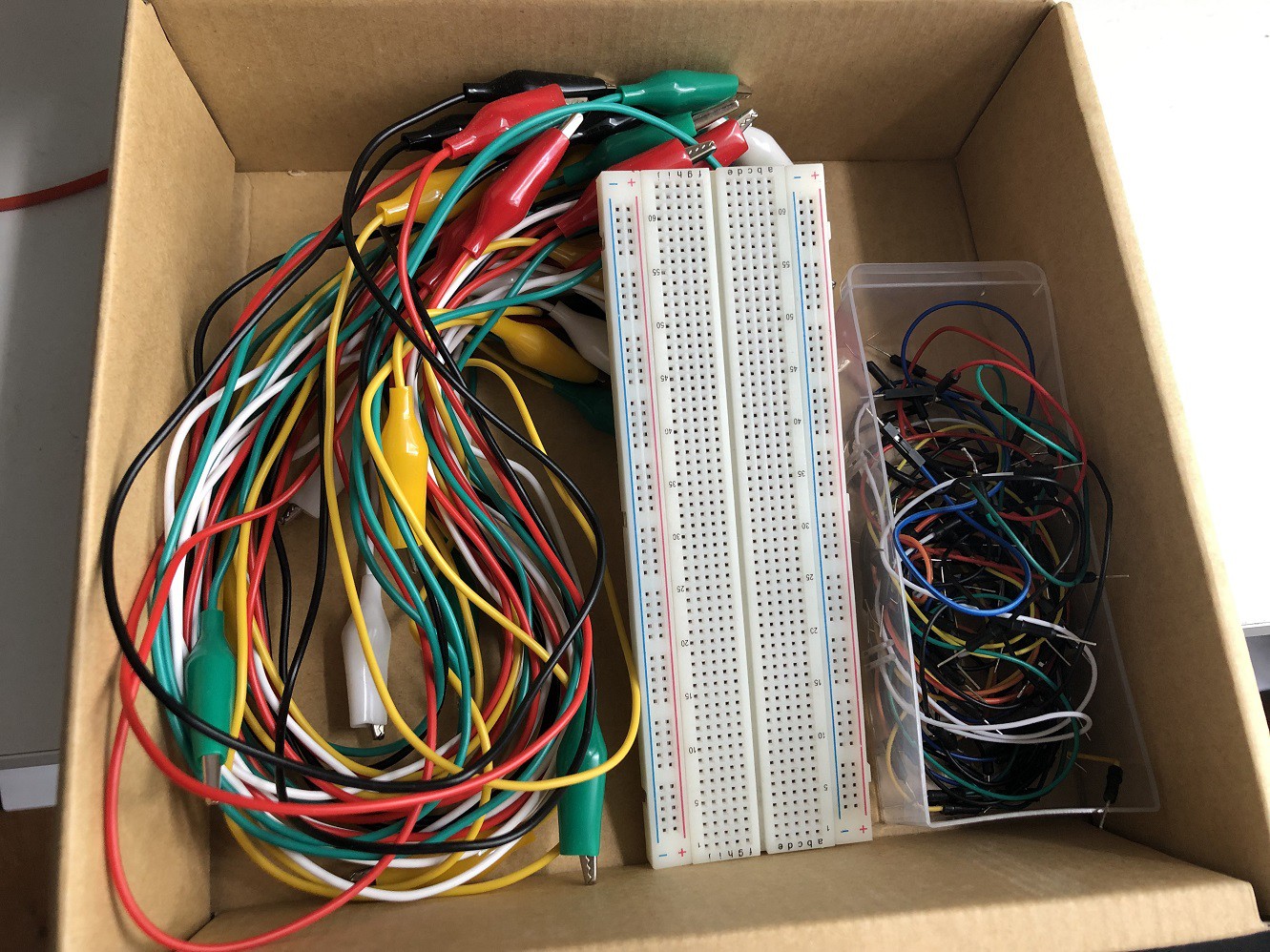
The way your first prototype may look like depends much on the equipment you have on your disposal besides your game devices components. There are some absolute essential in my humble opinion. Out of the box ( :-) ) these are:
![]()
If you own an Arduino already - 2 of them should be pretty familiar
- breadboard (in the middle)
- preconfigured cables with different dupont connectors (on the right)
Those 2 are included in pretty much every starter kit. Not that common there are the "Crocodile Clamp" cables (on the left).
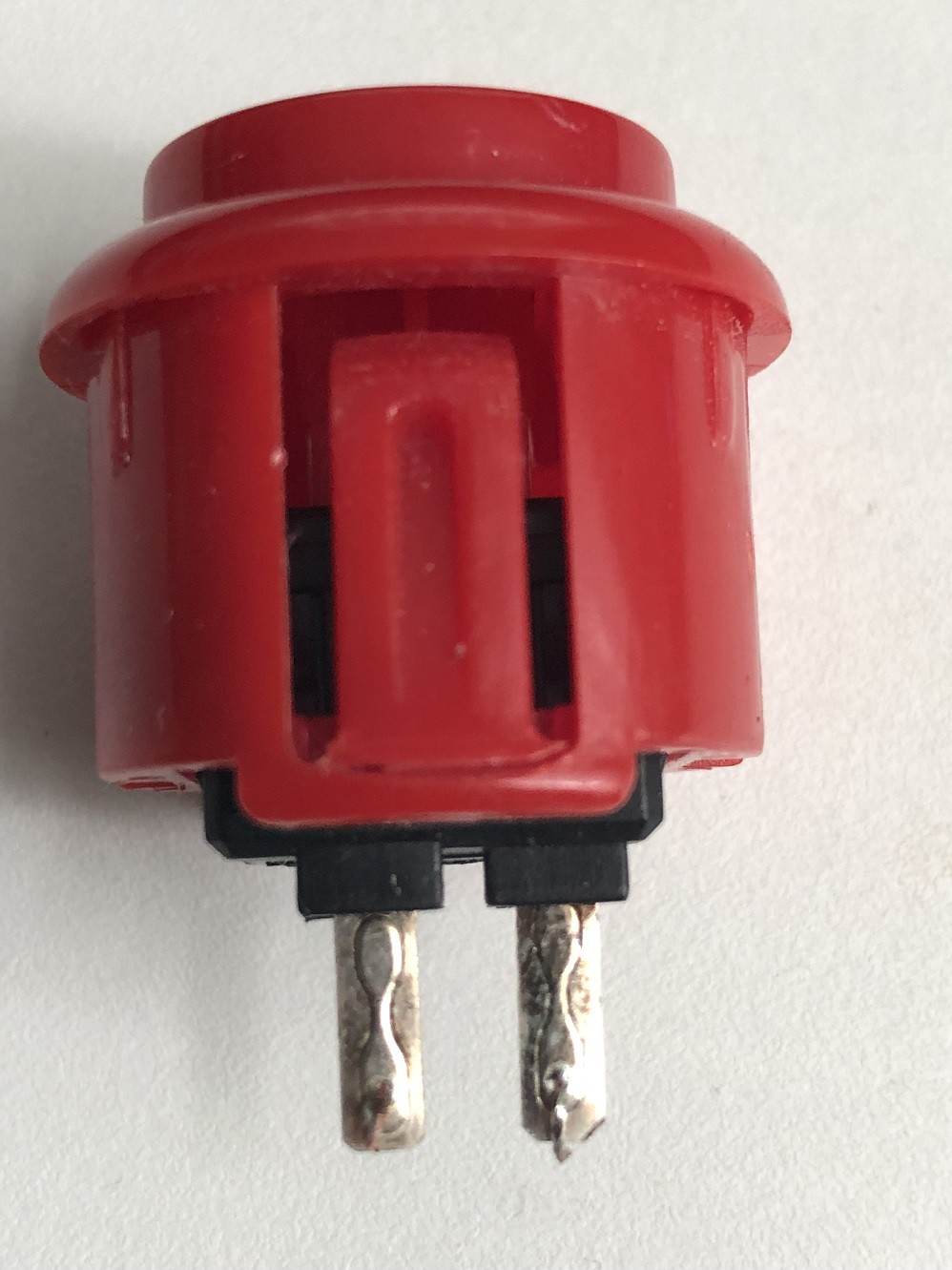
Well at least, that is what I call them. If there is another name in english for them -> let me know.The reason why they are so important is - a lot of the components will not come with any cables at all. Like arcade button, the big sticks and switches. Most of the time they are prepared to solder cables directly to them - with those little "legs"
![]()
For a prototype - I at least - do not want to solder anything. Maybe you do not have a soldering iron at all, for now. So the crocodile clamps are a good workaround. If you combine them with the female-female dupont cables you are all set!
![]()
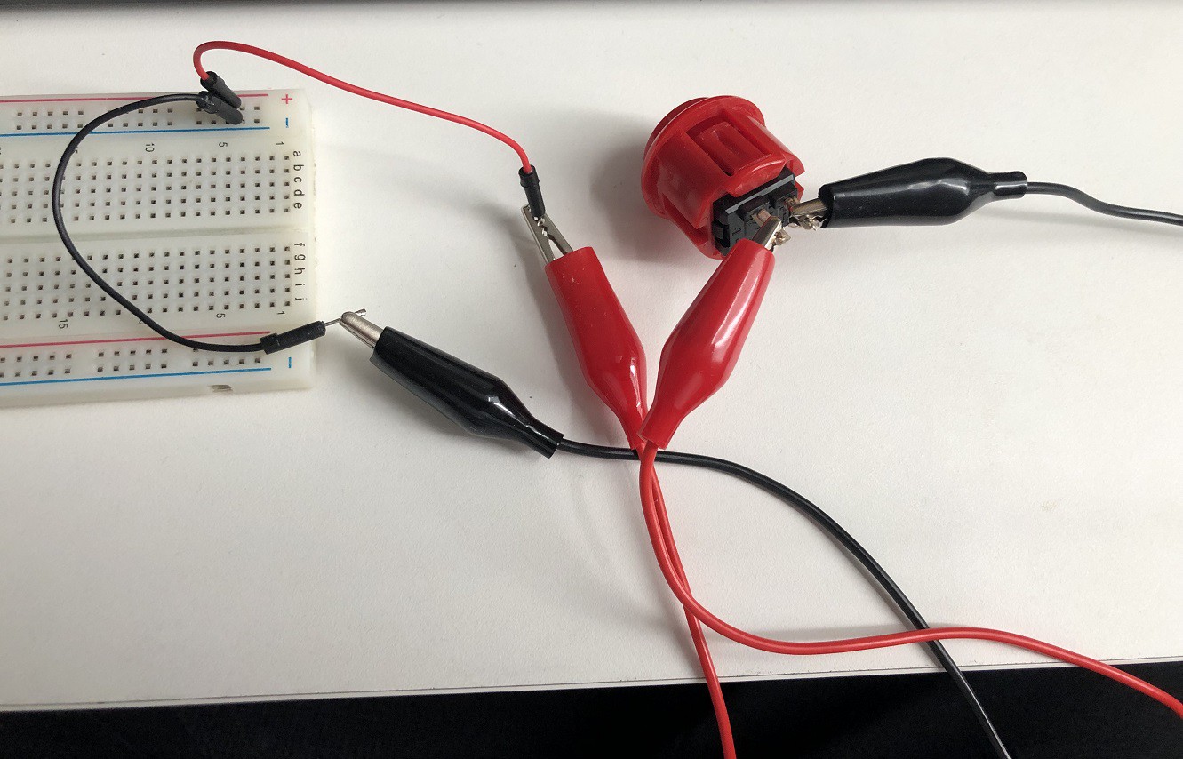
So a real life setup to test the dual sticks looked like this:
![]()
But be warned if you want to wire a complete prototype like this - things might get a bit messy ;)
![]()
Seems a bit stupid - but if it's stupid and it works... :o)
Of course all the wiring is not worth much if there is no code to support it. I will add Coding instructions later on. But if you want to start testing immediately checkout this tutorial for the teensy it has all info you need for a basic stick: https://www.pjrc.com/teensy/td_joystick.html
Next instruction will be on how to build a more durable, but still flexible wiring
-
4Prototype wiring - Part 2: Solder and Dupont connectors
As seen in instruction 3 - flying wiring is nice to do some test but on the mid to long run - this is not really an option. So at a certain point in time in your project you will have to use and/or learn two basic skills to get to the next level
- soldering
- crimp your own dupont connectors
I will be honest with you here, my solder skills are pretty mediocre. They are good enough to get things working. But I believe I should not be the one to teach you about soldering. There are some excellent vids out there on youtube and similar, where some really skilled folks show you how it is supposed to be done. So please check the net on how to learn soldering.
The next thing are dupont connectors. If you never heard about them I bet you have seen them before. They look like this:
![]()
You can buy preconfigured cables like the once in the starter kits or you can build your own cables with them. The big plus if you do so is you can choose
- cable length
- size of the connector (cables/pins in parallel)
freely
For that you need following parts (available as a kit or single)
![]()
Of course you need some cables. I use copper with cross section 0,14 mm2 eg in 10 meter bundles
![]()
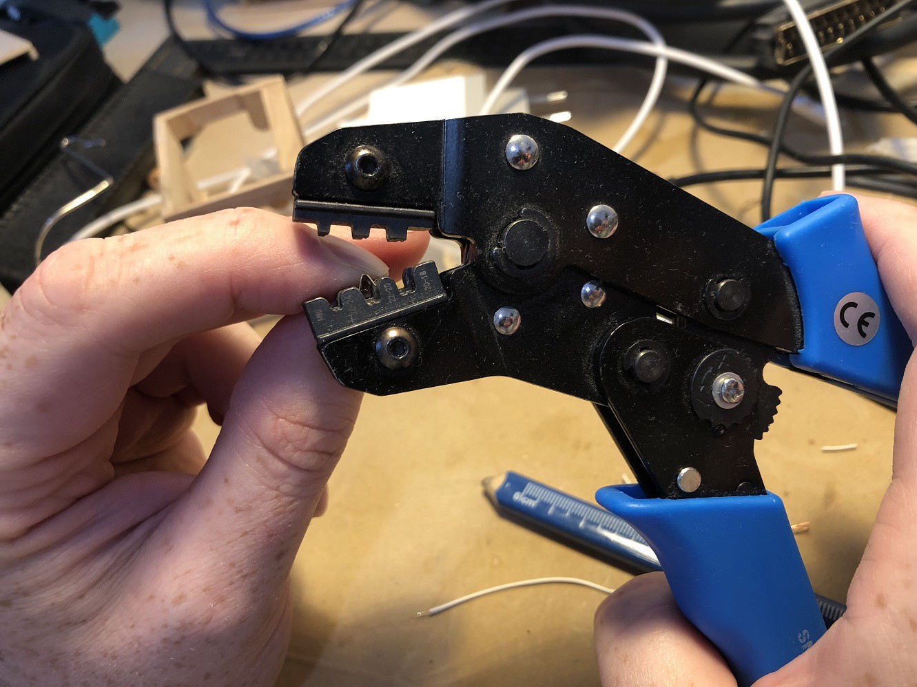
Finally you need a tool to attach the connectors to the cable. This process is called "crimping"
The tool is called crimping priers and looks like this:![]()
Pay attention to the brackets (marked in red) if you buy one. There are different types of brackets for different connectors. Some come with interchangeable brackets too.
Since we plan to crimp dupont... go for brackets for dupont connectors.A wire cutter is also needed to cut the cable to length.
I had no clue how to actually crimp the connectors to the cables. And I am still no expert on it. Despite there are quit some tutorials about how to do it (youtube and so on). They always lacked some details to make it actually work for me. So I will show you how I do it and will point out the things that where missing in the vids and that are important for me so the connector is working smoothly.
I will only show how to do it on a female connector, because for me they are more difficult to do properly. If you get it working on the female ones - male ones will be no problem at all.
First thing - those things are really tiny! Somebody with big fingers like me - will get there patience tested for sure :)
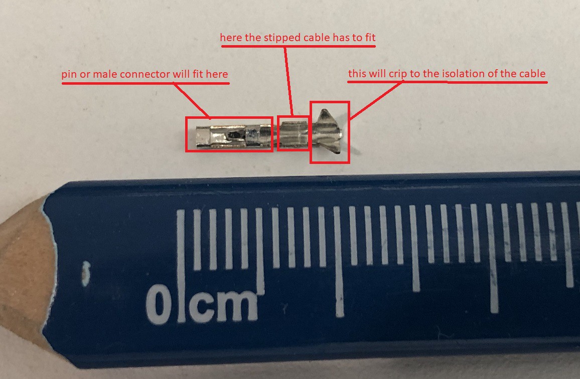
![]()
As you can see in the picture the connector can be divided into three parts
Maybe you can already see one of the problems that might arise.- If you tin the stripped cable it will get pretty stiff.
- If it is stiff but too long part of the cable will be in the section where the pin should fit
In this case you might get serious problems to push the connector on its counter part!
The length of the stripped cable therefore needs to be somewhere between 2 and 3 millimeters.Some pictures that follow are a bit blurry :o(
The phone did not focus correctly and I realized it to late- sorry maybe I will update the pictures with better quality ones laterNext thing to do is to prepare the wires
![]()
I usually remove the isolation a bit longer than needed because I only use a cutter. If you have a special gripper to remove insolation maybe you can do it a bit more precise/shorter. The workflow is as shown in the picture from top to bottom
- remove the isolation
- twist the copper litz wires
- tin the copper
- cut to length
It should look something like this
![]()
Even so the picture is blurry I think you can see that the cable is a bit to long and will most likely press against the pin if you try to connect later on. So if you just put the cable into the connector you can see if your length is right. You should cut the cable if it is too long. But be careful that you do not end like this
"I do not understand it - I cut the cable 4 times now and it is still too short!!!" :o)
If the cable is prepared take the connector into your thumb and pointing finger like this
![]()
This way you can correct the orientation of the little grip at the end by sliding your finger a bit against each other.
The way I hold the crimp pliers seems a bit odd at first but this way I feel I have the best control when the connector is put into the brackets.
![]()
Try to align the connector the way that the 2 lower end corners are pretty parallel to the lower part of the bracket. This way you can also see which bracket is the correct size. The connector will just fit the width on the upper end.
If you take a close look to the bracket you can see that there is a offset in the depth. Align the connector so it will touch this offset.
![]()
Gently close the pliers until the connector is fitting tight but it is not yet squashed.
![]()
The end of the connector should fit the corners of the bracket. As you can see - mine is a bit offset to the right. But that's still ok
Now put the cable into the connector. There is no real indication how far you should insert it.
My cable is already to deep into the connector![]()
This needs some practice - best is to trust your feeling the isolation on the cable should not touch anything before you close the pliers.
This is really the key moment that decides if the connector will be good or bad. If you think the cable is in the right position close the pliers. Not much force is need.
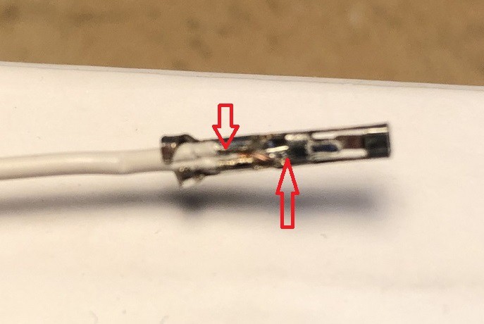
The connector will be somewhat stuck in the bracket. Remove it very carful so you will not bend it. In this case I ended with a pretty bad result. But I think it is more educational this way than it would have been perfect - also I did not do it on purpose ;)
![]()
As already shown in the picture above. The cable was inserted too far into the connector.
Some of the isolation ended up in the grip where usually the tined cable should be located (left arrow) and the cable therefore is where the pin later will be (right arrow).
This is not optimal so if you want to do it correct the only thing one can do at this stage is to pull the connector of again. The connector cannot be used after you remove it. So you have to start all over again.But it is also possible to continue at this stage.
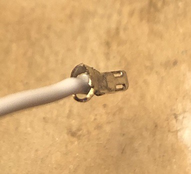
What usually happens with my pliers is that the end grip of the connector will not close completely
![]()
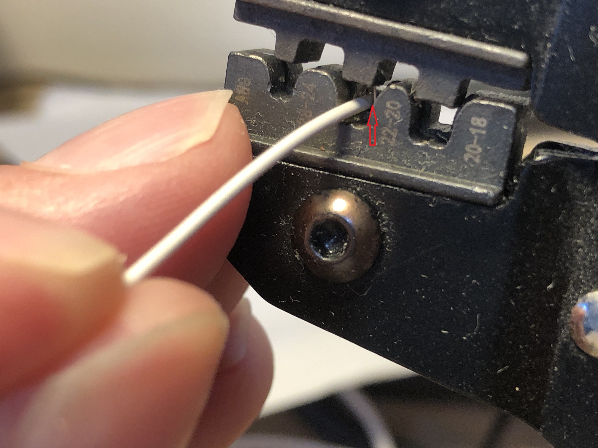
That can be fixed later on. In this example it was pretty obvious that the connector will not fit very well. But no matter if it looks good or bad I always do a simple test -> Push the connector to a pin eg. of a pin rail
![]()
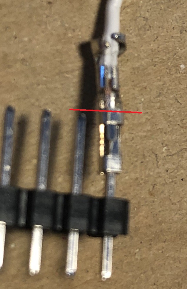
If no force is applied the connector will slide only half way to the pin. Now you have to options
- pull off the connector and do it again
- apply some force and try to push the tinned cable a bit back without loosening it too much
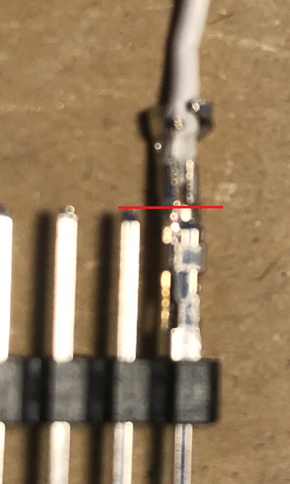
I usually try the second option. The trick is to hold the end of the connector not the cable and push straight forward. Otherwise you will bend the connector. In this example it worked
![]()
The connector will work this way but of course this is not the optimal way to do it. Even so the picture is blurry you may see that the isolation is still in the cable bracket. So most likely the tined cable bend because it was not tined completely. Never the less there should be a contact. But with some practice the connectors will fit pretty good and slides completely on the pin without much force.
Disclaimer: If you want to do it by the books - remove the connector and try again and again until you have a clean fit. My experience is that this dirty workaround works pretty well. And since there is no high voltage or current on the cable I do not see any harm. In the worth case the signal on the pin will be bad. But feel free to comment on this - what would you do?
Ok last step is to adjust the end grip (remember von above my pliers do not close it tight). Without the adjustment it will not fit the housing
![]()
Sometimes is not that worse. So it might be possible to push it in with a toothpick or something (tried and worked ;) ). But this is not a good idea. A better workaround is to take a plier with a smooth surface like this
![]()
Look on the connector from above/behind and align the pliers so it will push on the corners
![]()
Gently press them together. turn the cable a bit until you align the corners again. Usually you need to repeat this 2-3 times. Repeat until the grip is round a smoothly aligns with the isolation of the cable. Be carefully the end of the connector gets bend pretty easily on the length axis of the connector.
If you do it right you will end up like this
![]()
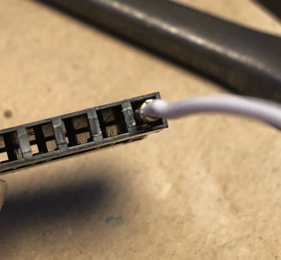
Now the connector should slide into the housing with almost no force at all
![]()
You will hear a little "click" as it will clip into place at the end. The little plastic nose in the housing will hold the connector in place if you push it onto a pin or counter connector.
Little tip - if you want to change the housing - this can be done. Just take a needle with a sharp point and carefully lift the nose a bit
![]()
Carefully pull on the cable until you can get the metal of the connector to remove the connector from the housing. Not much force is needed if you do it right. Be careful if you lift the nose too much it will break...
Ok - hope I could show you some of the pitfalls of crimping dupont connectors. But at the end of the day it depends on your practice and even more on some luck how well the connector will fit on the prepared cable...
-
5Hello World!!! - the first Joystick program
For this instruction I used following components:
- 1 x Arduino Pro Micro
- 1 x Analog Joystick breakout board
- 1 x Small push button
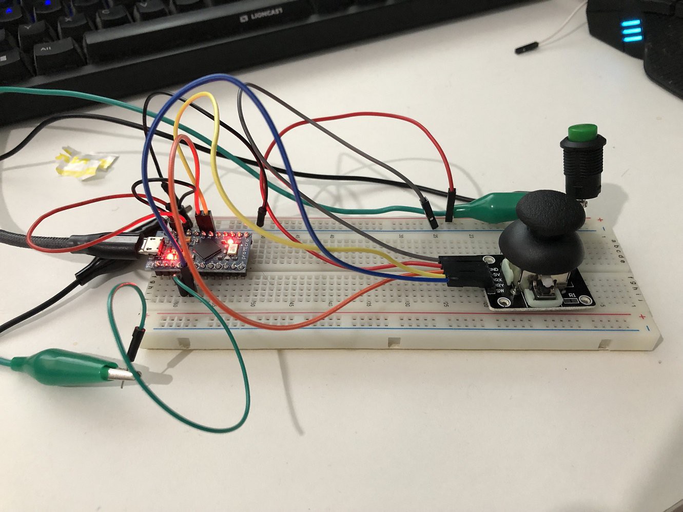
Using the flying wire method described in instruction 3 the test joystick looks like this
![]()
Preparation of the Arduino IDE
In my "bigger" joystick I used a Teensy 4 in this example an Arduino Pro Micro.
both need some preparations in the Arduino IDE.Teensy
The teensy is compatible to the Arduino IDE with the Teensyduino Add On. The installation is pretty straight forward as described at: https://www.pjrc.com/teensy/td_download.htmlOnce teensyduino is installed you can select as what kind of USB HID device it should act
![]()
if you select on of the option that includes "Joystick" nothing else needs to be done. All the joystick functions needed are included
Arduino Pro Micro
For the Arduino things work a bit different. A library is needed to get the board working as a USB HID device -> joystick.There are different ones out there. I decided to go with this one - since it works pretty similar to the one used for the teensy:
https://github.com/MHeironimus/ArduinoJoystickLibrary/tree/version-2.0Just download the zip file from github and add it to your Arduino IDE. If you never did this before here is a little hint where you can find the option in the IDE
![]()
And that's it for both
The Code
You can find the complete ino file of the code at:
https://github.com/Benksterinho/multi_axis_joystick/tree/main/simple_stickNow let's step through the code
the first thing is to include the joystick library we installed in the preparations and "construct" the joystick object
#include "Joystick.h"

// Create Joystick
Joystick_ Joystick(JOYSTICK_DEFAULT_REPORT_ID,JOYSTICK_TYPE_JOYSTICK,
  2, 0,                  // Button Count, Hat Switch Count
  true, true, false,     // X and Y, but no Z Axis
  false, false, false,   // No Rx, Ry, or Rz
  false, false,          // No rudder or throttle
  false, false, false);  // No accelerator, brake, or steering
there are a lot of options you can define there. If you want to go with the defaults you can just go with
#include "Joystick.h"

// Create Joystick
Joystick_ Joystick;  //  all defaults
In my case I knew that I do not have all possible axis in my setup and only 2 buttons -> the options setup the joystick that way
Next some variables get declared
// Debug flag
  bool debug = 1;
this is the debug flag - I like to use it so I can turn serial output on and off. It will be used in a simple "if" expression later on.
// Variables for Stick Values
  int stick_x;
  int stick_y;
  int btn_1;
  int btn_2;
These variables are not necessary at all - but the code is easier to read when using them - they will contain the current value on the pins later on
// Define the pins
  int pin_stick_x = A2;
  int pin_stick_y = A1;
  int pin_stick_btn = 3;
  int pin_button = 2;
Same here - it is not necessary to declare special variables for the pins but IMHO the code is far better understandable with them. Another advantage is - if you use other pins in your setup you can change them all in one place. These are the pins I connected my components to.
// Timer variable for triggers
  unsigned long joystick_timer=0;
  int joystick_trigger = 20;
It is not necessary, and very difficult if not impossible, to process the inputs in real time with this board (neither with the teensy but you have more options there -> interrupts on all pins). For a joystick it is good enough to pool the input every now and then. This 2 variables are used for the timing. More about the usage later on in the main loop
Next some things need to be setup so all the following snippets are in the Setup part of the program
void setup() {
  Joystick.begin();
The joystick library requires us to start the joystick. The begin function is called without any parameters -> defaults are used. The documentation of the lib states:
By default, all methods update the game controller state immediately.
That is good enough for now - we have no need for manual updates...// Buttons pinMode(pin_stick_btn, INPUT_PULLUP); pinMode(pin_button, INPUT_PULLUP);the 2 buttons are inputs and both connect against ground - so both are defined as INPUT_PULLUP. This basically means that the value on the pin is "1" if the button is not pressed - once pushed the value will be "0". For more background details you can check the official docs -> https://www.arduino.cc/en/Tutorial/Foundations/DigitalPins
  // Start serial debug output
    while (!Serial);
      Serial.begin(115200);
      Serial.println(F("Startup"));
}
The last step in the setup prepares everything so debug to the serial monitor is possible
Now for the Main loop
void loop() {
   // Process the Joystick
  if(millis() - joystick_timer > joystick_trigger)
  {
Polling in arduino can be done in two main ways:
- use the delay( ) function
- use the millis( ) function
There is tons of great in deep explanations in the net why the millis method is more flexible, not to say better. Just search for "millis vs delay arduino" in your search engine of choice...
In simple words it is like this:- delay will "stop the world" for the processor, while in delay the processor can not do anything else (not sure about interrupts -> I bet you can learn about it in the articles you can find in the net ;o) )
- the millis method on the other hand allows to have multiple triggers, with different timing, avtive in parallel
For this little joystick test delay would have been good enough but I consider it "good practice" to go with the millis method.
Short summary on how it works:
Millis returns a timestamp that tells how long the board is active since startup. The joystick_timer is substracted from that time and if the result is greater than the joystick_trigger variable then the IF-Block is executed. Since joystick_timer is initialized as "0" this is always true for the first itteration of the main loop. To prepare the next intervall of the trigger - the joystick_timer is set to the current millis timestamp in the IF-BlockNow its time to get some values of our connected hardware
stick_x = analogRead(pin_stick_x);
stick_y = analogRead(pin_stick_y);
btn_1 = digitalRead(pin_stick_btn);
btn_2 = digitalRead(pin_button);
The stick used is an analog stick with 2 axis X and Y. analogRead gets the current value on the stick PINs
The 2 buttons are digital therefore digitalRead is used to get there current valueif ( debug == 1 ) { Serial.print(F("Stick_X: ")); Serial.print(stick_x); Serial.print(F(" - Stick_Y: ")); Serial.print(stick_y); Serial.print(F(" - BTN_1: ")); Serial.print(btn_1); Serial.print(F(" - BTN_2: ")); Serial.println(btn_2); }; };Classical debug output to serial. The block just reports the values read before to the serial monitor -> of course only if the debug flag is set to 1
For all of you that pay close attention to the "{}" brackets... I just realized that the following code block might better fit inside the joystick trigger block... But for this example it does no harm if it is done in every iteration of the main loop -> if you like comment your thoughts on this
      Joystick.setXAxis(stick_x);
      Joystick.setYAxis(stick_y);
      if (  btn_1 == 1 )
        {
          Joystick.releaseButton(0);
        }
      else
        {
          Joystick.pressButton(0);
        }
      if (  btn_2 == 1 )
        {
          Joystick.releaseButton(1);
        }
      else
        {
          Joystick.pressButton(1);
        }
}
In this block the joystick library methods are used to let the Arduino behave like a joystick. First the X and Y axis is set to the current values.
Depending on the value of the buttons (remember 1 means not pushed" a button press/release is sendAnd that's it!!! ;
But since all this code is somewhat abstract here is a short vid how things turn out with this code on my setup
Hope you liked this little "Getting started" with the code
Happy codding!
-
6Solving the PIN Problem - Programming the hardware multiplexer
=> Work in progress... Will be finished soon <=
In instruction 2 you can read the reason and some possible solutions to "The Pin Problem"
In this instruction I will show you how to program the CD74HC4067 16-Chanal Analog Digital MultiplexerFirst a little overview on the wiring
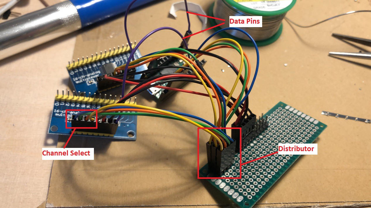
![]()
Shown above is a setup with two multiplexers (the blue boards). One multiplexer is used for the Joystick Axis and the other on for the arcade push buttons.
The multiplexer only has one data pin that connects to an analog pin on the teensy.
The data which is connected to the pin is selected with 4 channel select pins. The channel selection is set via a digital signal.
For all of you that are not familiar with binary notation of numbers. Here is a short introduction . As always - if you want to know all the details - there are tons of sources in the net that go in much more detail.
Basically it works like this:- A digital pin has either high voltage on it or low voltage - it is ON or OFF - 1 or 0
- Therefore one pin can describe 2 states 0 is the first state - 1 the second
- the number of possible states, in binary, can be evaluated as an exponential expression with 2 as base and the number of pins as exponent (power by? - did not really explain this in English yet...).
Like 1 pin -> 21 -> 2 possible states - The way exponents with 2 as base work is simple - if you increment the exponent by 1 (add another pin) the amount of possible states will double.
- The multiplexers used have 16 channels - 16 is 24 -> 4 pins needed to select every channel
The way this is done and what are all numbers from 0 to 15 in binary. Will follow shortly in the code.
Back to the logic how the multiplexer is implemented. The logical flow is:
- set the channel selector to channel 0
- read the value for channel 0 to a variable
- increment the channel by 1
- repeat until channel 15 is processed
Some thoughts on the variables for all the data:
Since we have a defined number of values (16) 2 ways are possible- use 15 individual variables
- use an array variable
In the examples I will do both -> named variables for the stick axis and an array for the buttons.
Now for the code (I will add a complete example script later on)
As usual let start with some variables - no libs need to be included
// MUX Sig/Data Pins
  int SIG_pin_JOY = 14;
  int SIG_pin_BTN = 15;
This defines to what pins the multiplexer data/signal out put is connected
// Define Pin Variables
// Multiplexers
  int pin_mux_ctl_1 = 0;
  int pin_mux_ctl_2 = 1;
  int pin_mux_ctl_3 = 2;
  int pin_mux_ctl_4 = 3;
The channel pins the multiplexer is connected to
// Variables for Stick Values
  int data_L1_x;
  int data_L1_y;
  int data_L1_z;
  int data_L2_x;
  int data_L2_y;
  int data_R_x;
  int data_R_y;
  int data_R_z;
  int data_SL;
  int hat_angle;
  int data_per_SL;
The named variables for all the joystick axis. The "big" stick used have an additional Z Axis. L1 means "left stick 1". SL means Slider.
// Variables for Buttons
  const int numButtons = 15;
  byte allButtons[numButtons];
  int button_map[numButtons];
Number of buttons constant and 2 arrays to handle the input of the buttons.
The button_map array is used to map the channel number on the multiplexer with the actual joystick button number later onpinMode(SIG_pin_BTN, INPUT_PULLUP);
Like in inctruction 5 - the buttons are wired against ground -> INPUT_PULLUP sets the "SIG_pin_BTN" to High/1 -> 1 means button is NOT pressed -> 0 means buttons IS pressed!
// Debug flag
  bool debug_axis = 0;
  bool debug_btn = 0;
The debug flags already know from instruction 5
// Timer variable for triggers
  unsigned long joystick_timer=0;
all steps that follow are in the setup loop
void setup()
  {
  // MUX Pins
    pinMode(0, OUTPUT);
    pinMode(1, OUTPUT);
    pinMode(2, OUTPUT);
    pinMode(3, OUTPUT);

    digitalWrite(0, LOW);
    digitalWrite(1, LOW);
    digitalWrite(2, LOW);
    digitalWrite(3, LOW);
Initialize the output pins for the channel selector and that all 4 to low -> binary 0000 -> 0 in decimal -> channel 0
  // Start serial debug output
    while (!Serial);
      Serial.begin(115200);
      Serial.println(F("Startup"));
Prepares serial output for debugging
  // Button map
  button_map[0]=10;
  button_map[1]=11;
  button_map[2]=12;
  button_map[3]=13;
  button_map[4]=14;
  button_map[5]=9;
  button_map[6]=8;
  button_map[7]=7;
  button_map[8]=6;
  button_map[9]=5;
  button_map[10]=4;
  button_map[11]=3;
  button_map[12]=2;
  button_map[13]=1;
  button_map[14]=15;
This is the definition of the button array. The array index represents the channel on the multiplexer the values are the joystick button number
  // Joystick set to manual
    Joystick.useManualSend(true);
}
This is a teensy specific way to set the transmission of the joystick data to manual -> this way all info (axis and buttons) are send in one batch
The main loop is pretty straight forward. Almost only functions.
I know some like to add the functions first and the main loop at the end. But I find this confusing.. ;)
So I will explain the functions right after.void loop(){ // Process the Joystick if(millis() - joystick_timer > 20){ joystick_timer = millis();This is the basic "millis" way to poll some actions every 20 milliseconds in this case. More on this in instruction 5
      get_values_analog_sticks();
      get_values_buttons();

      set_joystick_buttons();
      set_joystick_axis();

  Joystick.send_now();
    }
}
The functions called in the main loop + the teensy command to send the set data as joystick output over USB.
The names are pretty straight forward I guess:- gather the current values
- set them as Joystick command
send them over USB
Now the details for the functions
void get_values_analog_sticks(){
  for(int i = 0; i < 15; i ++)
  {
The get_values_analog_sticks function has neither input nor output.
The for loop starts at 0 and ends at 15 -> 16 channels of the multiplexerswitch (i) { case 0: data_L1_x = readMux_JOY(i); break; case 1: data_L1_y = readMux_JOY(i); break; case 2: data_L1_z = map(log_2_lin(readMux_JOY(i)),0,9,0,1023); break; case 3: data_L2_x = readMux_JOY(i); break; case 4: data_L2_y = readMux_JOY(i); break; case 5: data_SL = readMux_JOY(i); break; case 6: data_R_x = readMux_JOY(i); break; case 7: data_R_y = readMux_JOY(i); break; case 8: data_R_z = map(log_2_lin(readMux_JOY(i)),0,9,0,1023); break; } };Remember? For the axis I decided to use named variables. This switch-case block is used to assign the values read from the multiplexer to the right variable.
The number of the case block reflect the channels -> eg. Left Stick 1 X-Axis is attached to channel 0 -> Left Stick 1 Y-Axis is attached to channel 0 -> ...
so it is important to adjust your code to the way how you wire your sticks!Note: Forget about the log_2_lin functions in case 8 and 2 for now. Unfortunately the Z-Axis of the stick I bought have a logarithmical potentiometer on the Z axis. I will cover this special case at the end
Every case block uses function readMux_JOY to retrieve the current value of the active channel (represented by the iteration variable "i" ) and stores the value in the corresponding named variable.
int readMux_JOY(int channel){
  int controlPin[] = {pin_mux_ctl_1, pin_mux_ctl_2, pin_mux_ctl_3, pin_mux_ctl_4};
readMux_JOY has an integer as output -> the value read on the channel. And the channel to read on as integer input. All control pins are stored in an array
int muxChannel[16][4]={
    {0,0,0,0}, //channel 0
    {1,0,0,0}, //channel 1
    {0,1,0,0}, //channel 2
    {1,1,0,0}, //channel 3
    {0,0,1,0}, //channel 4
    {1,0,1,0}, //channel 5
    {0,1,1,0}, //channel 6
    {1,1,1,0}, //channel 7
    {0,0,0,1}, //channel 8
    {1,0,0,1}, //channel 9
    {0,1,0,1}, //channel 10
    {1,1,0,1}, //channel 11
    {0,0,1,1}, //channel 12
    {1,0,1,1}, //channel 13
    {0,1,1,1}, //channel 14
    {1,1,1,1}  //channel 15
  };
To understand this part you need to know what a "multi dimensional array" is. Search for "multi dimensional array arduino" in your search engine of choice - tons of good explanations our there.
muxChannel array has 16 rows with 4 columns in every row.
The second thing to remember -> binary notation of decimal numbers...
Every row contains the binary representation of the decimal number/channel in the comments but every digit/pin is a separate column
0110 = 6
1011 = 13
...//loop through the 4 sig for(int i = 0; i < 4; i ++){ digitalWrite(controlPin[i], muxChannel[channel][i]); }This block "dials" the channel, that was passed to the function as input.
The for loop starts at 0 (like most index arrays do) and stops at 3. Logically the loop iterates over the 4 channel select pins.
digitalWrite is used to set the new value for the pin. First parameter of digitalWrite is the pin number and the second parameter is the value to set.The iterator variable "i" logically represent the current channel pin. It is used to address the corresponding index in both arrays that are used in the paramters.
The pin number (first parameter) is drawn out of controlPin array. The way the array is setup this means:
- Iteration 0 results in: pin_mux_ctl_1
- Iteration 1 results in: pin_mux_ctl_2
- ...
Multidimensional array muxChannel provides the value for the pin to dial the right channel over all 4 iterations. Lets assume the function was called for channel 7
The way the array is setup this means:- Iteration 0 will address the array with muxChannel[7][0] -> row 7 column 0 (the first entry)
{1,1,1,0}, //channel 7 -> 1 - ...
- Iteration 3 will address the array with muxChannel[7][3] -> row 7 column 3 (the forth entry)
{1,1,1,0}, //channel 7 -> 0
  //read the value at the SIG pin
  int val = analogRead(pin_sig_joy);

  //return the value
  return val;
}
After the channel is "dialed" things are a little bit easier to understand again ;o)
analogRead is used to read the current value of the Signal/data pin of the multiplexer.
it is temporarily stored in variable "val" which is the return value of the function.
The step with the "val" variable is optional. I think the analog Read could be directly used with return as well.At this point - it has been a while that it started - function get_values_analog_sticks ends -> all Joystick axis are read and stored in named variable.
to be continued soon...
A guide to custom Joysticks
An attempt to build the "ultimate" guide to building your own custom game controller


Discussions
Become a Hackaday.io Member
Create an account to leave a comment. Already have an account? Log In.