-
Instruction 6 started
09/20/2021 at 20:19 • 0 commentsThe topic of instruction 6 "Solving the PIN Problem - Programming the hardware multiplexer" is a little bit more complex to explain. So I need to split the writing of it in several parts.
Right now the first part is done but it is not complete yet -> I will continue as soon as I find time for it! -
Instruction 5 finished
09/14/2021 at 21:47 • 0 commentsI was curios how things will work with an Arduino based board. So I spent some money on some additional components :o)
This was also a good opportunity to create an instruction on How to setup and code a simple joystickEnjoy!
-
Instruction 4 finished
09/05/2021 at 14:25 • 0 commentsFinished instruction 4 -> crimp dupont connectors. Hope the tips and errors I made there will help you to tune your way on how you crimp the connectors.
If you have further tips -> feedback is always welcome
-
Channing the structure of my project
08/26/2021 at 17:17 • 0 commentsI decided that the way I started this project is a bit chaotic and not very user friendly so I try to restructure things....
Further more I plan to switch the scope of the project even further to a guide -> focusing more on instructionsHope you like the changes!
-
V3 is live
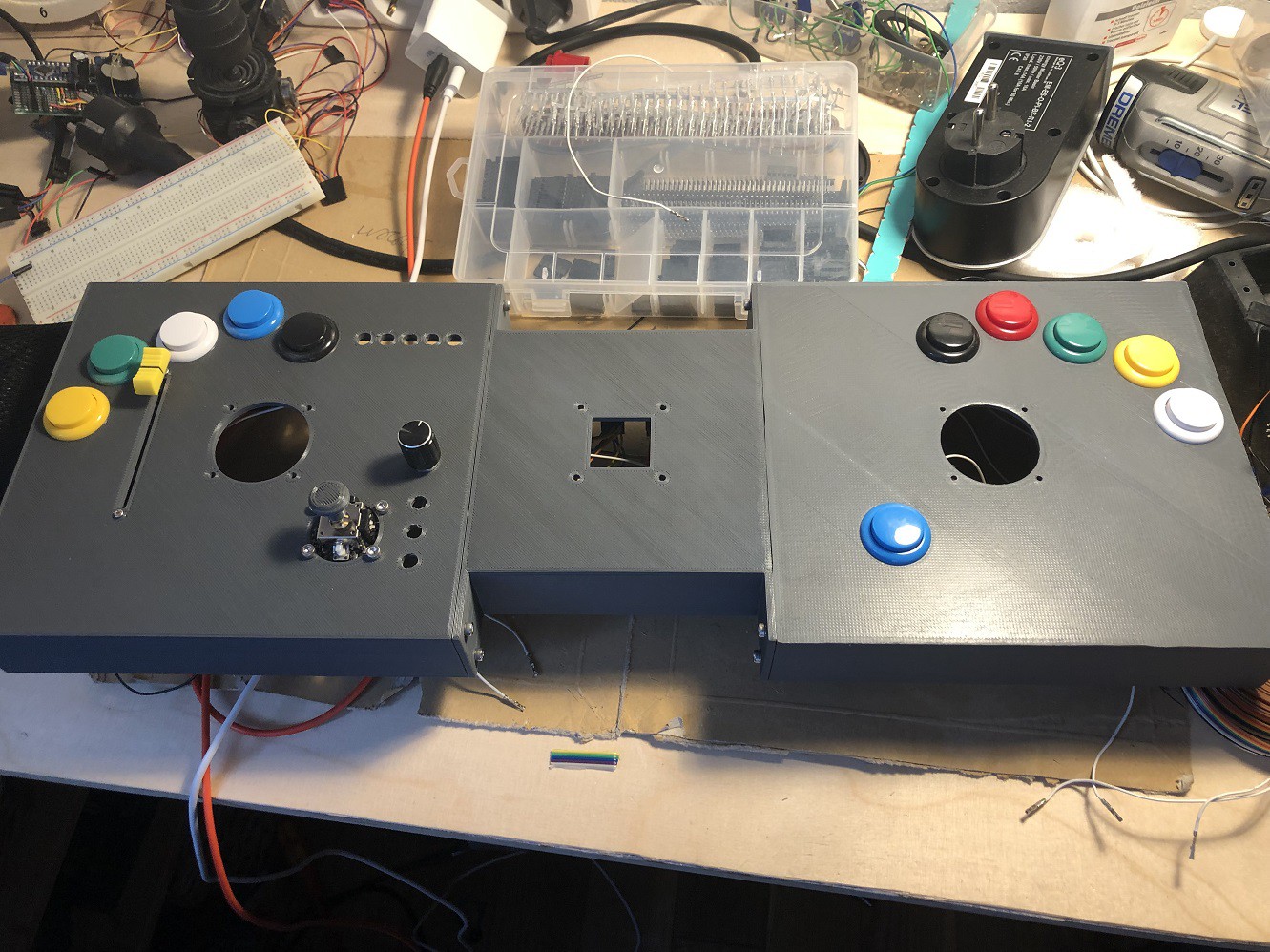
08/24/2021 at 21:59 • 0 commentsAll parts are now assembled
![]()
The basic wiring is done
![]()
Further more the code got its first overhaul. And is now also reflecting the new pin order.
I added it on github for more flexibility
https://github.com/Benksterinho/multi_axis_joystick
I will update the instructions soon.
Stay tuned :)
-
The construction of the body of the stick
08/23/2021 at 20:37 • 0 commentsI just added the FreeCAD file for the body of the the stick.
Warning: This is my first real CAD design so do not expect to much finesse in it :-)
If its stupid but it works...
-
3D Printed parts and basic wiring
08/23/2021 at 18:02 • 0 commentsAfter almost 40 hours of printing on the sidewinder. The basic body of the V3 Joystick is now ready.
![]()
For sure it is not perfect but for my first self constructed and printed assembly - I am pretty happy with it :)
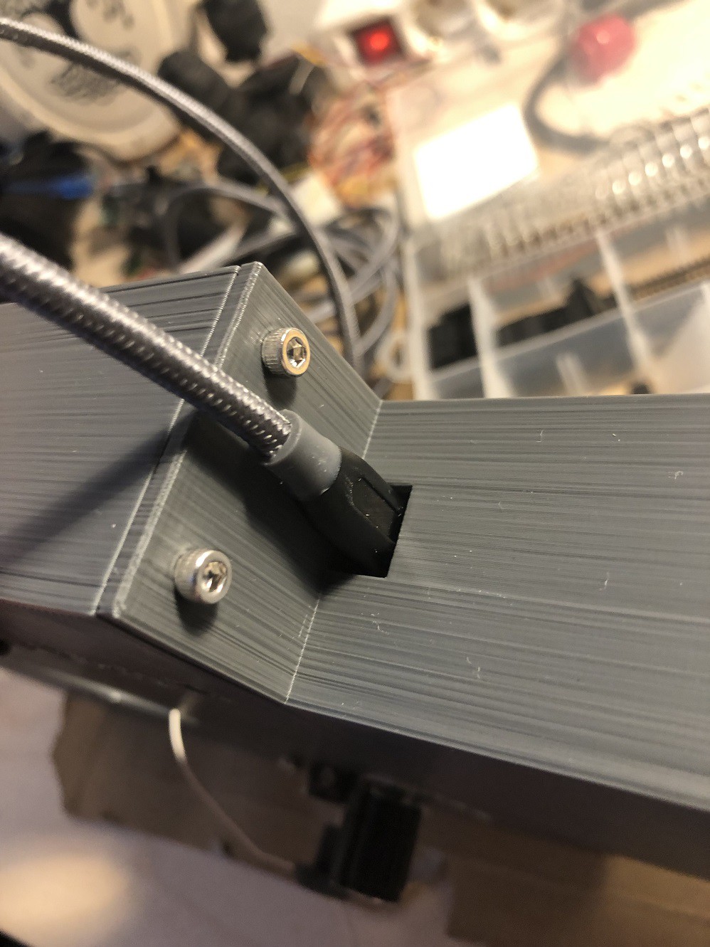
The center part is holding the breakout/processing boards. The heart of it is the teensy 4![]()
The fitting is pretty tight - so I have no idea if I ever get it our of there again...
The mini USB connector on the left is the main connector to the PC![]()
If somebody has tips on how to improve the printing feel free to share them to me. I did basic calibration and extruder setting but well I suppose it can be improved. But since I will not sell it - it's good enough ,)
I soldered a rail for all the GND and VCC connectors since the teensy only has 2x ground and 1x 3 volt pin
![]()
The 3x4 pins on the right are the signal pins for the multiplexer channel selection. I decided to address both multiplexers in one step -> the pins are vertically connected at the backplane. So it is not possible to independently select channels on only on of the two multiplexers. The teensy will poll the multiplexers (stick axis and buttons) every 20 milliseconds so I did not see any reason to have 2 separate loops. Check the instructions for the actual code.
Finally all is wired to the teensy:
Pin 0,1,2,3 for the channel selection -> yellow, orange, green, blue
Pin 14,15 as input pins -> violet, brown![]()
The components are:
upper right -> the teensy board
upper left -> the rail
bottom -> the multiplexers
Next step will be to wire up the buttons and connect the 3 analog stick.So stay tuned if you are interested :o)
-
The PIN problem...
08/21/2021 at 19:59 • 0 commentsA common problem for sticks with Arduinos / Teensy as controllers is the the limited number of pins.
Since I am using the teensy board I will talk about it. As you can see on the pinout https://www.pjrc.com/teensy/pinout.html the teensy 4 has 10 analog and 14 digital pins - where the analog pins can be used as digital pins as well.
For my current setup there are:
- 2 x 3 axis sticks and one 2 axis stick plus an analog slide potentiometer -> 9 analog inputs
- 10 arcade buttons and 8 switches a rotary encoder with a button -> 20 digital inputs
By using simple arithmetic ;-) it is easy to see that this will not work by directly wiring every input to a pin on the teensy.
There are 2 common approaches for the button problem:
- a button matrix
- a multiplexer
The Matrix
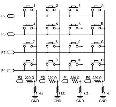
There are tons of excellent articles about the button matrix and a matrix button pad is included in most Arduino starter kits - so I will not cover all the details. Basically it looks like this
![]()
you wire the buttons in a matrix. In the above example the columns are used as outputs -> voltage supplied to them and the rows are inputs.
The code steps through all the output pins (columns) and reads the values on the input pins. Some would call his this method multiplexing ;)
As far as I know there are also libraries available for Arduino which to most of the magic for you with debounce and everything. For my 20 digital pins I could have used a 5 by 4 matrix -> 9 pins for 20 inputs is a good deal.
Further more there is no way to multiplex analog inputs from potentiometers - although this would not have been a a problem in my use case.
But soldering this matrix in the actual stick seemed a bit annoying to me... ;). So I dropped this approach.
The (hardware) multiplexer
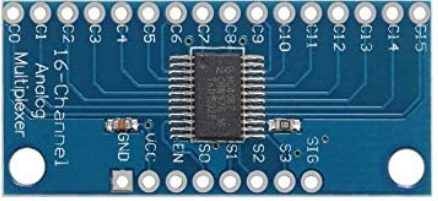
a good alternative for a guy with mediocre solder skills like me is a hardware multiplexer where all the wiring is happening in an IC. The CD74HC4067 chip was the solution for me. it looks like this:
![]()
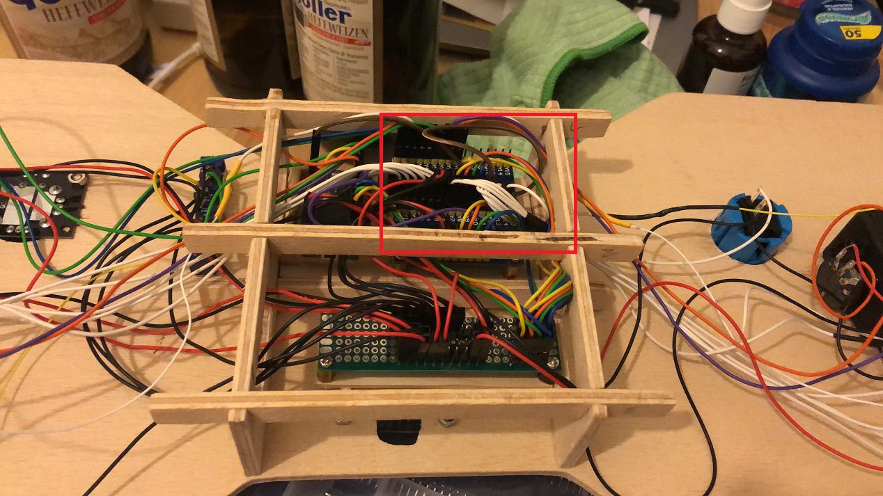
Its a 16 channel multiplexer (C0 to C15 in the picture). 16 decimal needs 4 bits to address (S0 to S3) and one signal pin to read the current input (SIG). This means you can read 16 inputs by utilizing 5 pins on your board. The code maybe a bit harder to read but the soldering is straight forward. One pin of the arcade buttons all to ground and the other one straight to the channel of the multiplexer. Where I decided to not directly solder the cables to the multiplexer - used dupont connectors to be a bit more flexible. This looked something like this in my stage 2 model
![]()
The red square are the 2 multiplexers ( one for buttons, one for analog sticks) and all the white cables are the button inputs.
I will give a instruction on how the code was implemented to use the multiplexers for a joystick later on
Hope you found this interesting :-)
A guide to custom Joysticks
An attempt to build the "ultimate" guide to building your own custom game controller