 GOAT INDUSTRIES
-
1Mechanicals
In previous projects we spent a lot of time designing and building the mechanical systems and we really wanted to short cut all the hard work by using a ready made system that could be bought reasonably cheaply 'off the shelf'. We looked at mobility scooters and ride on lawn mowers, but the electric quad bikes were super cheap ($800) and the build quality looked ok so we took the plunge and bought one brand new. After testing the machine on rough ground, we found that the standard motor did not have enough torque to be very useful, so had to throw it away and replace the whole drive train and motor controller with another, bigger, motor which had an extra in built gearbox to bump up the torque. Other than this, the mechanical build was quite straight forwards, with a series of small modifications such as a variety of sub frames and a mechanism for picking up the steering angle.
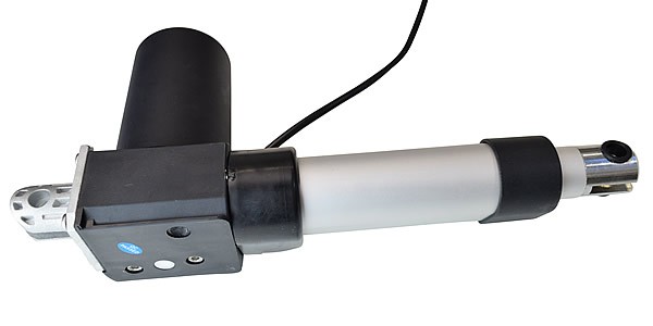
One of the key mechanical components was the linear actuator for the steering. The Gimson Robotics actuator detailed in the components section is capable of delivering a staggering 450 kg of force, which is more than enough to push / pull the steering, even at when mounted close to the vertical axis of the steering column.
![]()
![]()
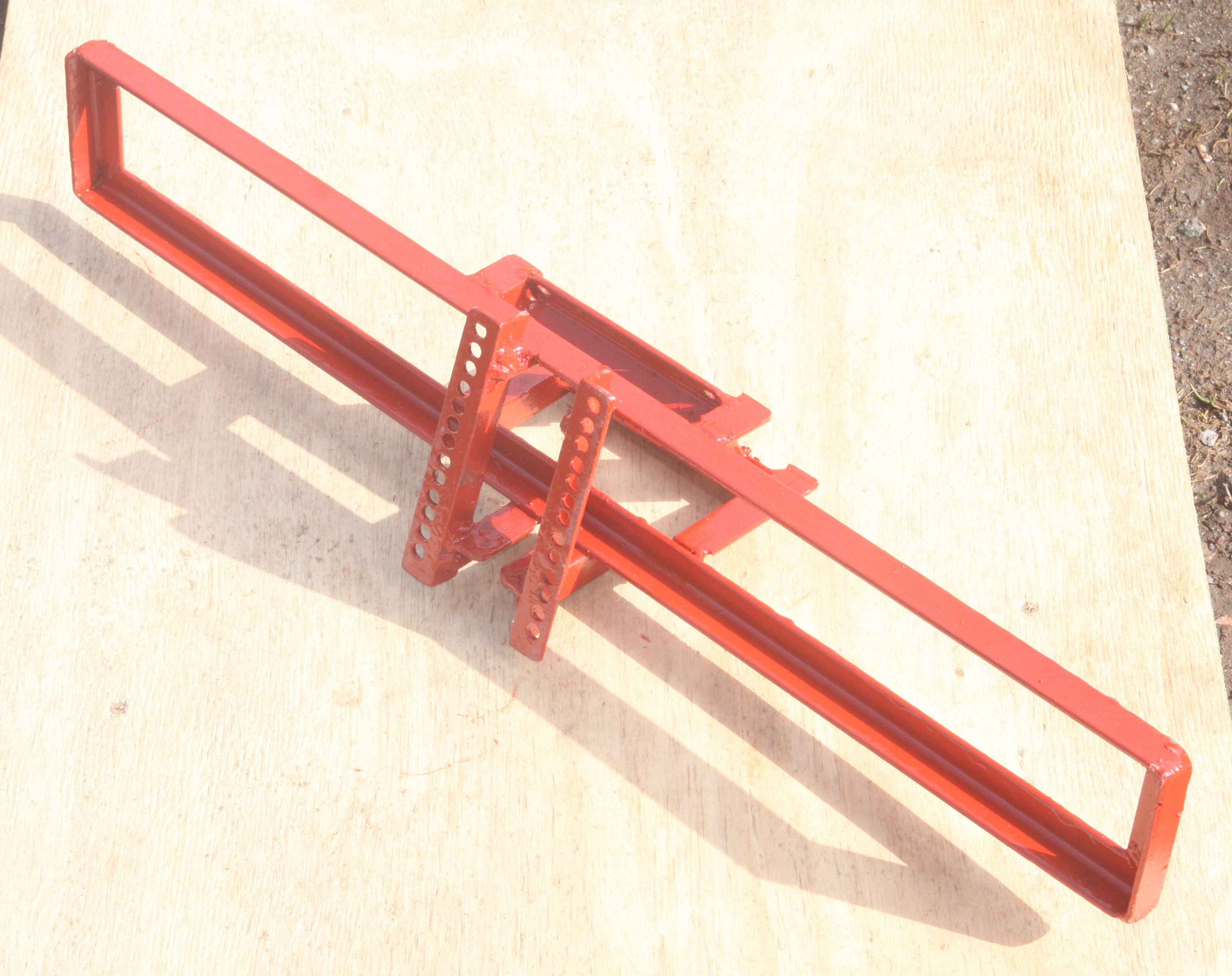
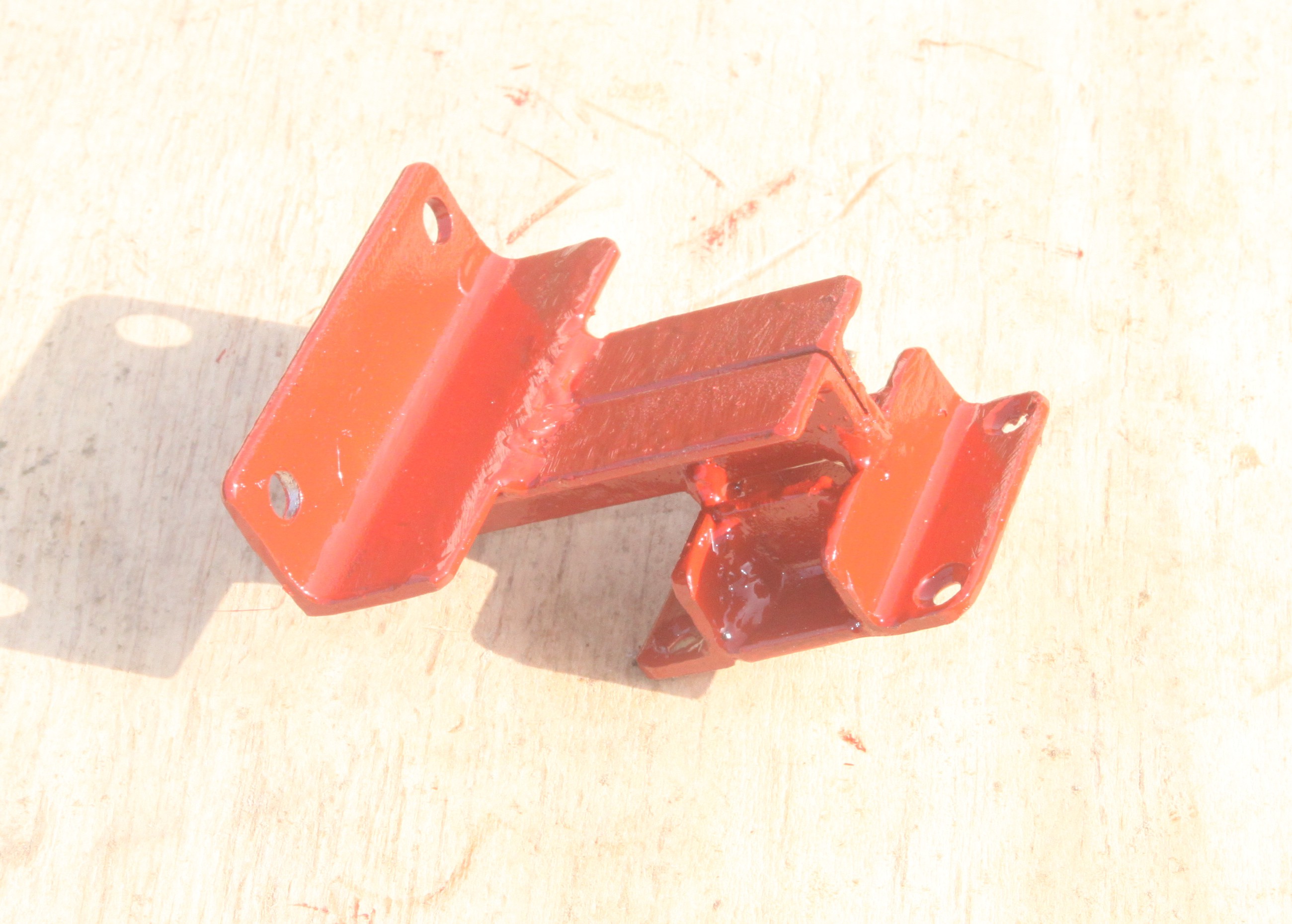
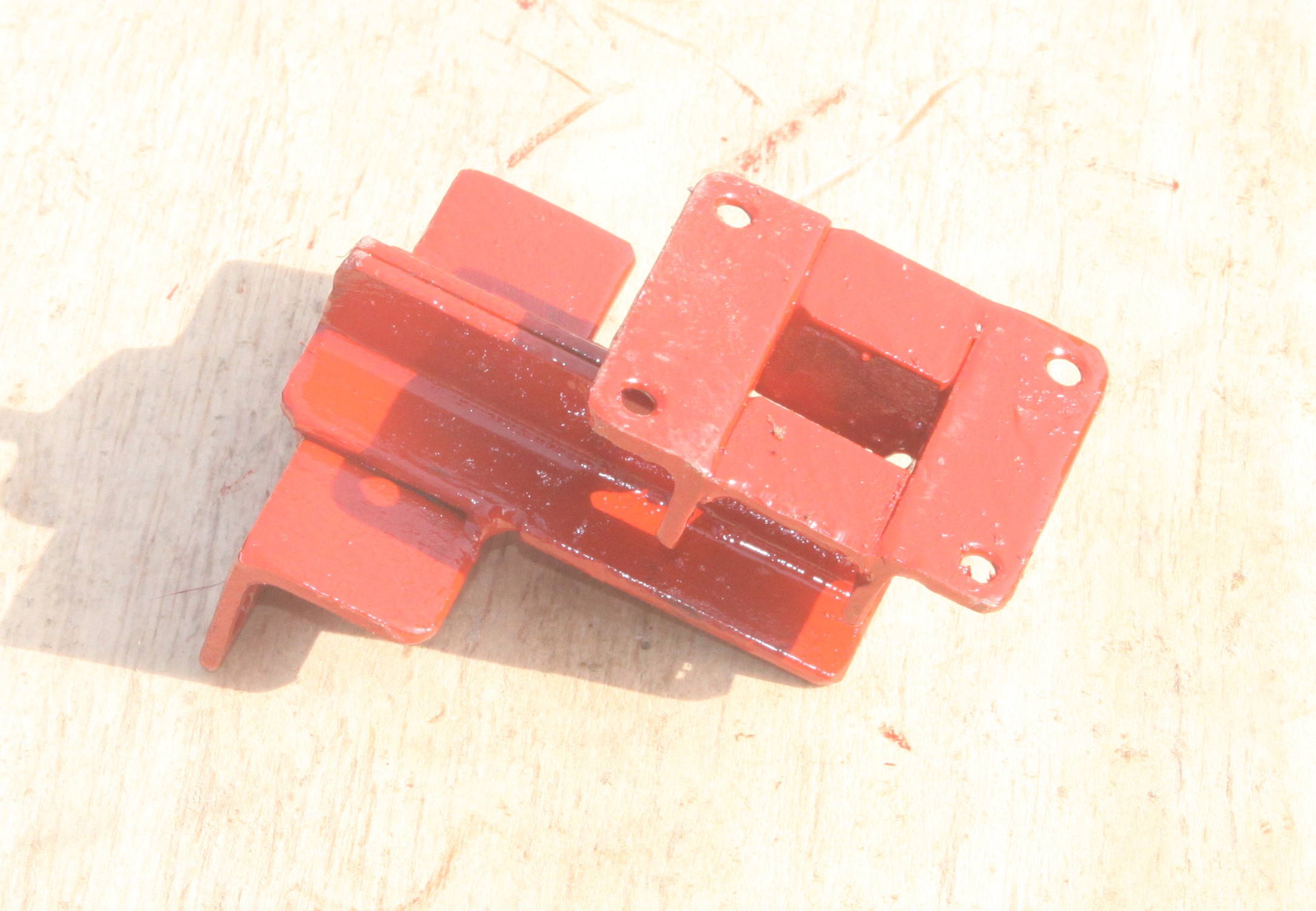
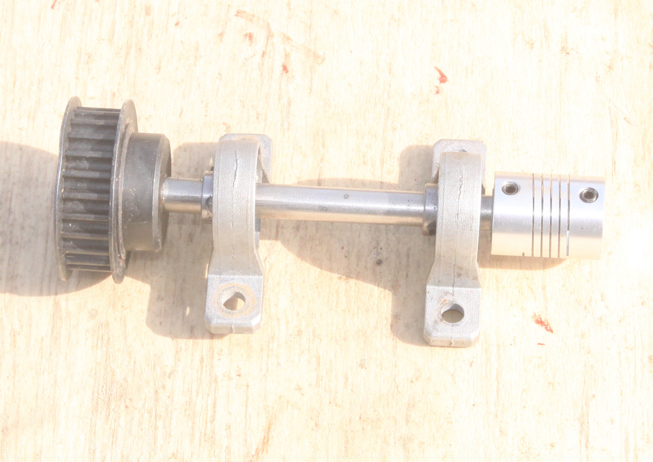
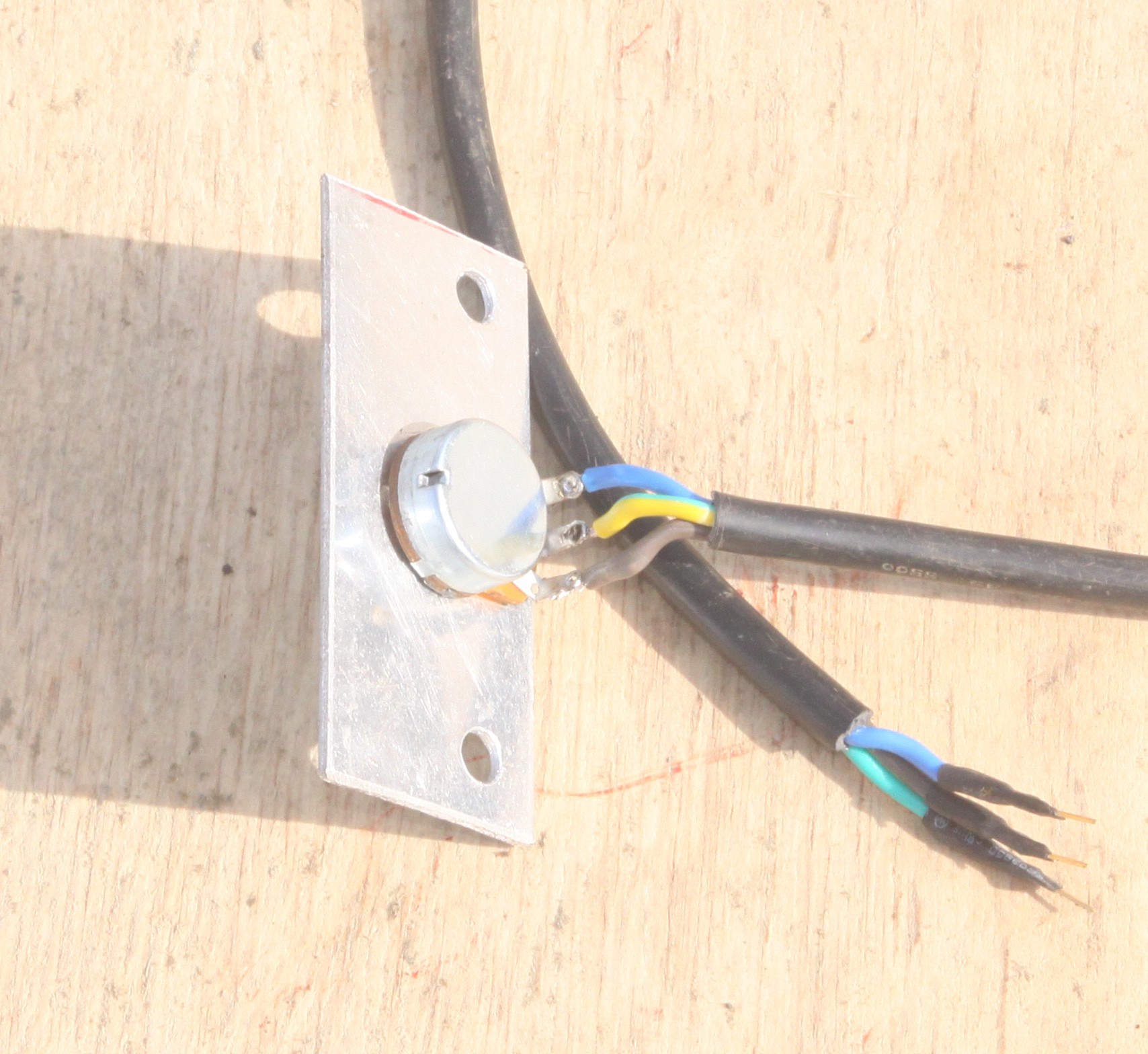
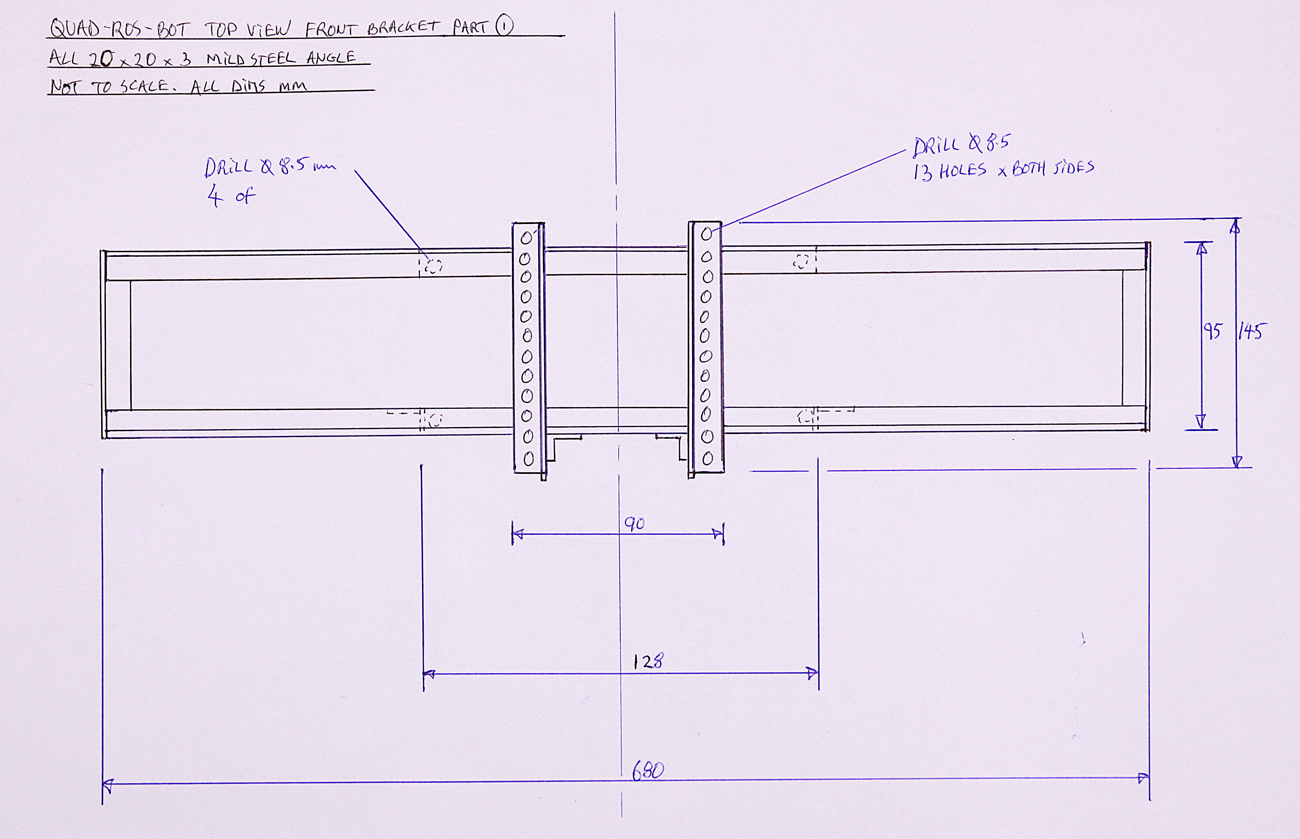
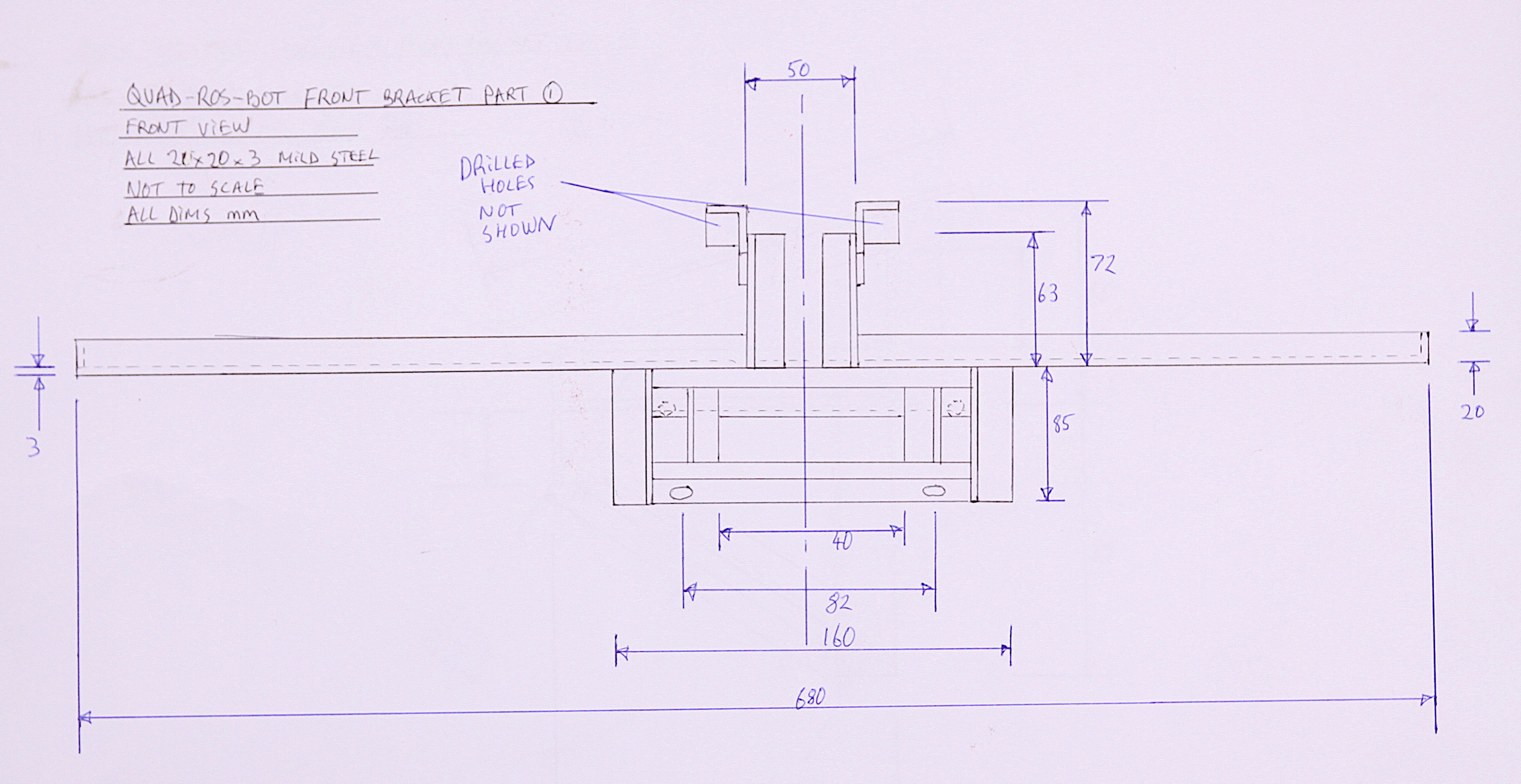
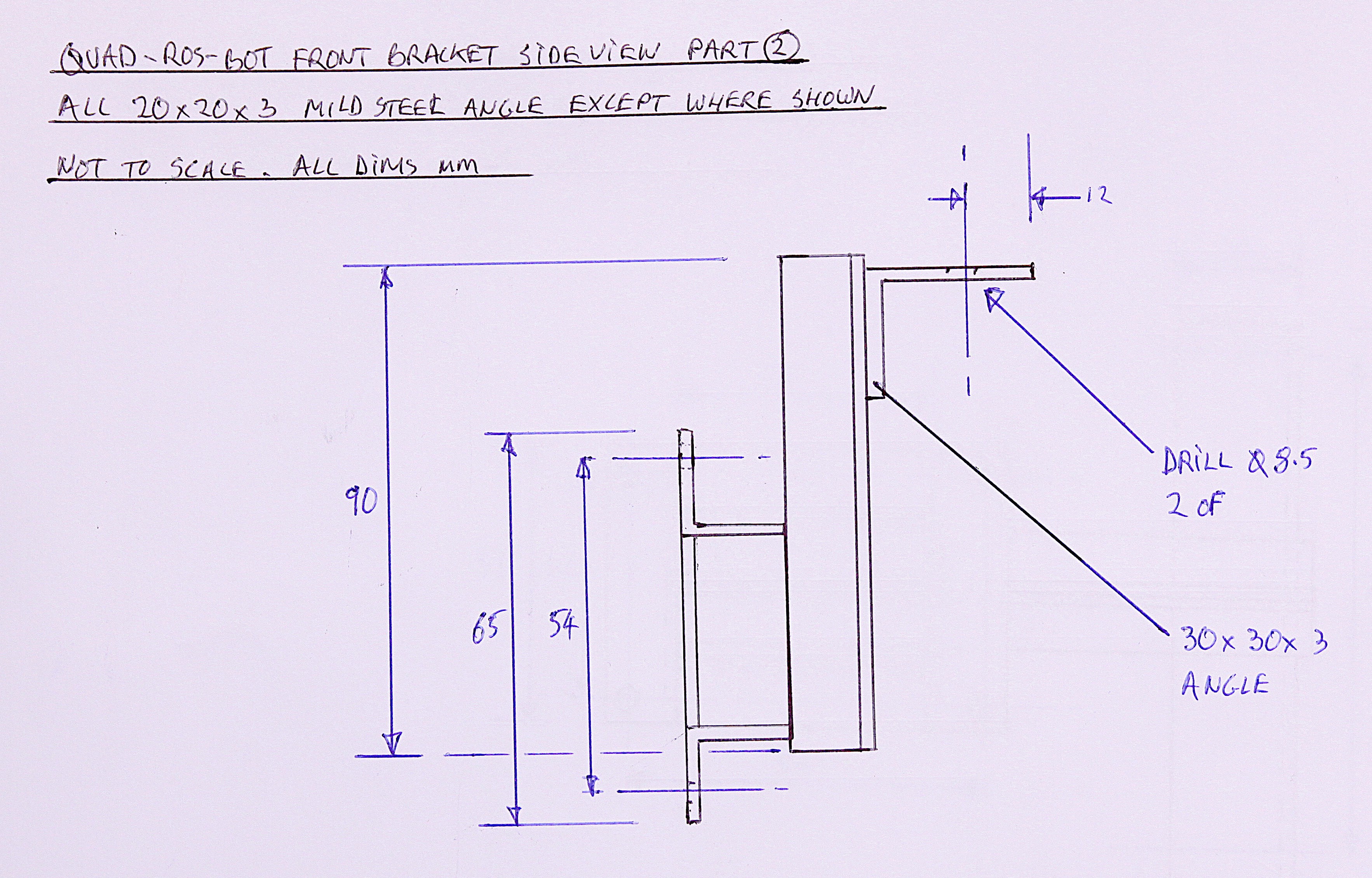
This strange looking frame goes at the very front of the robot and performs two important functions. One is to mount a load of the sensors and antennae for the control system, and the other to mount an everyday 10K potentiometer to measure the steering angle. The steering angle is NOT measured by bolting the pot directly onto the top of the steering column , but via a gearing reduction timing belt to make better use of the pot's range and hence better resolution. This also has the benefit of hiding the pot deep within the frame work, well out of harms way. Video 3:All the photos and drawings needed to build the sub frame and bracket are given in this step, below. The important thing is to present the potentiometer assembly exactly parallel to the steering column or else the whole thing will fail and the belt might also come off the timing cogs. To prevent play, or backlash, the belt needs to be fairly tight, so the welding needs to be strong. The belt also needs some adjustment and this is enabled by the series of parallel holes drilled in the angle as seen in the photo above. Slots would also be a good option if a milling machine is available.
The pot range and resolution was tested by using the Arduino Uno code below and we managed to get 340 units across the whole steering range, which is thought to be more than adequate. This could be further improved by using a gear ratio of 1:4 instead of 1:2.
![]()
![]()
![]()
![]()
![]()
![]()
![]()
![]()
![]()
Code for testing the potentiometer:
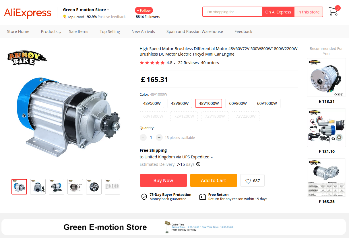
int sensorPin = A0;
int ledPin = 13;
int sensorValue = 0;

void setup()
{
  Serial.begin(9600);
  pinMode(ledPin, OUTPUT);
}

void loop()
{
  sensorValue = analogRead(sensorPin);
  Serial.print("Pot value (0 to 1024):  ");
  Serial.println(sensorValue);
  digitalWrite(ledPin, HIGH);
  delay(250);
  digitalWrite(ledPin, LOW);
  delay(250);
}
As previously mentioned, the original motor on the quad bike was no good, so we took a bit of a risk on Ali Express and bought the best looking motor than could be found that looked about the right size to fit on the bike. When it arrived we knew instantly that it was going to cure the torque problem, but fitting it into the space available might be a problem. In the event, the whole rear swing arm had to be disassembled with a hack saw and welded back together to accommodate the bigger motor.
The motor chosen for the upgrade was a 3 phase 48 V DC motor with a 5:1 planetary gearbox that could be slotted into the robot without too much modification of the rear suspension sub frame. It's always a big risk buying motors from China and when it arrived the aluminum mountings were bent out of shape like it had fallen off a conveyor belt somewhere.
![]()
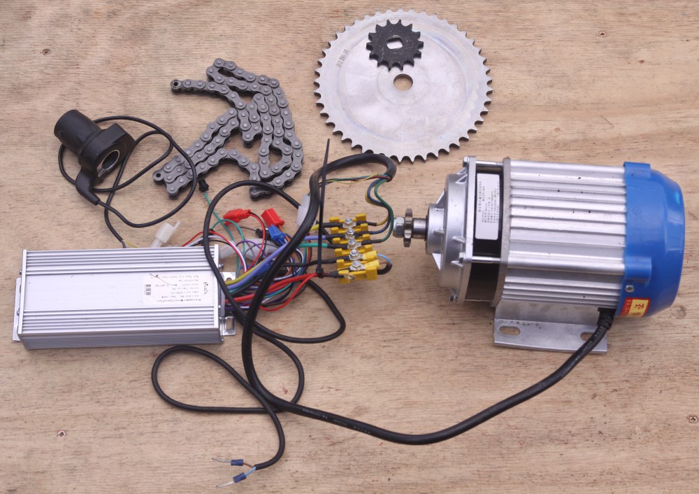
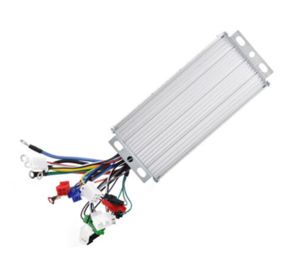
Fortunately, all went well as the mountings just bent back into shape once it was bolted onto the steel subframe. Other parts required were a 3 phase sine wave controller and some gear sprockets:
![]()
The sprocket sizes were dictated by the absolute minimum size that could be mounted on the motor, which turned out to be 8 teeth in size and the maximum on the wheel shaft without causing ground clearance problems, 48 teeth. The chain is a standard 1/2" pitch. The large sprocket was taken to a machine shop to have the center hole widened slightly and the small sprocket was ground and filed by hand to get it to fit the motor shaft.
![]()
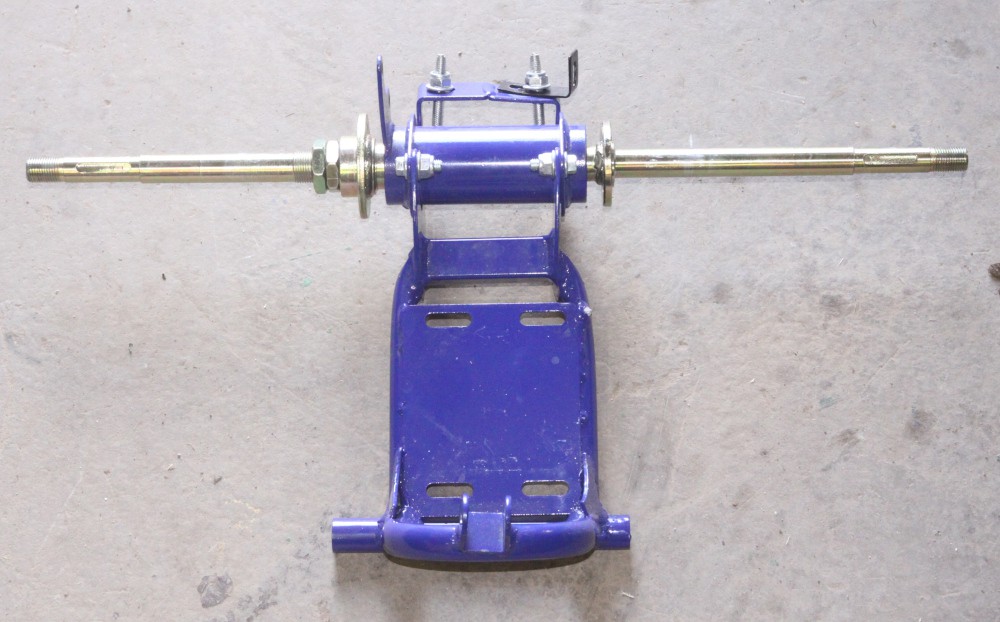
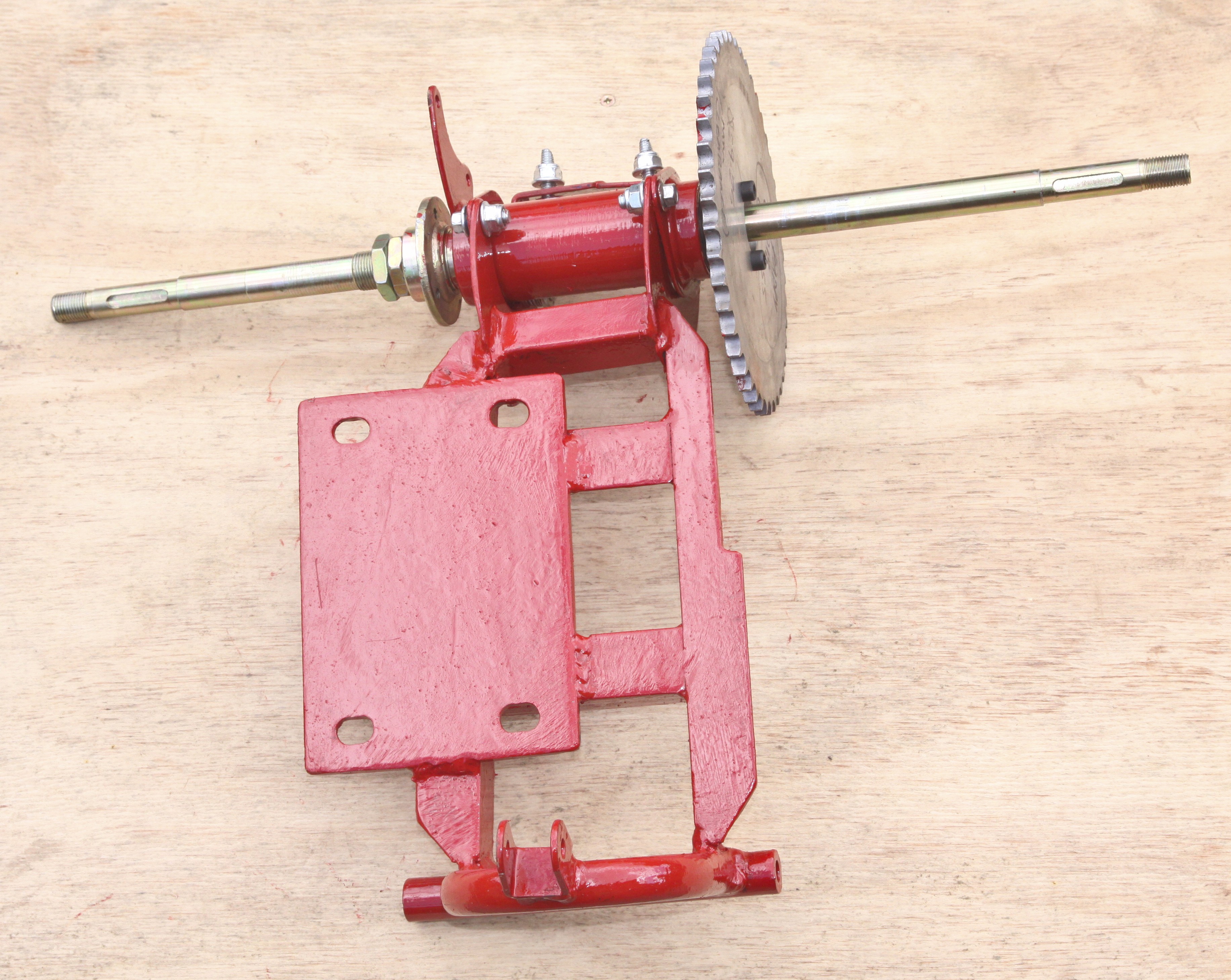
The rear suspension subframe was then removed:
![]()
This subframe was then completely rebuilt, recycling the top and bottom bearing systems:
![]()
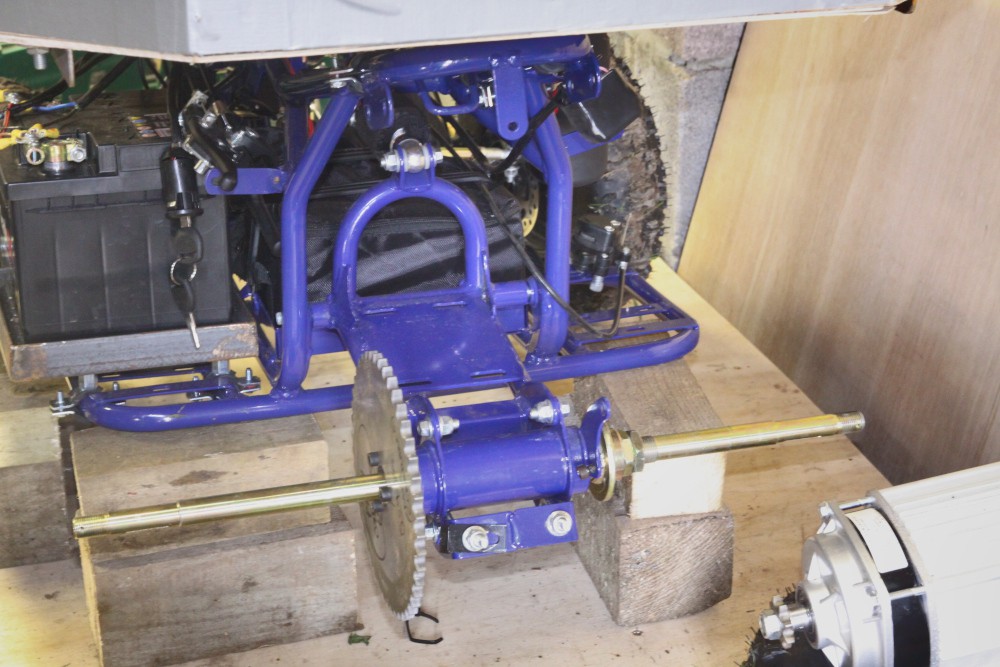
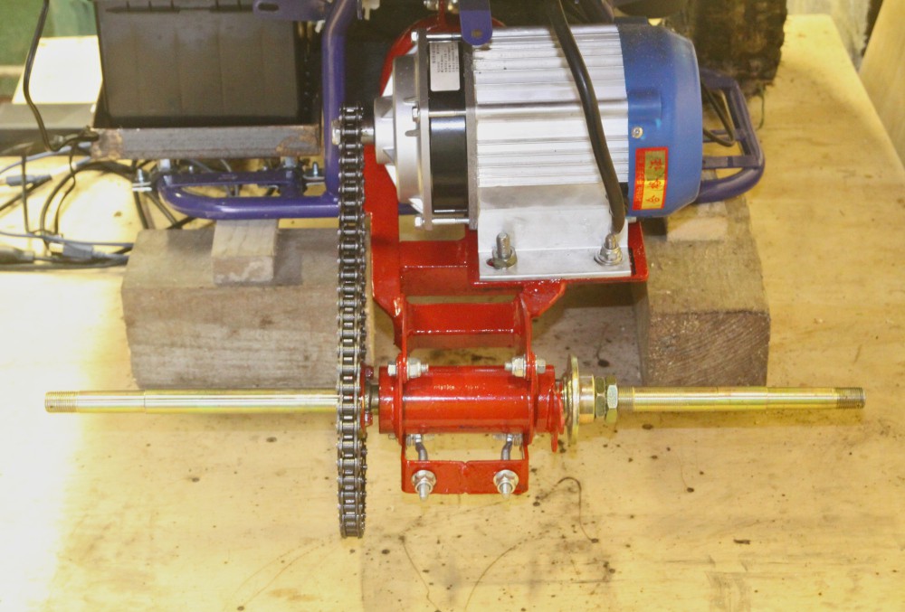
Then slotted back into the main frame with the new motor. Since the mountings are slotted, there is plenty of opportunity to adjust the motor position so that it is perfectly aligned with the main sprocket. This was done by slowly running the motor and watching / listening for errors.
![]()
At this stage the motor speed looked good - no where near as fast as the previous model. It was, however running in reverse so the outer, thick, feed wires to the motor had to be swapped around and the motor re-tuned with the two green tuning wires joined together. The motor actually came with some bask instructions and wiring diagram, which was quite useful. Now the motor could be run at full speed in forwards mode. A nice feature is that reverse is engaged digitally with a switch on one of the controller connectors rather than having to use expensive MOSFETS or heavy solenoid relays as with the old 2 phase motor.
Lastly the new motor was tested over rough ground towing a petrol lawn mower. As can be seen, it worked perfectly and did not get at all stuck like before:
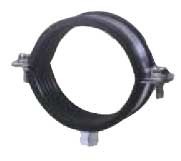
The last part in the mechanical section is just how the top coffin shaped box is fitted onto the quad bike. We used some plumbing pipe fittings that have rubber linings inbuilt:
![]()
... which fastened onto the cylindrical bike frame. Use enough of them and a nice strong sub-frame can be produced.
![]()
The image above shows the top box sub-frame (unpainted 25 mm angle). The top box itself is made of plywood and is designed to provide some protection from rain and bird poo whilst providing maximum access to the electrical / electronic components inside.
-
2Electrical / Electronics
To keep the project as simple and reproducible as possible, we tried to limit ourselves to off the shelf products as much as possible. We only used one custom built PCB to control the heavy solenoid relays for operating the steering actuator. Other than that, there is a potentiometer for sensing the steering angle and a pair of joysticks for manual control of the robot and the camera gimbal. There are a number of Raspberry Pi 4's in the project - 2 in the control room and 3 on the robot itself and one Arduino Mega on the robot. At one stage we had Intel tracking cameras on a Jetson Xavier, but removed that whole set of components due to a number of fairly nasty problems. Please refer to the logs for more info.
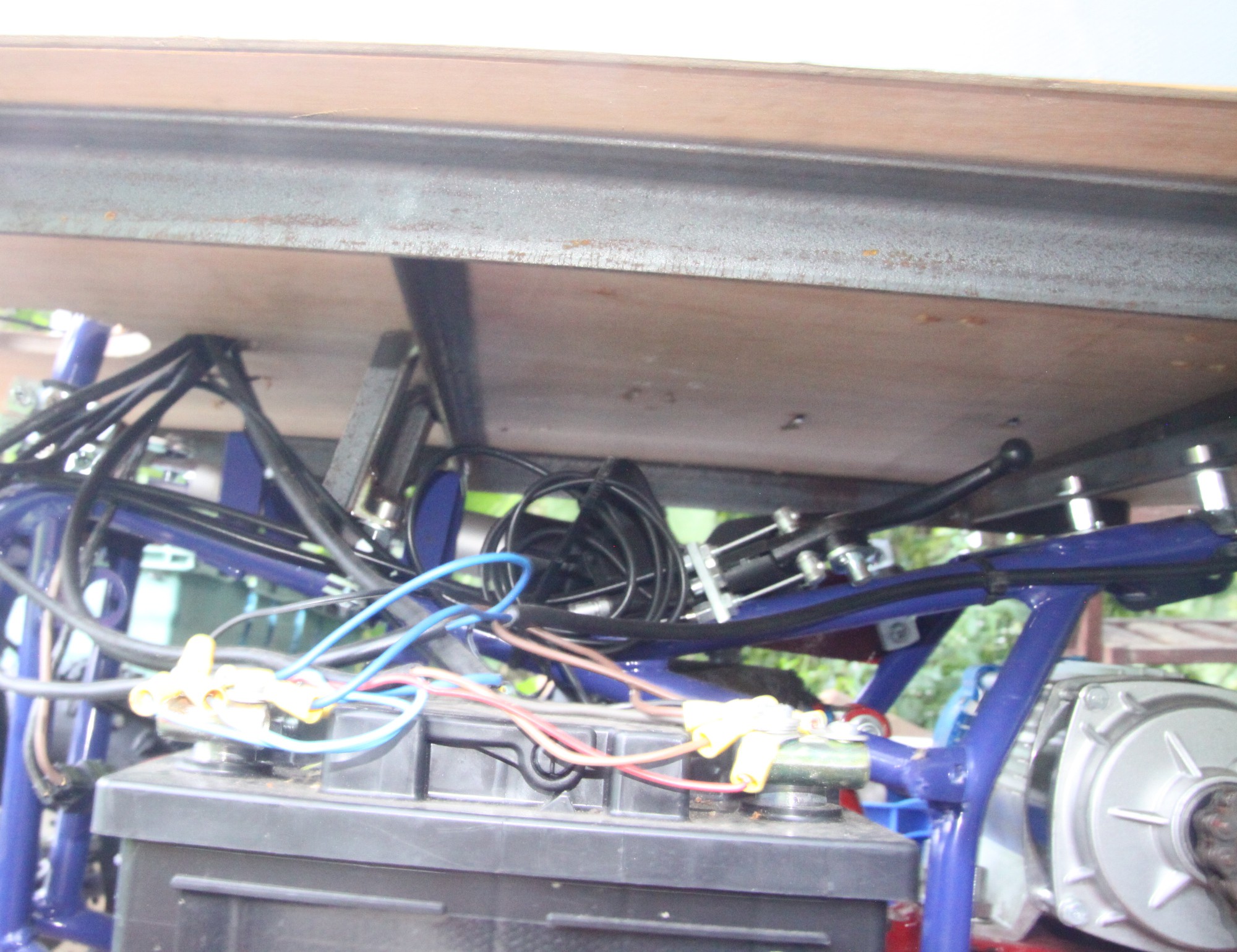
The first part of the robot that we'd want to get working is the motor itself. For safety, the robot should be chocked up so that it's wheels are off the ground before making any connections to the battery power.
![]()
The motor control box can seem quite intimidating on first glance with a multitude of coloured connections. Many of them are to enable stop lights, indicators, alarms, horn etc as the controller is a generic device designed to cover 'on the road' usage. For our robot, most of the connections are not used and we can concentrate on the throttle and main wires such as the feeds to the motor and input from the battery. Normally, the control box comes with instructions, which are normally slightly wrong ! The throttle connector requires 3 connections, one to +5v, one to ground and one to signal, which will between about 2 and 4.5 volts and it's vitally important to get these connects done properly. Since the motor is 3 phase, there will be 3 heavy cables of different colours for the motor. There should be one heavy red cable for the 36 / 48 v input from the battery and one heavy ground cable. There will be one lighter weight red cable to be connected to the on off switch which then goes to the 36 / 48 v battery supply. Lastly, there are two 'intelligence' wires to connect together during initial power up so that the controller can detect the different phases of the motor and these can be dis-connected after the motor works properly. Our controller also had a forward and reverse connector. To take up the least amount of space possible, we mounted this box in an upright position within the main top box. For a development robot, non of the electric / electronics components should be buried or hidden underneath fixed panels - everything needs to be easily accessible.
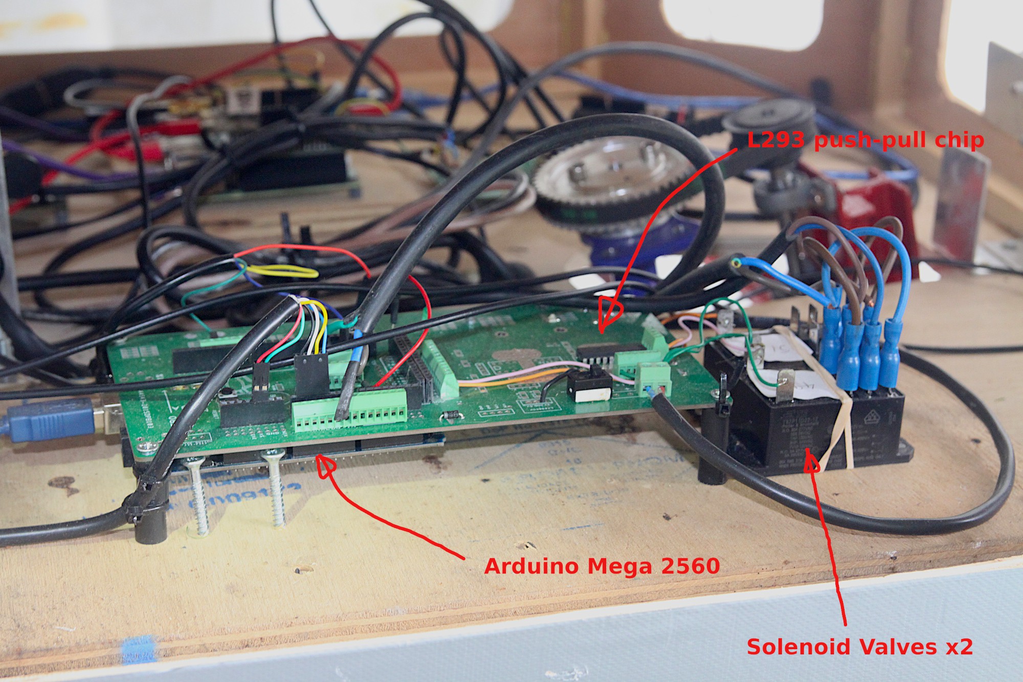
The steering control board PCB enables a low current, low voltage Arduino Mega to control a high current, medium voltage set of solenoids which need to have both a forward and reverse capability.
![]() The L293 chip, shown above, is used to step up the current and voltage for the solenoid valves, shown below.
The L293 chip, shown above, is used to step up the current and voltage for the solenoid valves, shown below.![]()
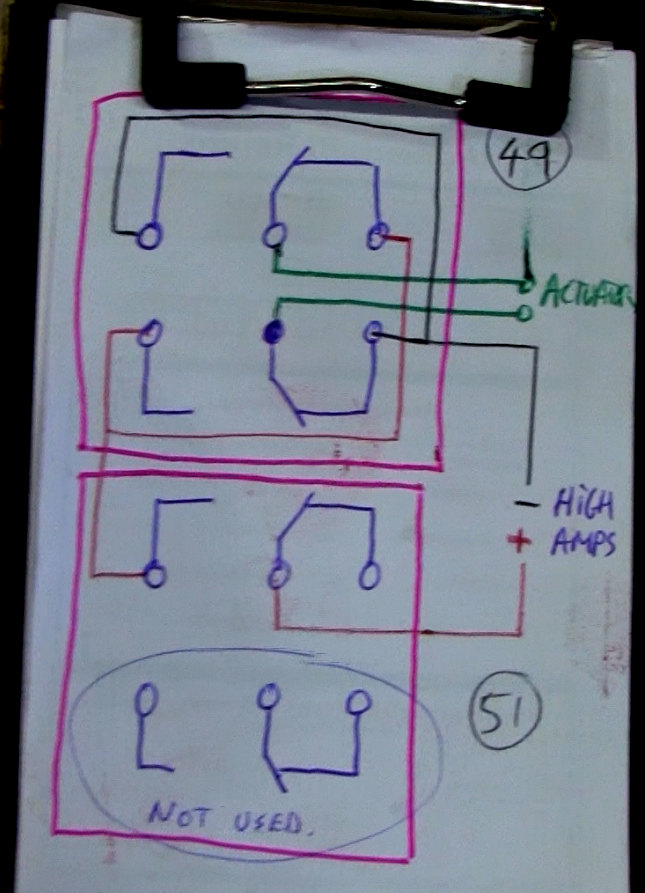
The valves need to be wired in such a way as to allow forward and reverse, so one valve does this function and the other does the on / off, using the circuit below:
![]()
'High Amps' means 12v supply direct from the auxiliary 12 volt battery. '49' is the digital pin on the Mega that swaps forwards and reverse and '51' is for on / off. Below is a snippet of the code on the Mega that controls the solenoids:
    if ((steerControlVal > 300)&&(steerControlVal < 750)) // Deadzone is set to between 300 and 750.
    {
      digitalWrite(49, LOW);
      delay(50);
      digitalWrite(51, LOW);    // Stop the actuator
    }

    if (steerControlVal > 750)
    {
      digitalWrite(49, HIGH);    // Turn right
      delay(50);
      digitalWrite(51, HIGH);    // Move the actuator
    }

    if (steerControlVal < 300)
    {
      digitalWrite(49, LOW);     // Turn left
      delay(50);
      digitalWrite(51, HIGH);    // Move the actuator
    }
The full code for the Mega is located at: https://github.com/paddygoat/Quad-ROS-Bot-MCUs and apart from the steering, contains other code for the throttle, blinking some LEDs and a ROS node. The ROS nodes will be talked about in the 'Software' section of the instructions and we've taken great pride in simplifying the nodes in the system so that they are easy to understand and use.
-
3Control System
The robot has a distributed brain composed of different MCUs and SBCs (micro-controllers and small board computers) which need to be able to communicate with each other at high speed and with low latency. In a previous robot, we designed the internal comms system from scratch and had it running on the I2C bus of the different components, but this time we thought we'd explore using a purpose built system called ROS (Robot Operating System). One thing that ROS is not is an operating system, which is a bit strange and miss-leading. An operating system is something like Windows or Linux or IOS and ROS is more like a data communication system.
When we started looking at ROS, there were a number of good tutorials for getting started with Arduinos, which were very useful. There are also a huge number of libraries for doing different functions and these seem to be heavily mechanical platform orientated so if we did not actually own a Turtlebot, they seemed to be largely irrelevant. We decided very early on to start writing our own nodes for ROS is Python and in retrospect, this was undoubtedly the easiest and most effective way forwards.
Python is a interpreted language so it does not normally need manual compiling but when using a Python node in ROS, it needs to be plumbed into a complete entity using a build system called 'Catkin'. Here is an example of a typical build procedure:
https://github.com/ros-agriculture/ublox_f9p.git
source /opt/ros/melodic/setup.bash
cd ~/catkin_ws/src/
git clone https://github.com/ros-agriculture/ublox_f9p.git
cd ublox_f9p/
git checkout `git tag | sort -V | grep -P "^2.\d+\.\d+" | tail -1`
cd ..
catkin_init_workspace
cd ..
catkin_make clean
catkin_make -DCATKIN_ENABLE_TESTING=False -DCMAKE_BUILD_TYPE=Release
catkin_make install
A re-occurring theme in ROS is the need to specify the source ie
source /opt/ros/melodic/setup.bash..... but this is all covered in the ROS tutorials, so beyond the scope of these instructions.
To add a new python node, the Catkin build system must be activated, but once the node is in place, it can be edited at will. The best way to start is to get Arduinos blinking from a Linux PC and then work up to adding a python node. Use one of our Python nodes as a template! eg. https://github.com/paddygoat/joystick/blob/main/joystick.py ... which is a very simple but effective example.
The key to building a ROS communications system is experimentation. Start with a simple set up and then add nodes to it. The Python scripts need to be located in the correct folder for Catkin to incorporate them eg
~/catkin_ws/src/..... and have fun!
Basic Farm Robot 2021
Minimal 'no frills' development platform for farm robots


 The L293 chip, shown above, is used to step up the current and voltage for the solenoid valves, shown below.
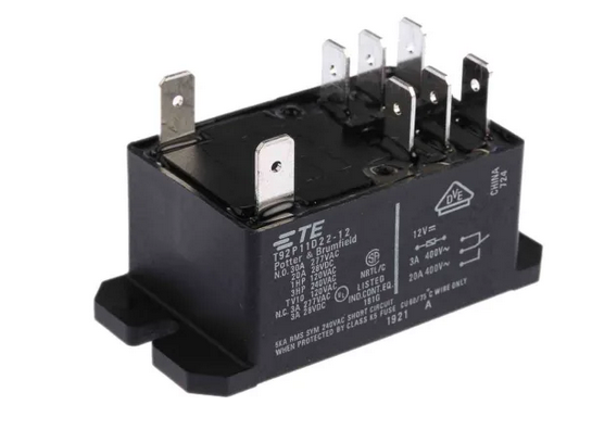
Discussions
Become a Hackaday.io Member
Create an account to leave a comment. Already have an account? Log In.