The main idea of the project was to create a wireless network of sensors and actuators (grouped into arbitrary nodes) for data acquisition and control in the automated greenhouse. Although initially it was intended to be used in a hydroponics greenhouse the project is made with adaptability in mind so that it could be used in most cases where small-scale automation is required. All data is collected from sensors and sent to the gateway node connected to web server, where processing of the obtained information takes place. Commands to actuators follow the same route in the opposite direction. This structure allows flexible and versatile solution for automation with modular approach that can be deployed quickly to any greenhouse.
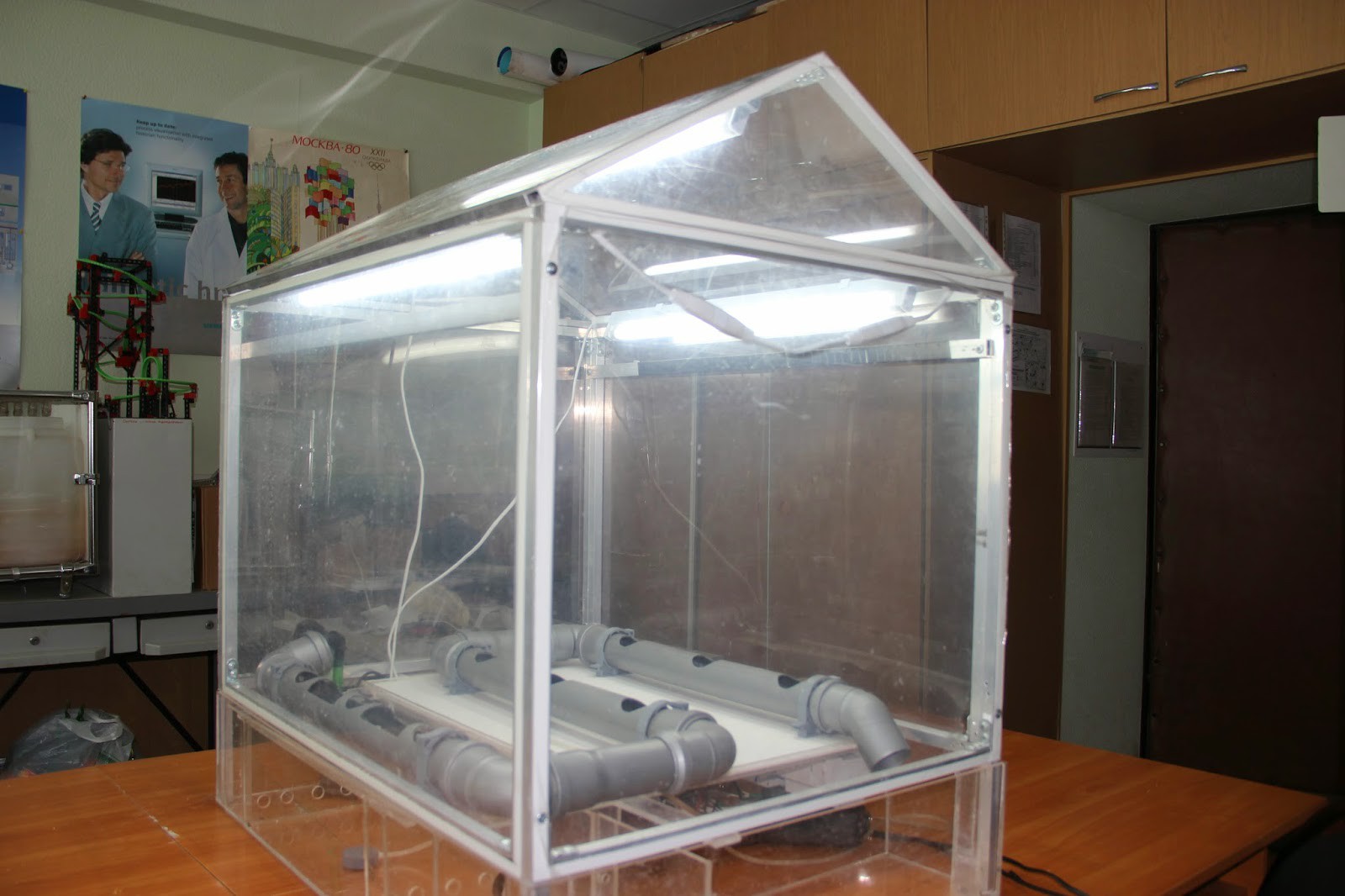
A place to deploy the system was fortunately found in my own university, where senior students built a hydroponics greenhouse to test various automation solutions (if memory serves me, the last thing that ran this greenhouse was PLC).
The general diagram of the network that I've devised is shown in the figure below:
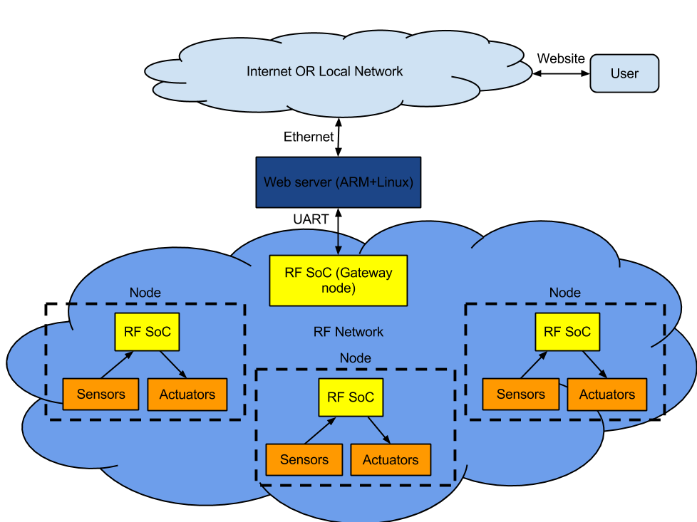
Each sensor/actuator is equipped with a microcontroller that uniquely identifies this sensor in I2C network and allows the user to easily plug them to nodes in any order and any quantity (not exceeding the I2C address space size, obviously). The bidirectional link is established via radio with the gateway node, which sends the commands to nodes and receives data from sensors relaying it to the server. The server could be any single-board computer (like Rappberry Pi) or even an actual PC running the application which handles the link to gateway node.
Each node is equipped with CC430F5137 RF SoC, which is responsible for RF link between the nodes and connection to I2C network of nodes. Frequency was chosen to be 433MHz, that is, an unlicensed frequency for ITU Region 1. The schematics of each node is shown below:
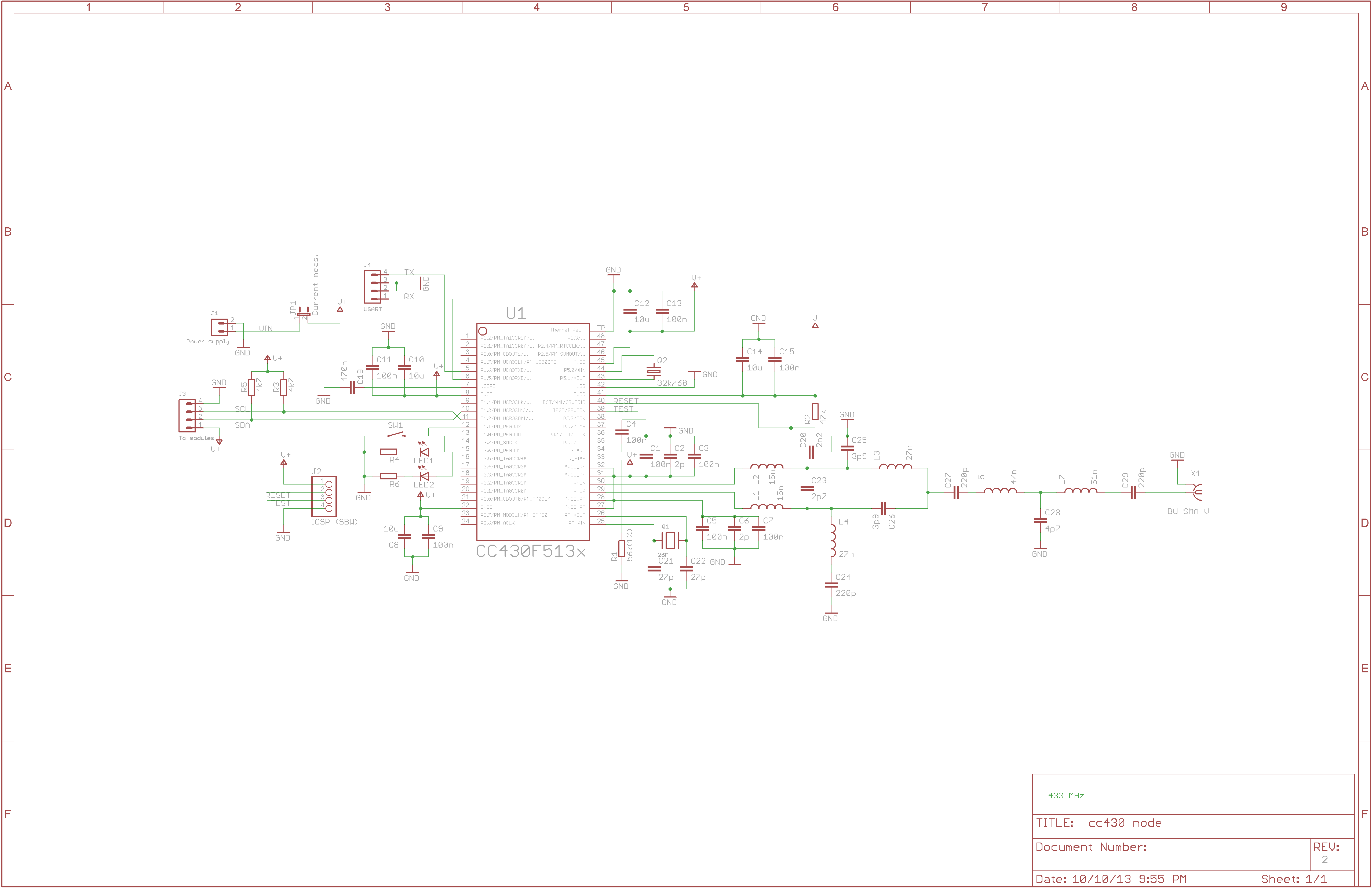
The balun circuit was taken from TI app notes and is designed specifically for reception and transmission of 433MHz radio waves. Programming of the board is done via Spy Bi-Wire interface (J2) inherent to all microcontrollers of MSP430 series. J3 connects the node to its sensors and actuators (you'll see later how a bus connection allows to use only one connector to join virtually unlimited number of sensors/actuators).
Each sensor/actuator module is comprised of MSP430G2230 uC and the sensing element itself. The sensors chosen are all cheap and widespread, at the cost of low precision. Most amateur projects and greenhouses in general don't need high precision anyway (plants are supposed to be resisient to changes in temperature within +/- 5 degrees). Figures 5 to 8 are the schematics of sensor/actuator modules already implemented:
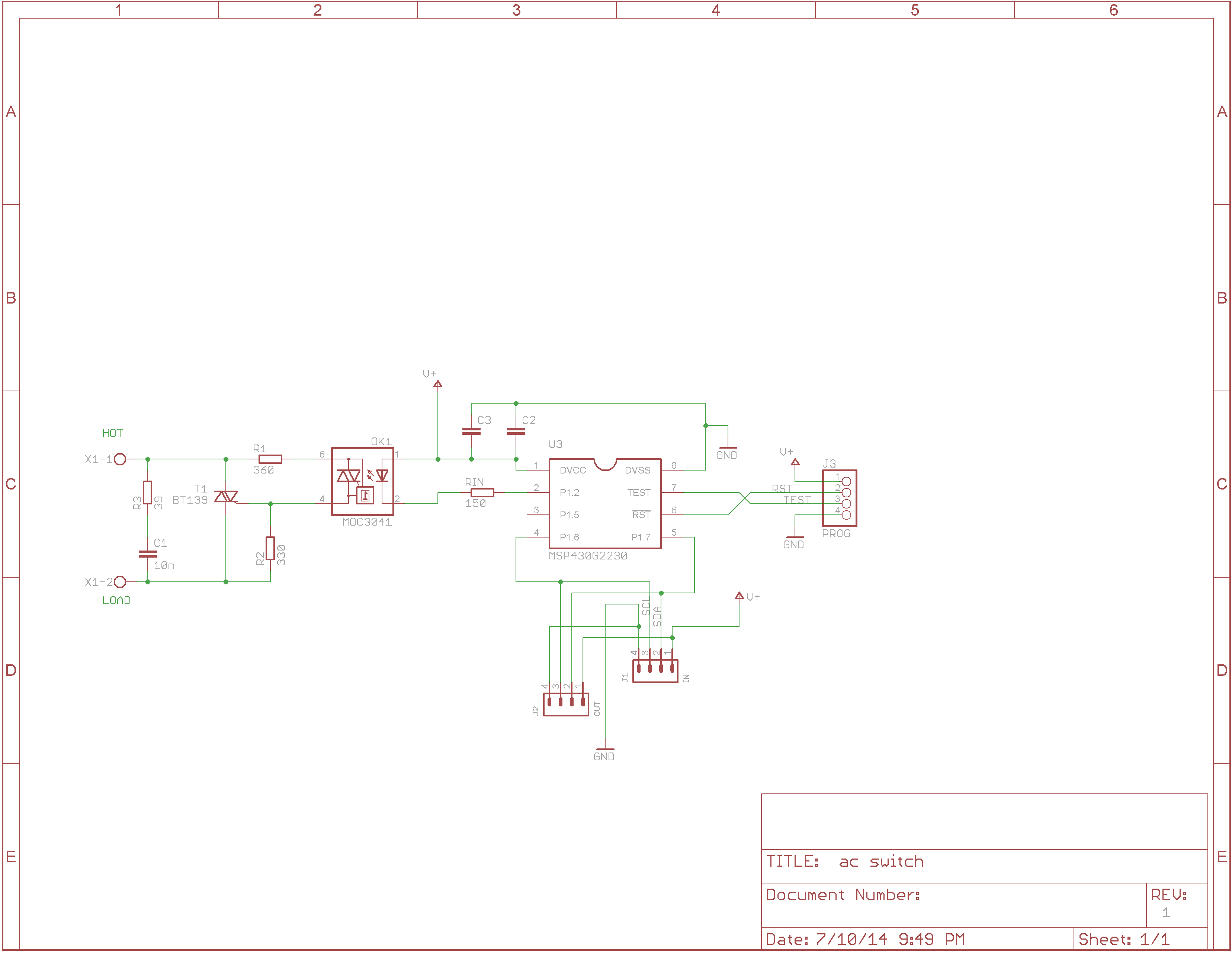
Mains switching module (BT139 TRIAC + MOC3041 driver).
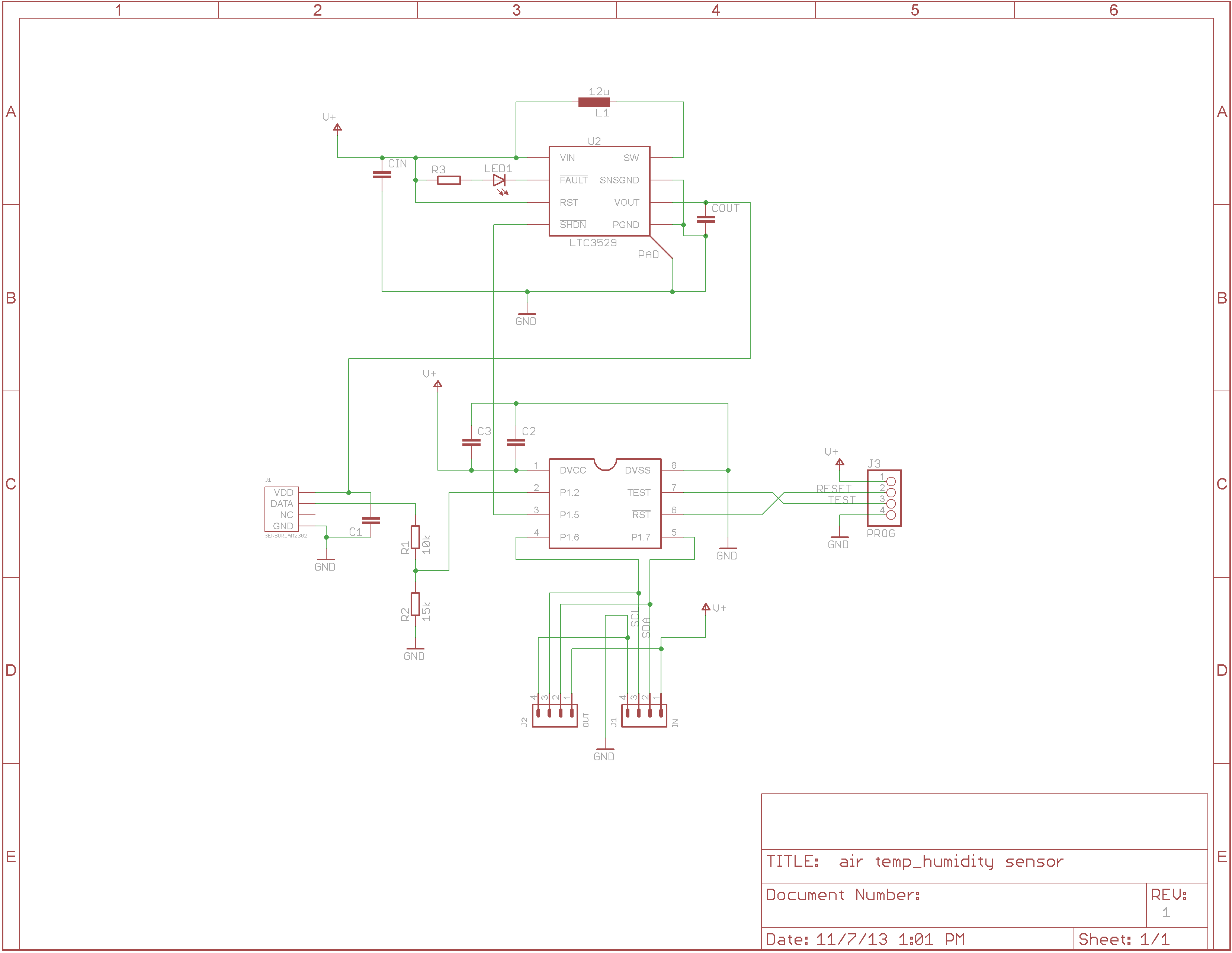
Air temperature and humidity sensor (DHT22).
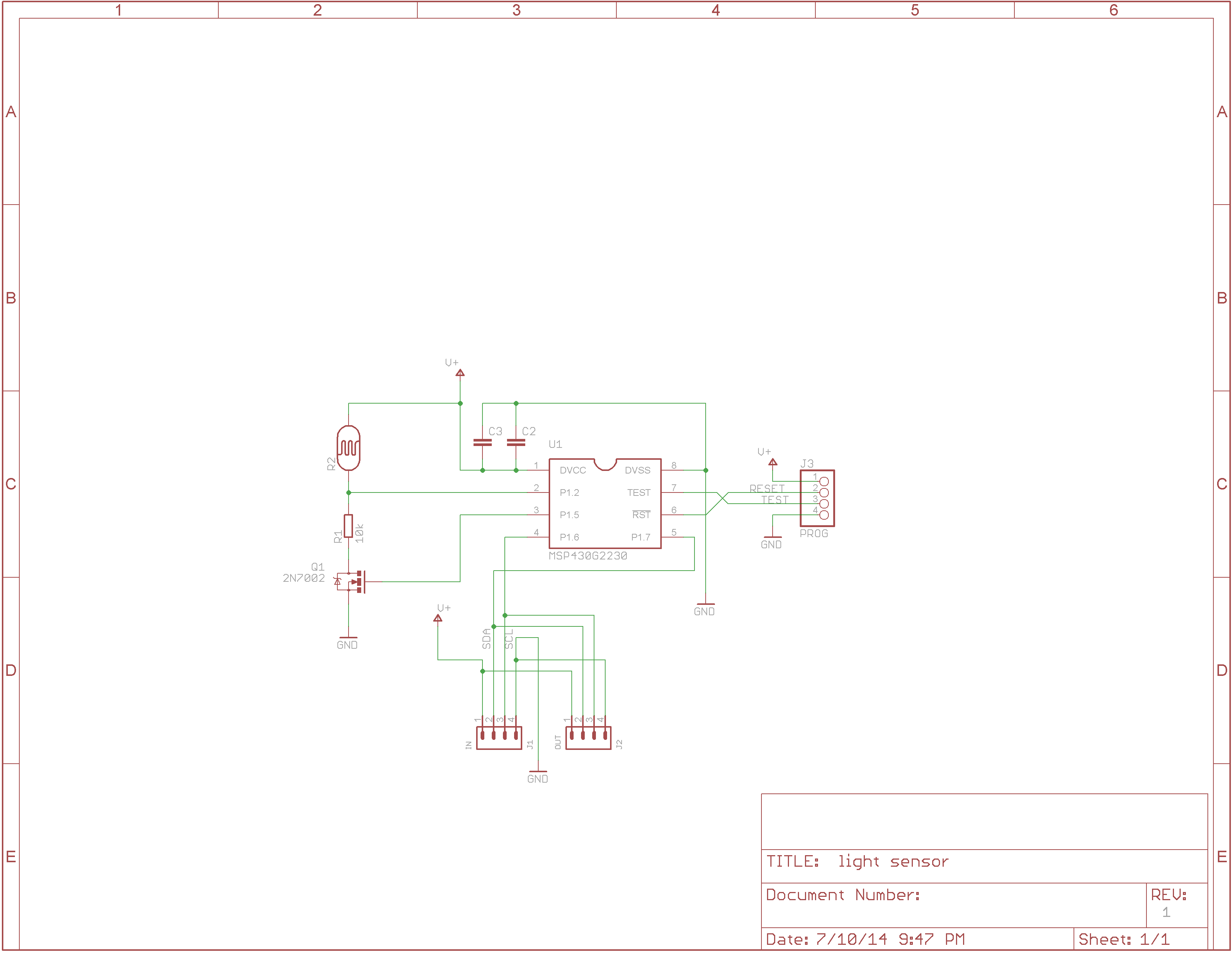
Light intensity sensor (Merely a CdS photoresistor).
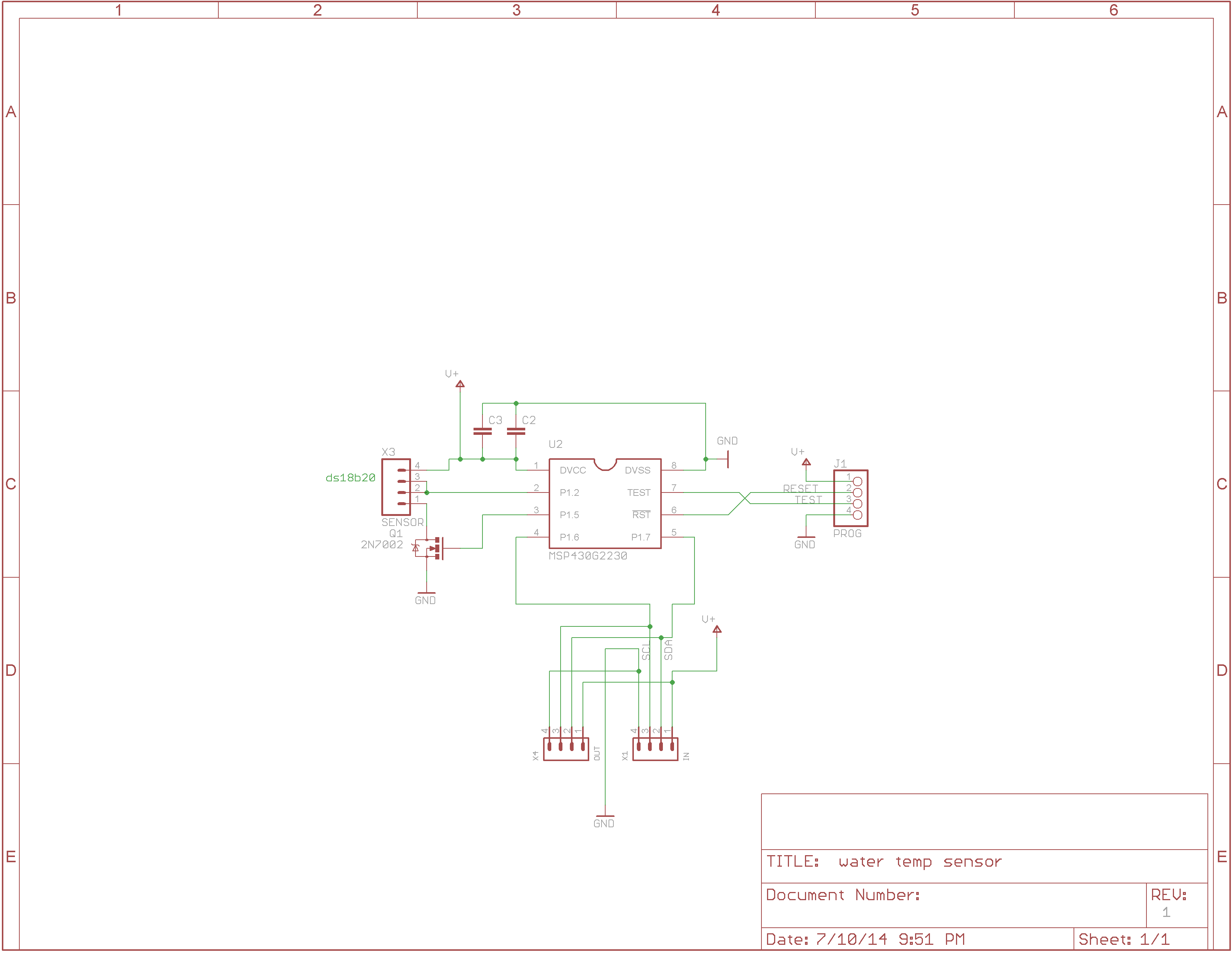
Water temperature sensor (DS18B20 in waterproof enclosure).
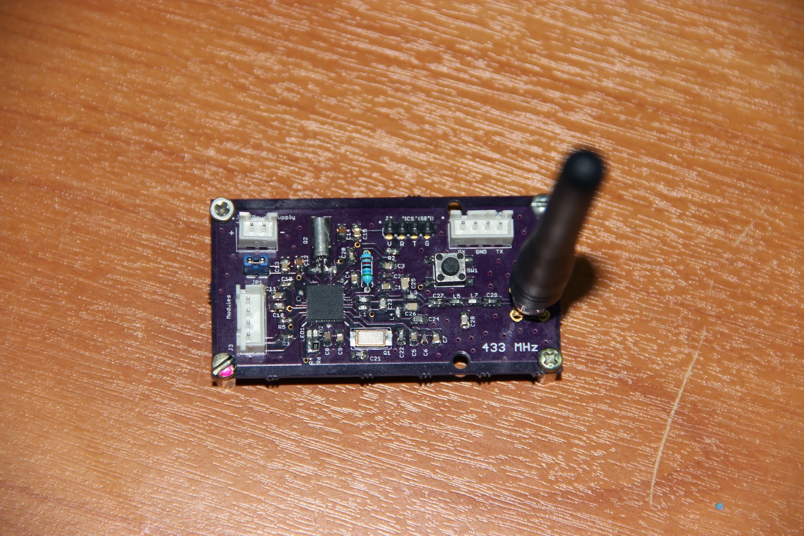
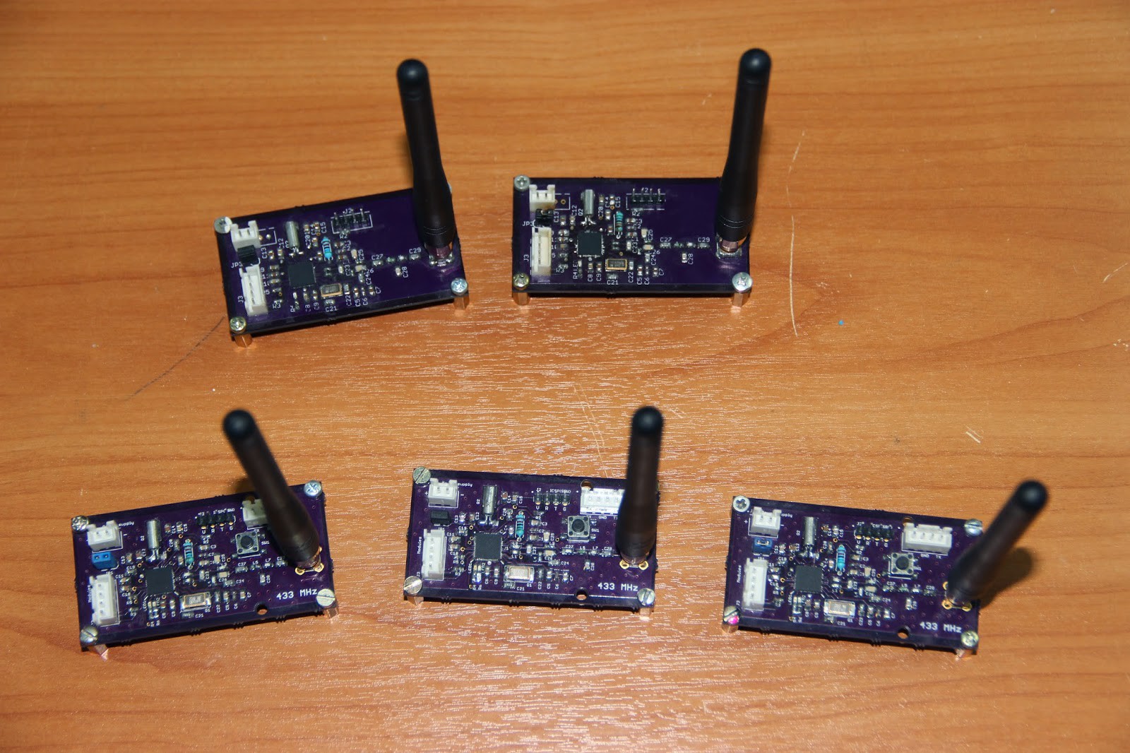
Here are some pictures of assembled PCBs:
Physical manifestation of a WSN node.
Even more of them!
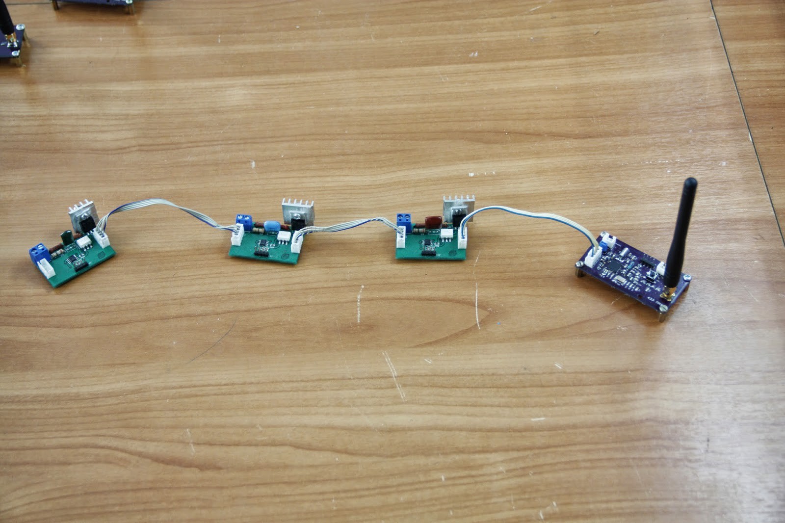
Node connected to mains swithing modules
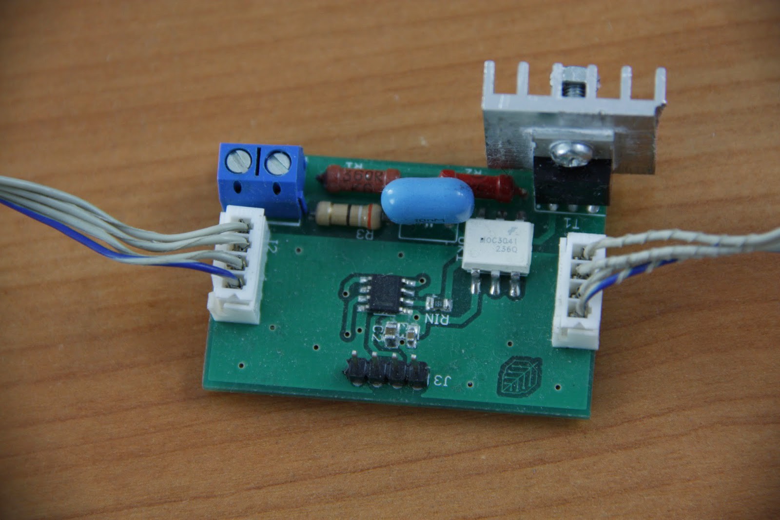
Mains switch (BT139 TRIAC + MOC3041)
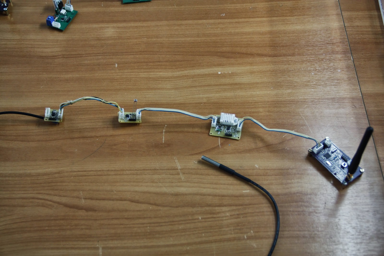
Left to right: water temp. module (with the sensor sticking from below), light int. sensor, air temp. and humidity sensor.
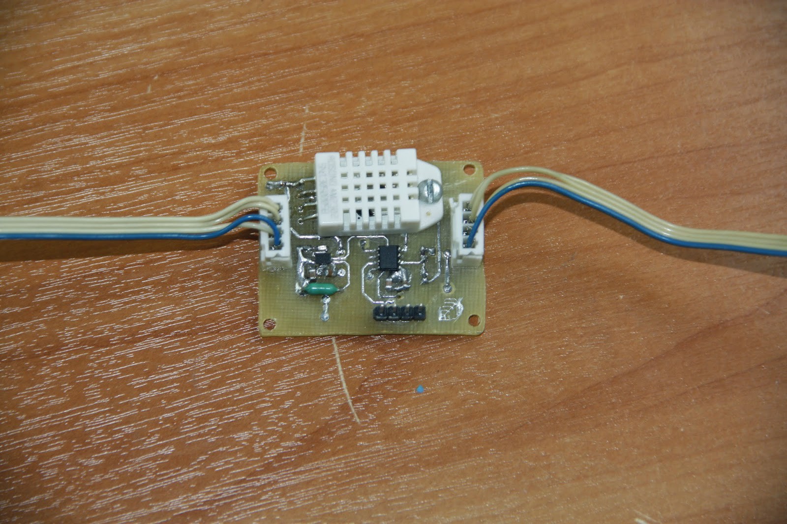
Air temperature and humidity sensor (DHT22).
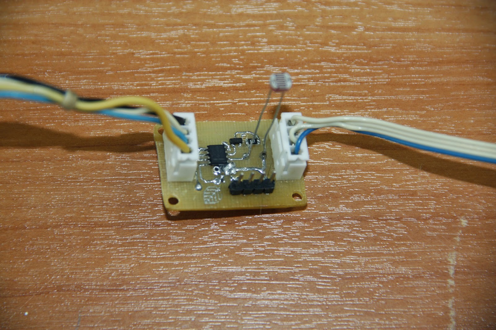
Light intensity sensor (CdS photocell).
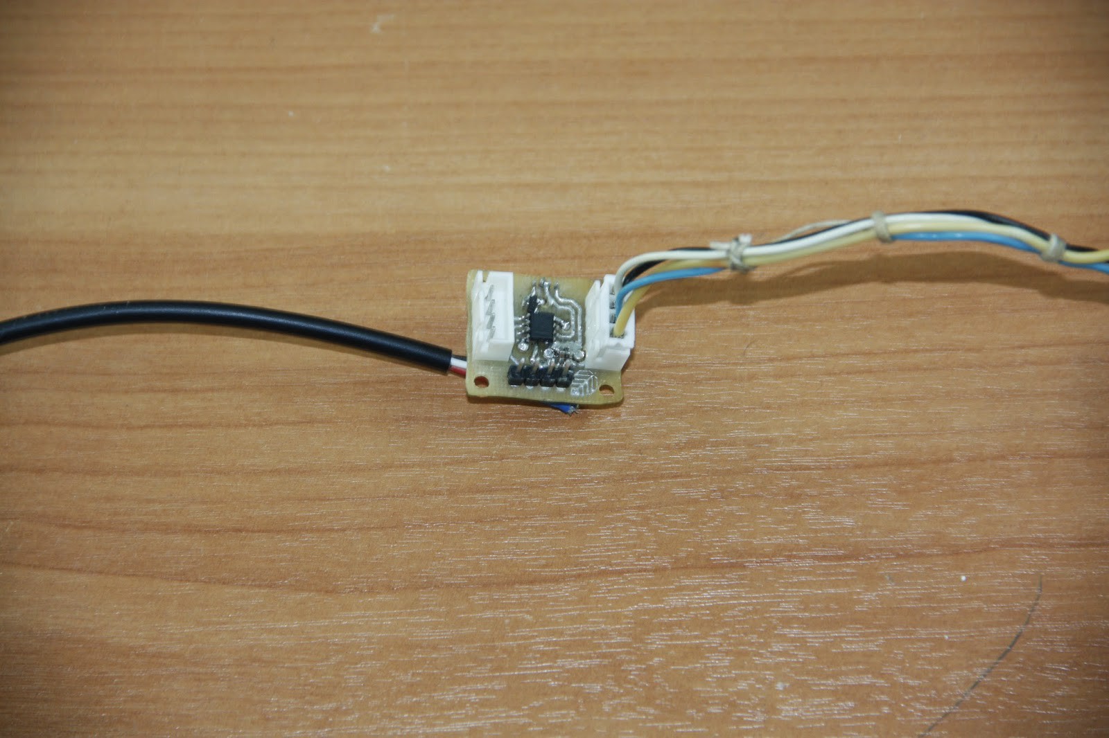
Water temperature sensor (DS18B20).
 panovvv


 Guy Cole
 Makerfabs
 Mario Frei
Great & interesting to me as an aficionado.
I'm keen to start my first simple project, a automatic sprout maker, with temperature, humidity control/regulation; water sprinkler, seasonal setting storage & that can also have flexibility to get further programmed as a yogurt maker or egg incubator...
Hope to get applied ideas from experts pool @Hackaday.io. It will definitely be a boost for a novice to stay on the path.