 New Dexterity
-
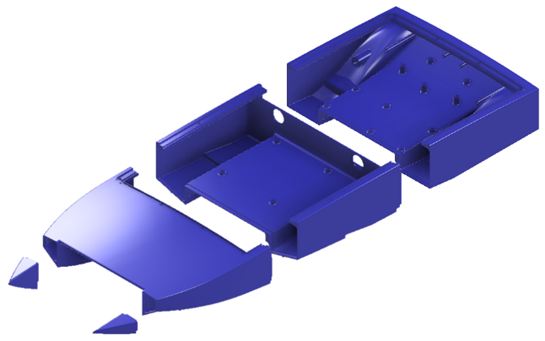
13D Print Hull
It will be four separate prints using a Prusa mk2 I3 with a print bed size of 250*210*210mm. The filament used is just PLA with the infill at 20% and the layer height at 0.2mm.
-
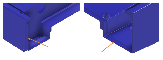
2Bonding the Hull
Once they are all printed they can be bonded together using 5 minute epoxy on the male/female joints.
-
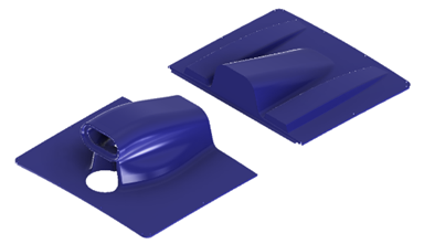
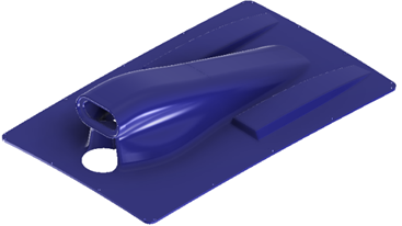
33D Print Hull Cover
This is made up of two pieces and uses the same print setting as before. Once printed it can be bonded using 5-minute epoxy as well.
-
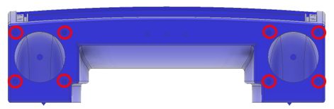
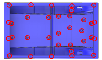
4Threaded Inserts
SM3 inserts for 3D printed parts are used almost everywhere. They can be inserted using a soldering iron on low heat. Red circles highlight where to put them.
-
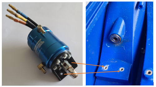
5Motor Mounting
If you select a different motor you will just need to modify the mounting bracket. The bracket was attached to the motor first with 6 M3 6mm long bolts and then the coupling attached to the motor shaft using grub screws. After a bearing is pressed into the inlet the motor bracket can be inserted into the boat using two more M3 6mm bolts.
-
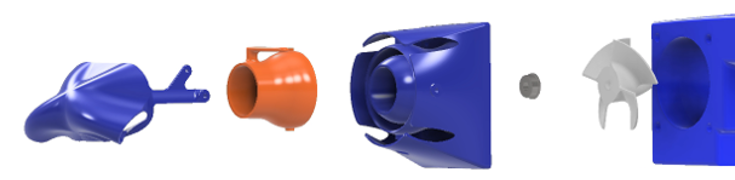
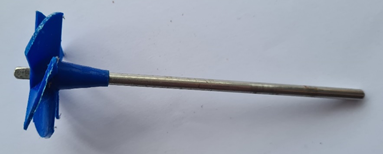
63D Print Jet Components
The impeller should be printed at 100% infill with a 0.1mm layer height. The nozzle, thrust vector and reversing bucket are printed at 40% infill with a 0.15mm layer height.
-
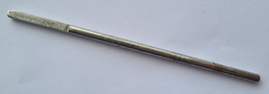
7Impeller Shaft
The shaft can be cut from a 4 mm diameter rod to a length of 120 mm and then 30 mm at one end can be filed to a depth of 1 mm for the impeller can be pressed onto. Once attached it can slide in the jet housing/inlet and be attached to the coupling on the motor shaft.
-
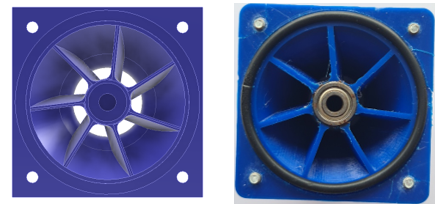
8Nozzle Preperation
Installing the nozzle requires a custom O-ring to be cut to the size of the slot. The ends of the o-ring are bonded with super glue. A bearing is press-fit into the nozzle centre. The nozzle can then be slotted over the shaft and attached with 4 M3 6 mm bolts.
-
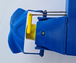
9Thrust Vectoring
Thrust vector and the bucket can now be installed with 4 M2.5 bolts. Along with the connecting rods attached to the thrust vector and bucket.
-
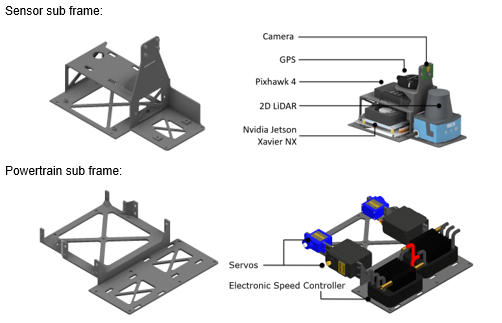
10Sensor and Powertrain Installations
These are custom to the user's hardware but the mounting holes are based on the provided geometry. The parts are simply bolted onto the subframes in the designated positions. All the components should be attached to the brackets before being installed into the boat.
Low-Cost, Waterjet-Powered Robotic Speedboats
This project focuses on the development of open-source, low-cost, waterjet-powered robotic speedboats for education and research
Discussions
Become a Hackaday.io Member
Create an account to leave a comment. Already have an account? Log In.