AIRPOCKET
-
How to adjust the paint
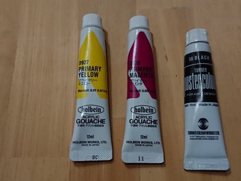
10/12/2021 at 01:29 • 0 commentsI used the following paints, but you can use any kind of watercolors.
Cyan:
holbein ACRYLIC GOUACHE D928 PRIMARY CYAN
Magenta:
holbein ACRYLIC GOUACHE D926 PRIMARY MAGENTA
Yellow:
holbein ACRYLIC GOUACHE D927 PRIMARY YELLOW
Black:
TURNER'S ACRYL GOUACHE AG020009 JET BLACK or TURNER'S poster color #58 BLACKDilute the paint in the tank about five times with water.
When thinning, use a scale to measure the paint as accurately as possible. 1.00g of paint to 4.00g of water.
The strength of the color will vary depending on the paint, so if the colors do not match well, make adjustments.
To adjust, change the dilution factor of the paint or change the factor in the Raspberry Pi PICO program.![]()
I was going to take a picture of the paints, but I can't find cyan. Could it be the work of my naughty daughter?
-
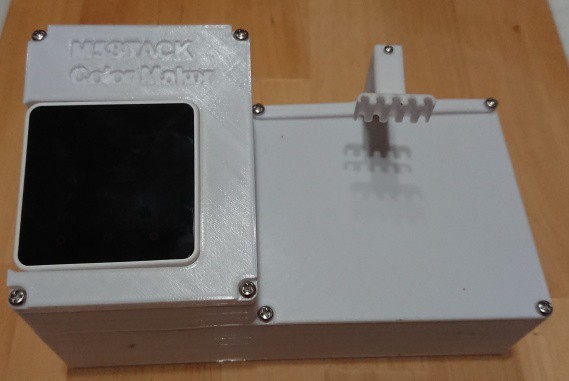
Final step of assembly
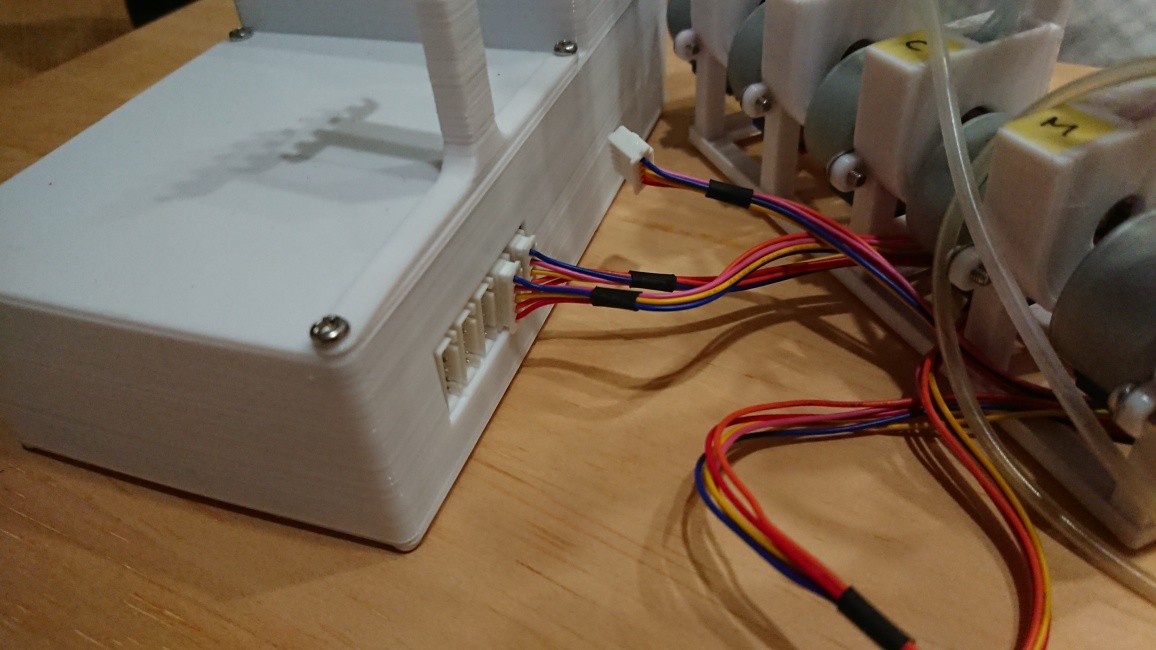
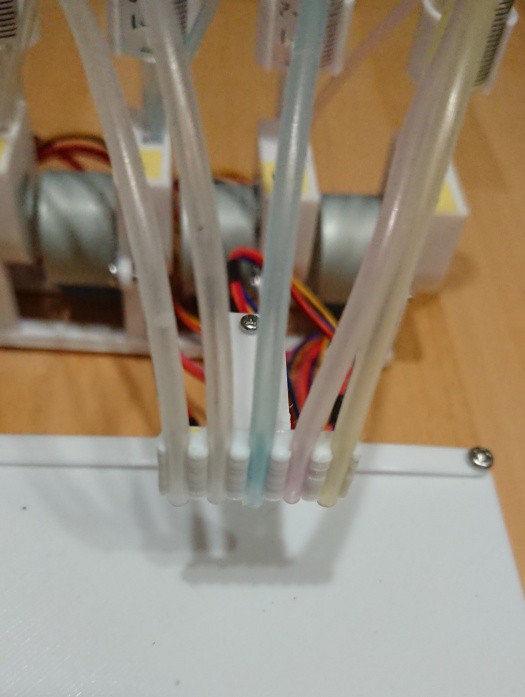
10/12/2021 at 01:04 • 0 commentsUp to this point, the main unit and the pump unit have been assembled.
The last step is to connect the main unit and the pump unit.
Connect the connector of the stepper motor to the connector of the main unit.
![]()
Attach the tube extending from the pump to the tube clamp.
![]()
The M5Stack Color Maker is now complete.
Let's test it by turning it on.
Power is provided by a USB cable connected to the M5Stack or Raspberry Pi Pico.
Since they share the same 5V USB power supply, you can just plug the cable into either one.Let's try using the SCAN and Color Make functions to see if the UI and pump work.
-
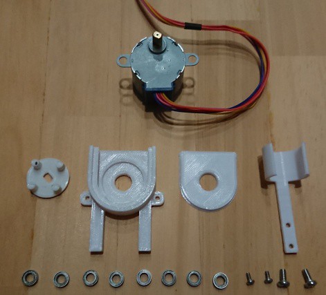
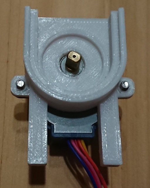
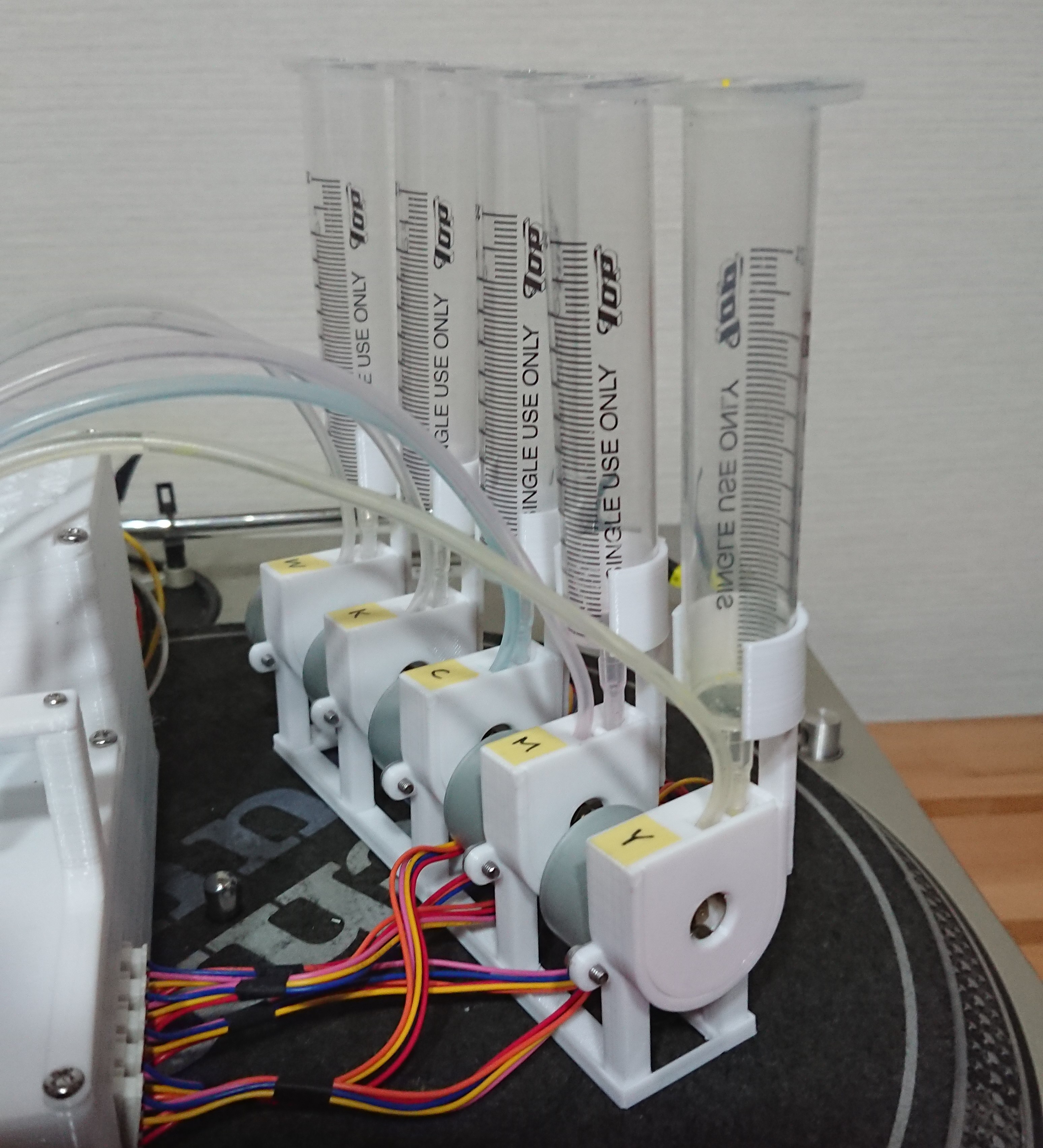
Assembly of the pump unit
10/12/2021 at 00:58 • 0 comments![]()
Attach the stepping motor to the pump case.
![]()
![]()
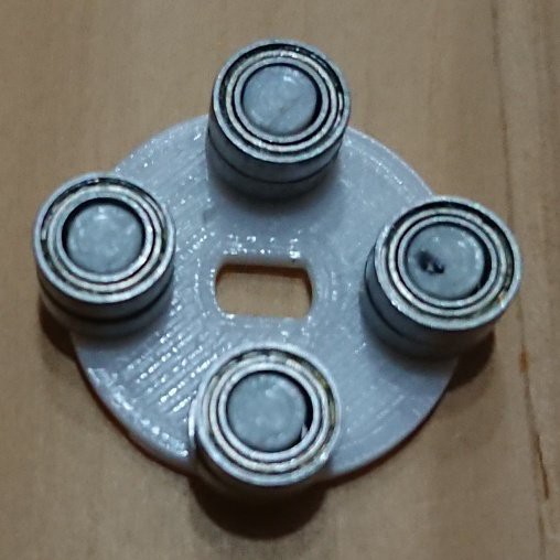
Attach the bearings to the rotor. There should be two bearings per arm of the rotor.
![]()
Attach the rotor to the shaft of the stepping motor.
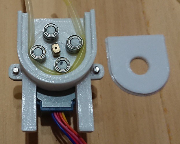
Pass the tube between the bearing and the case, and cover it with the lid.
![]()
![]()
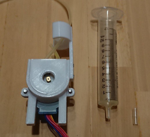
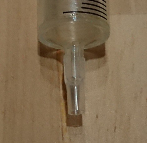
Insert the tubing into the end of the syringe. If you can't mount it directly, you can use a larger piece of tubing as a coupler.
![]()
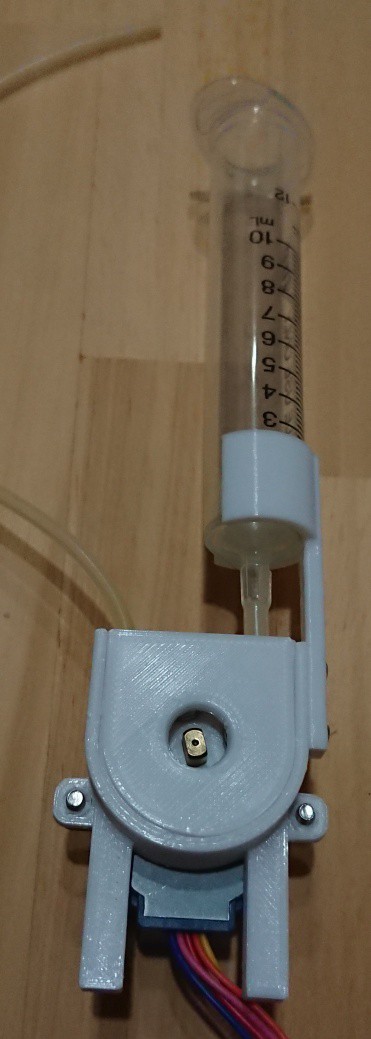
Attach the syringe bracket to the case.
![]()
Attach the pump to the base and you are done.
![]()
![]()
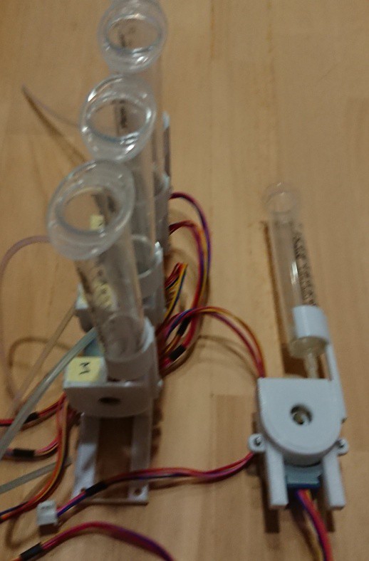
Make five identical ones and attach them to the base and you are done.
-
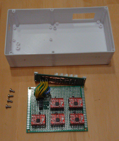
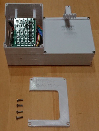
Assembly of the main unit case
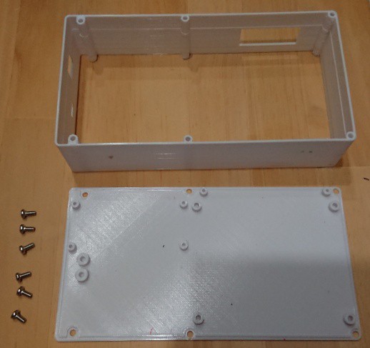
10/08/2021 at 08:48 • 0 commentsOutput all the attached parts and assemble as follows.
Fasten the Bottom and Lower case with 6 M3 screws, and attach the Motor Driver & Stepper Motor connector board.
![]()
![]()
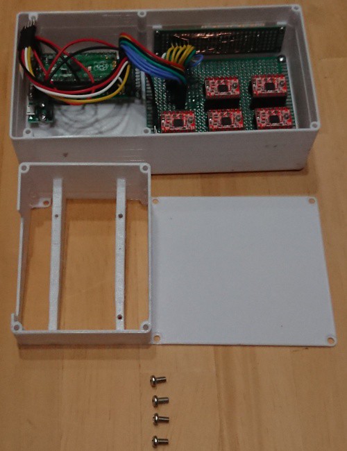
Attach the PICO to the Raspberry Pi PICO connect board and attach the board to the case.
Connect the PICO board to the driver board with the connector.
![]()
Attach the middle component of the case with four screws.
![]()
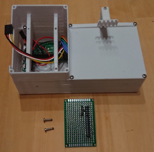
Connect the M5Stack connect board to the Raspberry connect board with the cable.
![]()
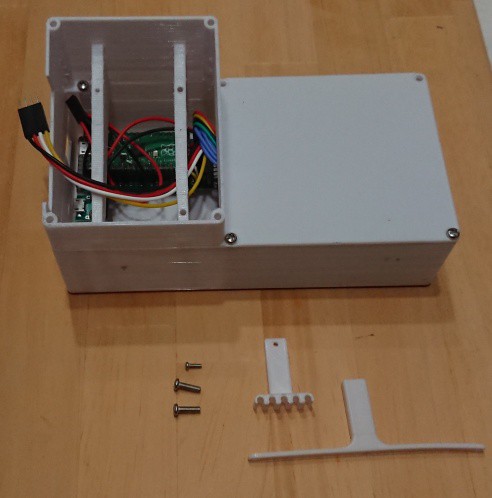
Attach the M5Stack connect board to the housing.
![]()
Screw in the tube bracket and clamp, then attach them to the housing.
![]()
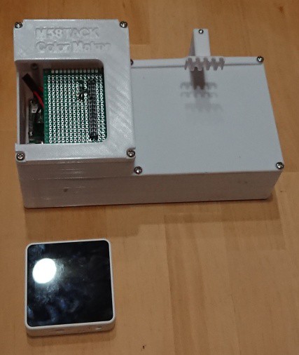
Attach the top part of the housing and insert the M5Stack into the board.
![]()
![]()
![]()
-
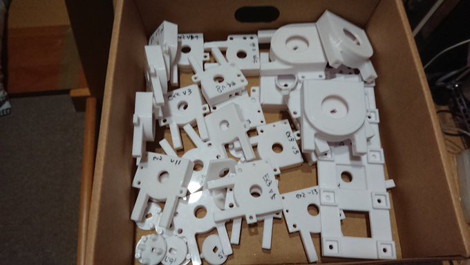
Creating 3D Printer Parts
10/08/2021 at 08:25 • 0 commentsThe device is divided into two parts:
![]()
The main body case and the pump unit. The left half of the main body case is used as the UI, while the right half holds the plates and mixes the paints.
![]()
The pump unit has five tube pumps and five syringes for the paint tanks attached to the stand. 5 tanks and pumps are used to supply water in addition to the four CMYK colors.
Watercolors use not only the paint, but also the white of the underlying construction paper to produce the color. To take advantage of the white color of the paper, water is mixed with the paint to control the transparency of the paint.The 3D printer is a Kingroon KP3S and the material used is PLA.
-
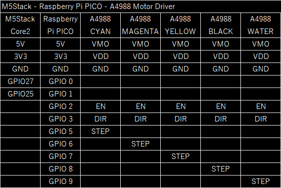
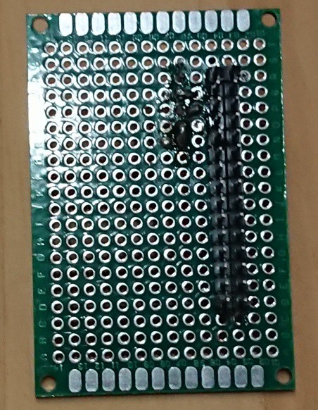
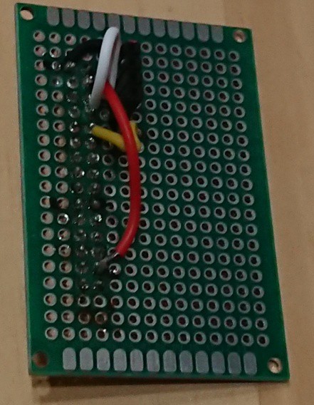
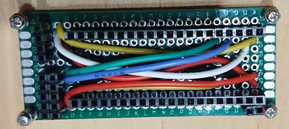
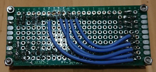
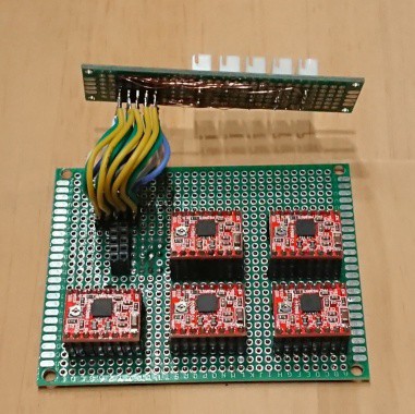
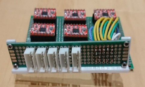
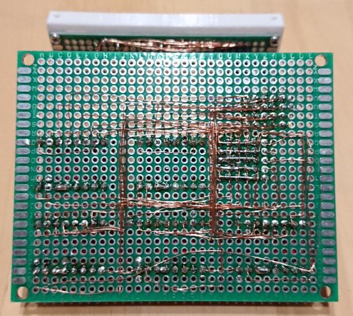
PCB Assembly
10/08/2021 at 08:04 • 0 commentsSince I do not have the skills to design boards, I created the circuit using universal PCB boards.
Although four PCBs are used, all of them are just for connecting devices, so you can use them without boards and just connect cables to each other.Here is a table showing the connections for each.
![]()
![]()
The resulting board is as follows:
1.M5Stack connect board
![]()
![]()
2.Raspberry Pi PICO connect board![]()
![]()
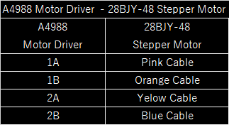
3.Motor Driver & Stepper Motor connect board![]()
![]()
![]()
I used AWG24 cable or 0.1mm UEW cable for the connections in the boards, as UEW cable does not take up much space and does not need to be removed, so it is very easy to wire once you get used to it.
-
Reducing pulsation
10/08/2021 at 08:00 • 0 commentsBased on an idea that came to me in the bathroom, I made a prototype of a tube pump that reduces pulsation.
I tried and tried again.![]()
With the improved pump, we succeeded in significantly reducing the pulsation.
The advantage of the stepping motor used in this project is that it is compact and inexpensive, but it lacks dimensional accuracy and torque, and we decided that it would be difficult to achieve higher accuracy.
We plan to release the design of this pump as a license-free product for non-commercial use. -
Building a Tube Pump
10/08/2021 at 07:49 • 0 commentsA tube pump consists of a rotor with several rollers around it, and a tube between the rollers and the case. When the rotor is rotated, the tube is squeezed between the rollers and the case to transport the liquid or gas.
In this project, the rotor and case are made with a 3D printer, and miniature bearings are used as rollers.
The movement of the prototype tube pump is shown in the video.
As long as the tube is squeezed, liquid is pumped, and when the roller leaves the tube, it stops. This pulsation interferes with accurate metering, so we will try to improve it.The stepper motor is controlled by a Raspberry PI PICO.
The control program is attached.
It receives color data from the M5Stack and sends control signals to the 5 motor drivers. -
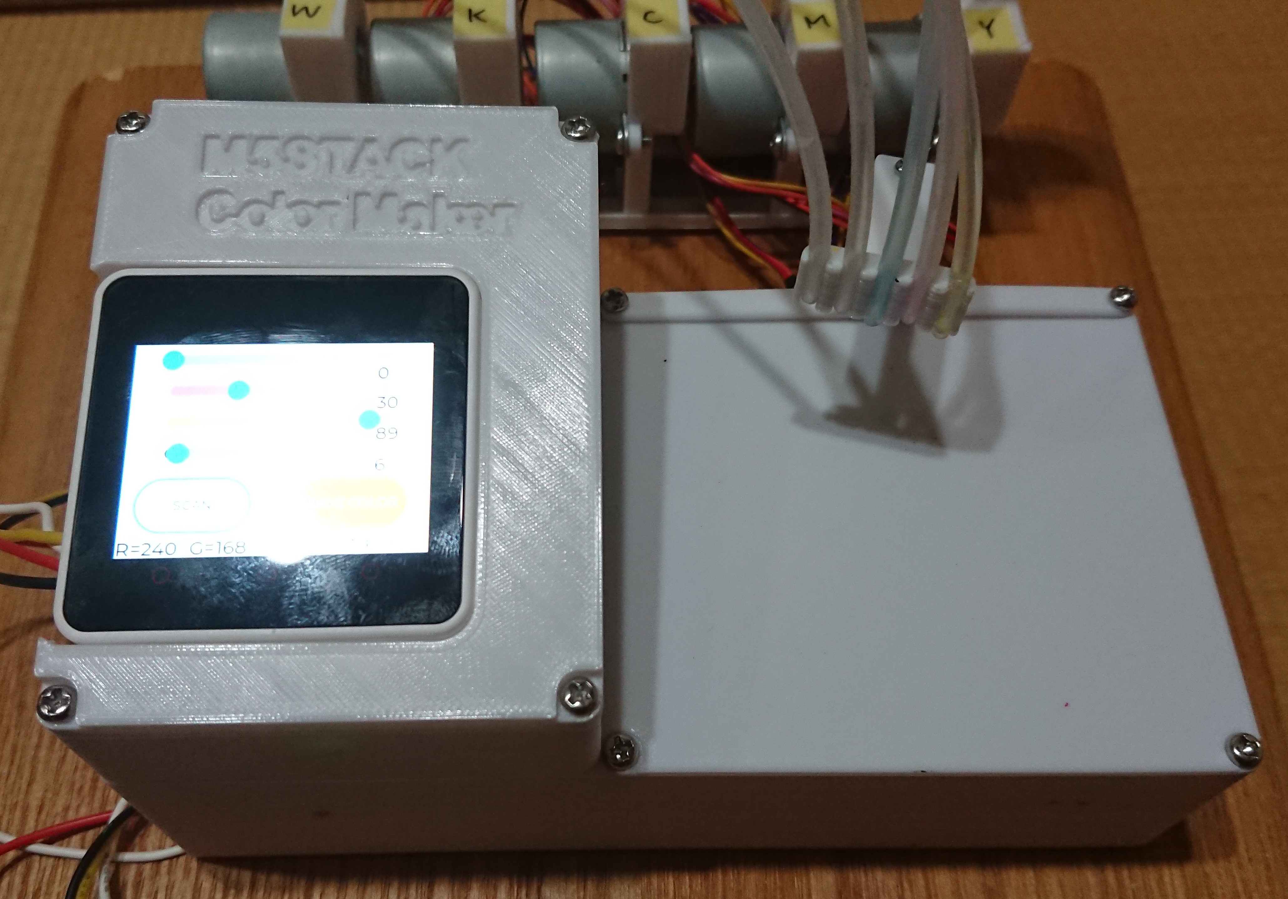
Testing the Color Picker
10/08/2021 at 07:42 • 0 commentsLet's test the color picker using the sensor.
Light colors are recognized as slightly greenish. This is probably because the white LED for reference is not completely white.
Also, the color readings change depending on the distance between the sensor and the object, as well as the surrounding brightness and lighting. In order to stabilize the readings, a cylindrical cover is attached to the sensor case to keep the distance between the sensor and the workpiece constant while shielding it from outside light. -
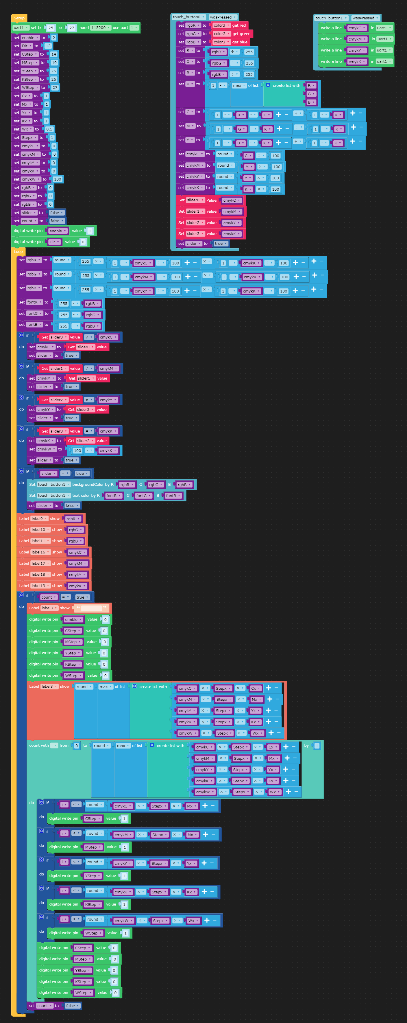
Programming with UIFlow
10/08/2021 at 05:00 • 0 commentsAfter connecting the sensors, write the program in the M5Stack Core2.
The program we have created is as follows. The program file is also attached.
![]()
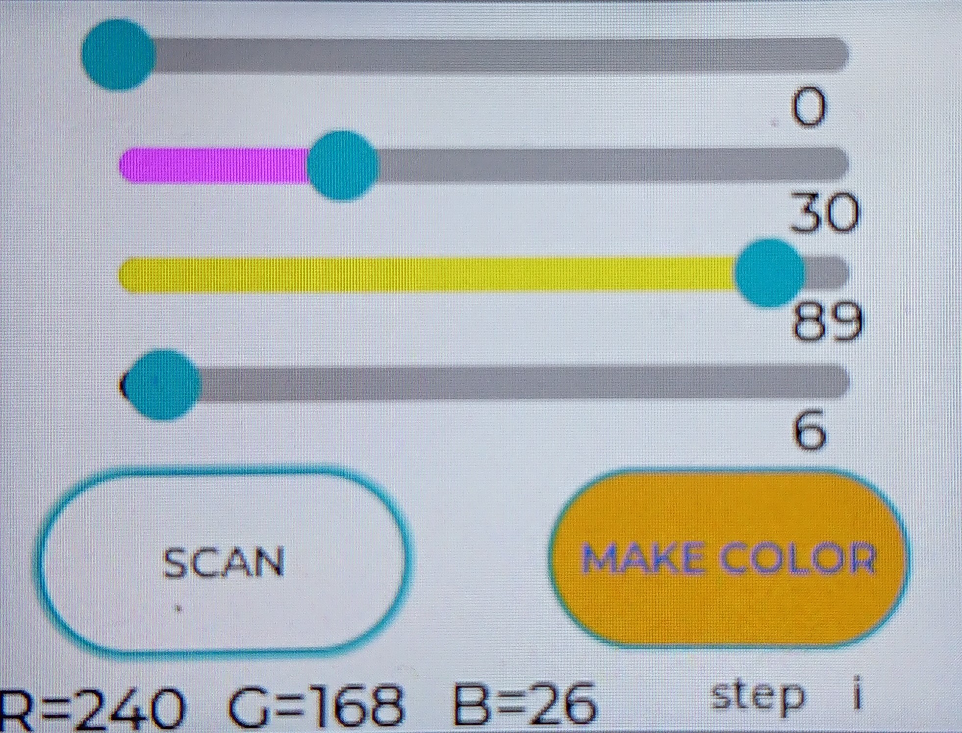
In this program, when you press the "SCAN" button, it reads the color data, converts it to CMYK format, and reflects it on the slider on the UI. By manipulating the slider, you can edit the color as desired.
![]()
The synthesized color is also reflected in the color of the "MAKE COLOR" button.
Clicking the "MAKE COLOR" button will output CMYK data serially.
M5Stack Color Maker
With this device, you can copy the color of an object or create a new color with your imagination.