 Open Green Energy
-
11Mount the PCB
![]()
![]()
![]()
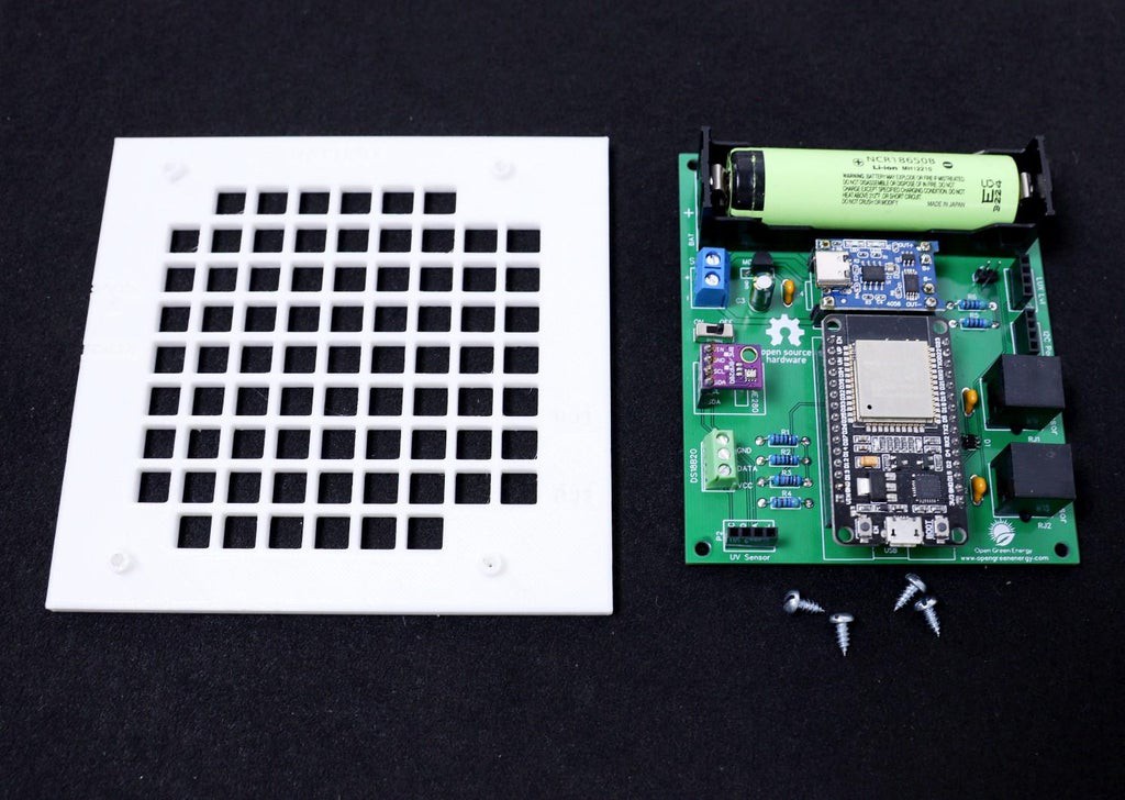
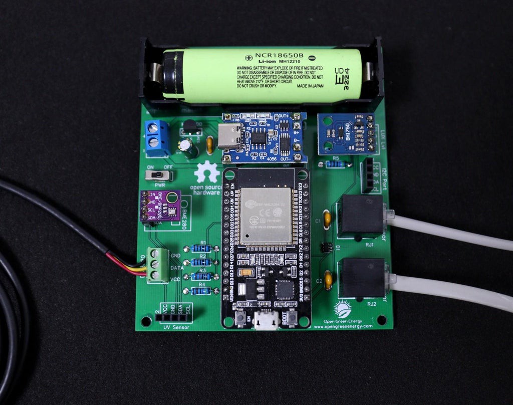
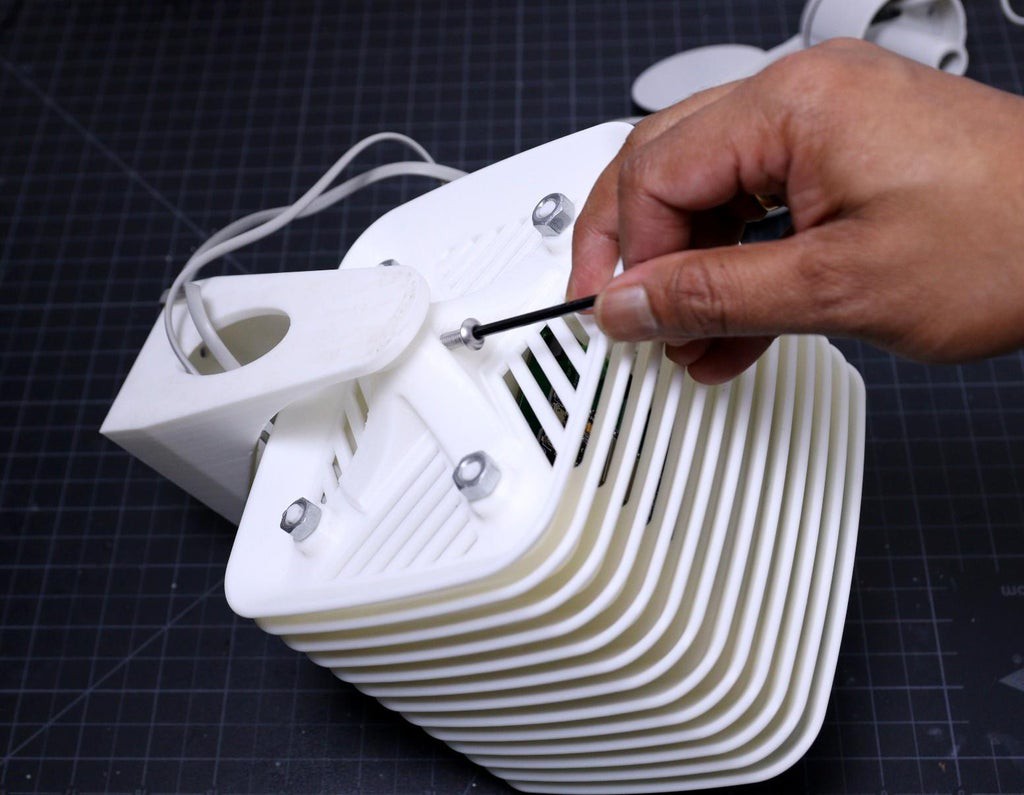
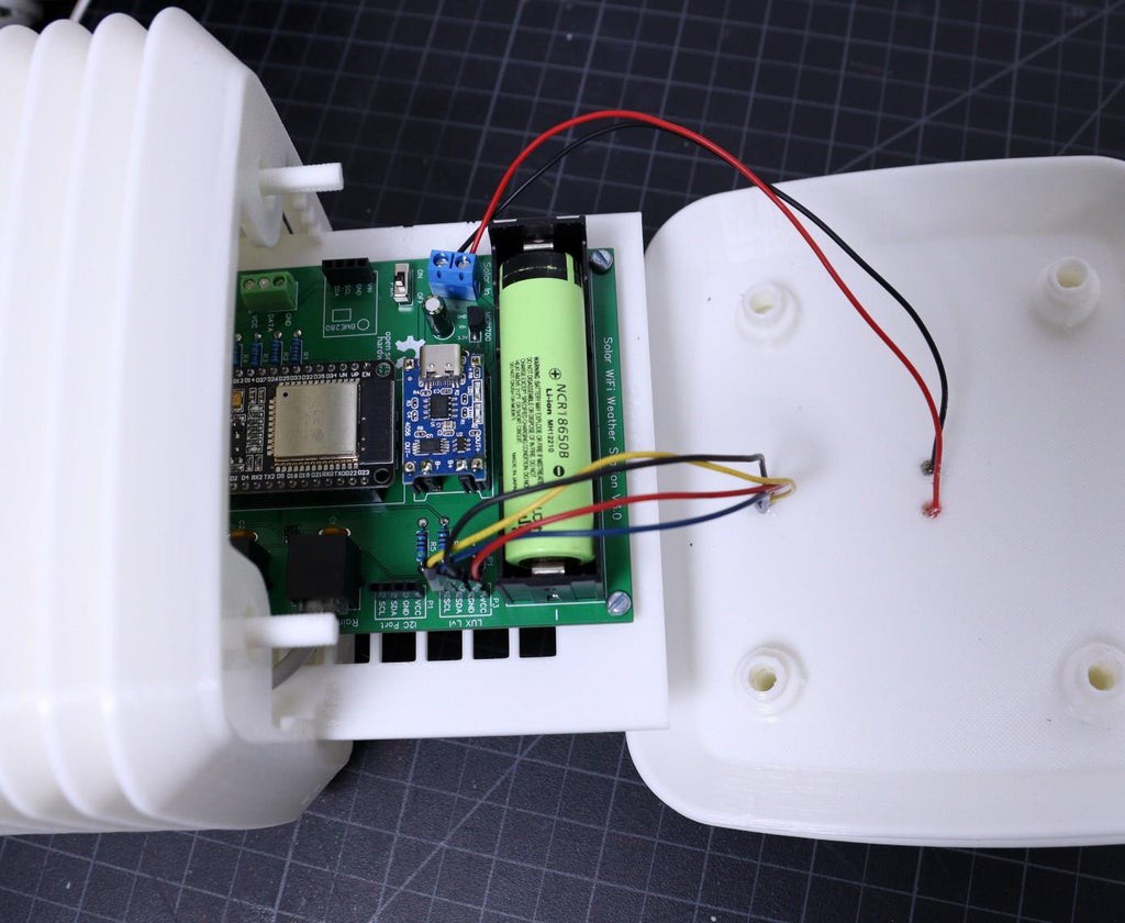
The PCB Mount Frame is designed to mount the V3.0 PCB ( 100 x 86 mm). The PCB mount has text on it to show orientation and the battery goes to the top of the assembly.
Align the PCB in such a way that the battery holder on the PCB and the mounting plate match each other. Once it is matched the other sides will automatically be matched. Now you have to align the PCB holes with the PCB mounting holes ( looks like 4 standoffs ). Then secure the PCB with 4xM3 Nuts.
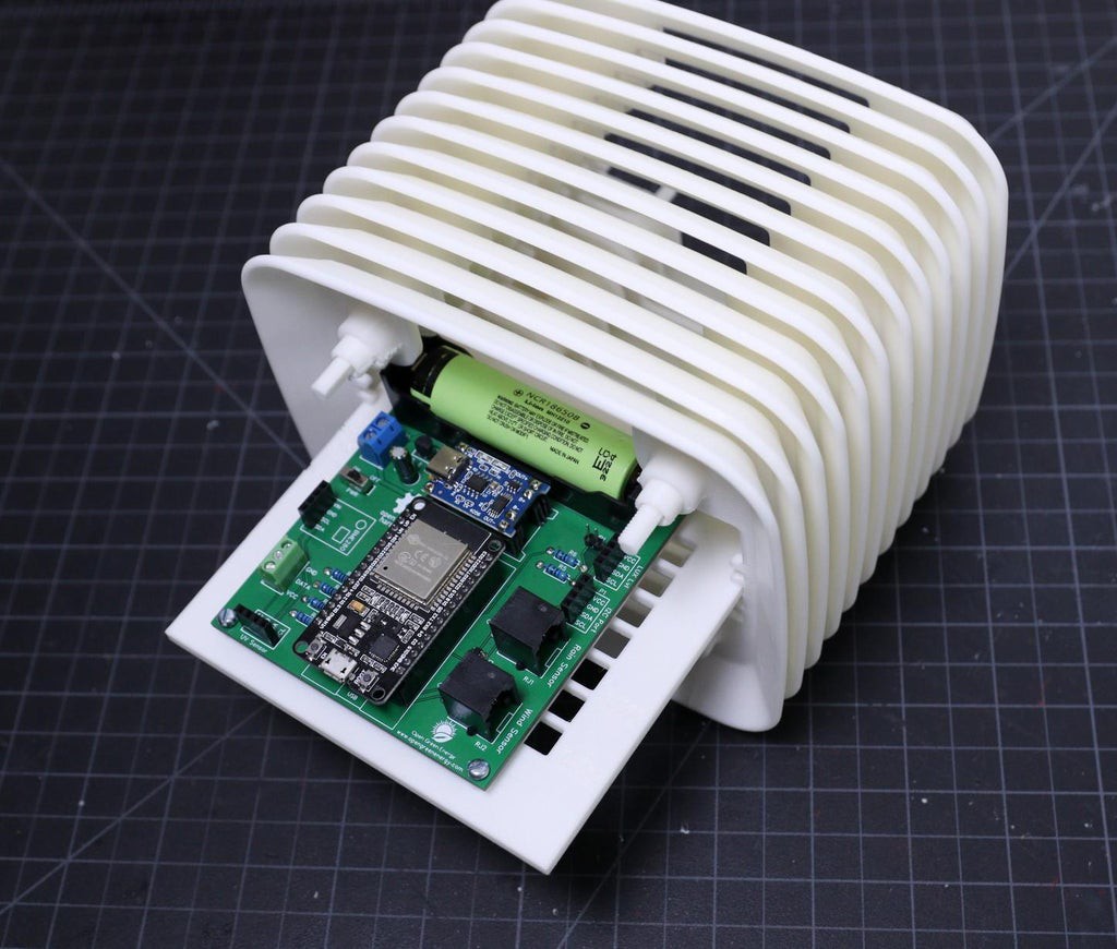
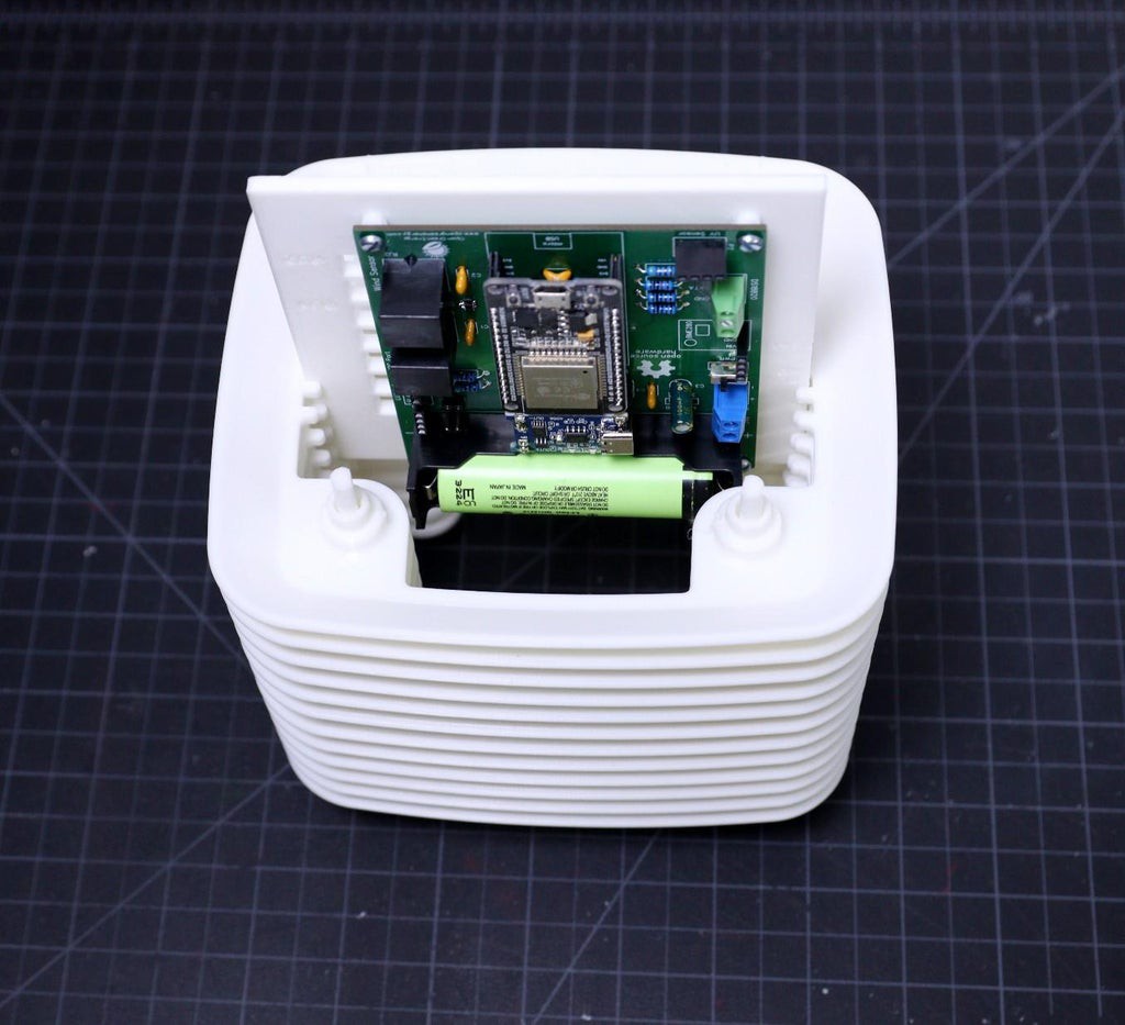
After installing the PCB, slide the PCB mount into the middle ring assembly as shown in the above picture.
-
12Connect the Wind and Rain Sensors
![]()
![]()
![]()
First, insert the two cables from the wind and rain sensor through the round hole in the Bottom Mount. Connect the two cables to RJ11 connectors ( wind and rain sensor) on the PCB. The connector is labeled as " Wind Sensor " and " Rain Sensor ".
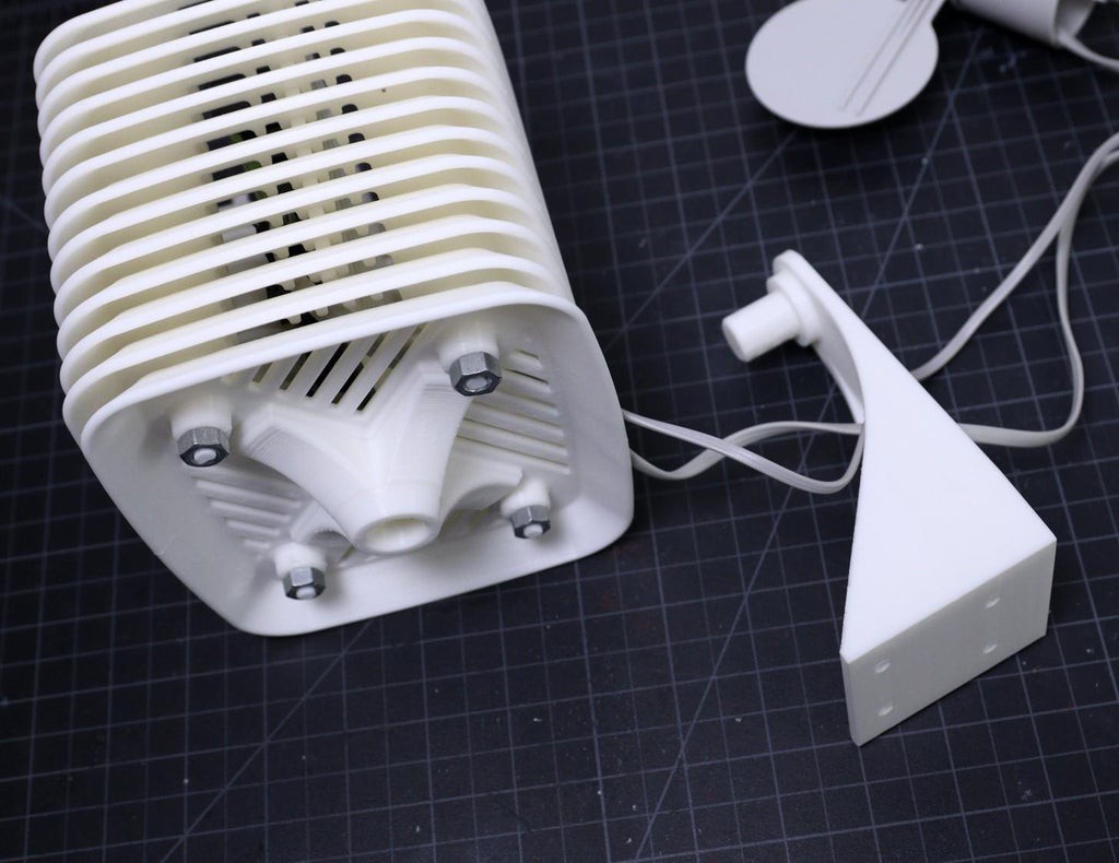
Install the bottom plate and secure it with 4 M3 nuts as shown in the above picture.
Now you can install the bottom mount into the bottom plate and then secure it with a locking nut ( M4).
Note: For a neat and cleaner look, keep the sensor cables toward the bottom mount ( backside ).
-
13Mount the Solar Panel
![]()
![]()
![]()
![]()
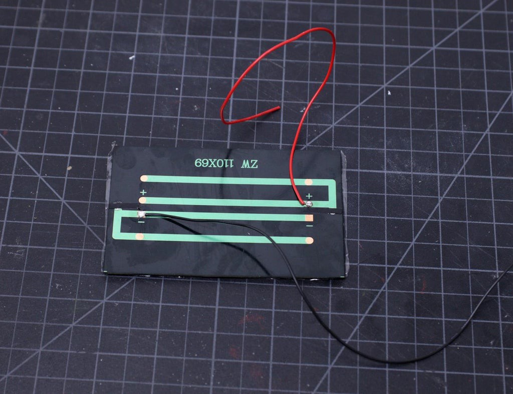
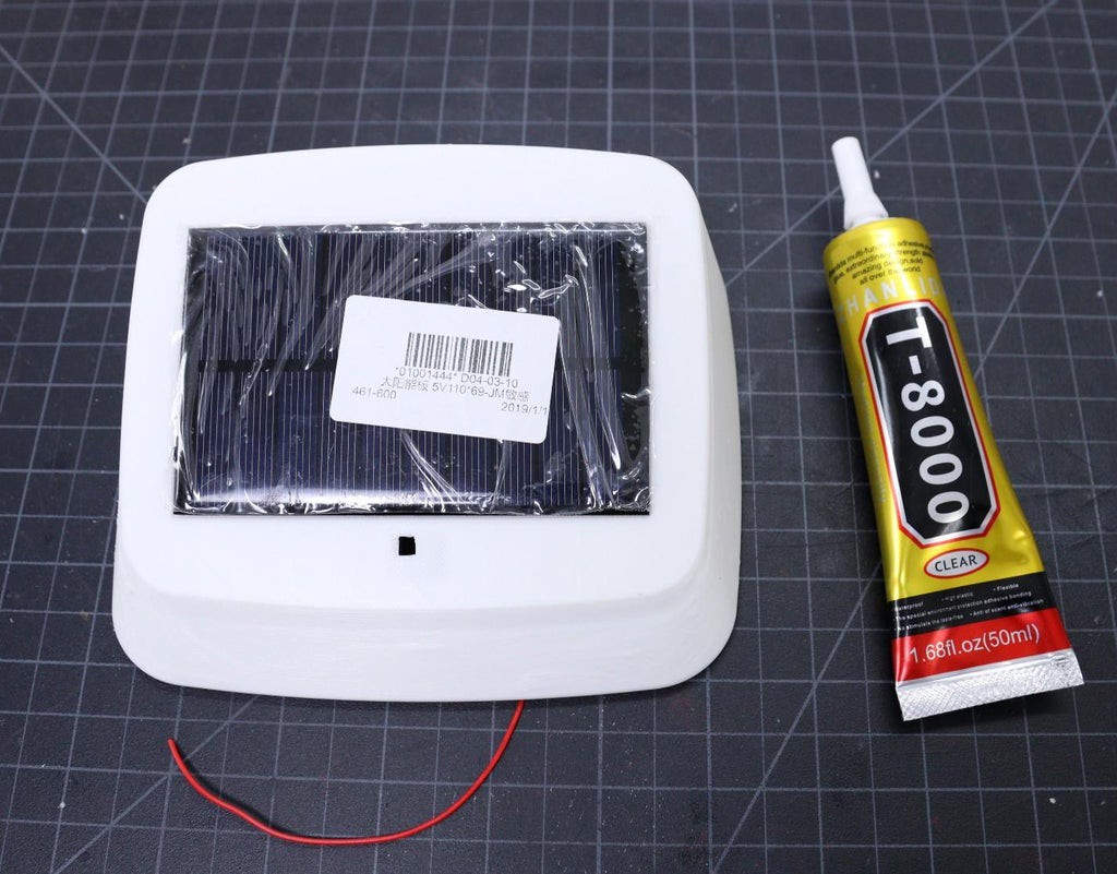
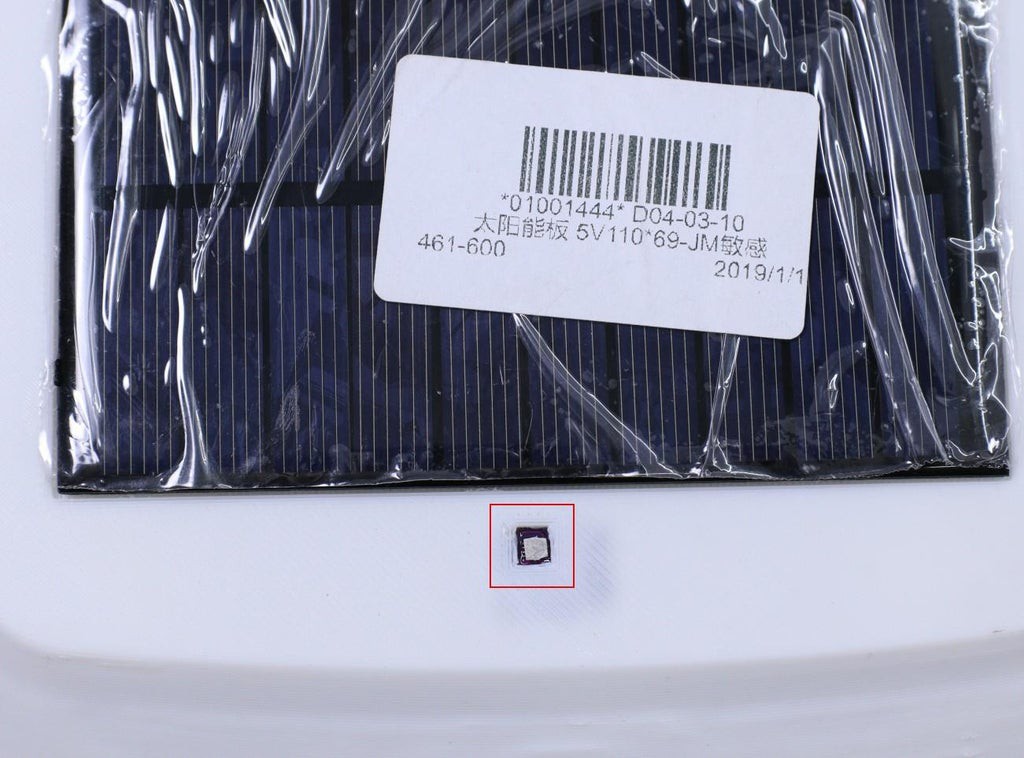
The Solar panel slot in the top cover is designed to hold a 110 x 69 mm solar panel. Here, I have used a 1.25W solar panel.
Apply a small amount of flux to the soldering pads on the solar panel. Then, solder a 22 AWG red wire to the positive terminal and a black wire to the negative terminal of the Solar Panel.
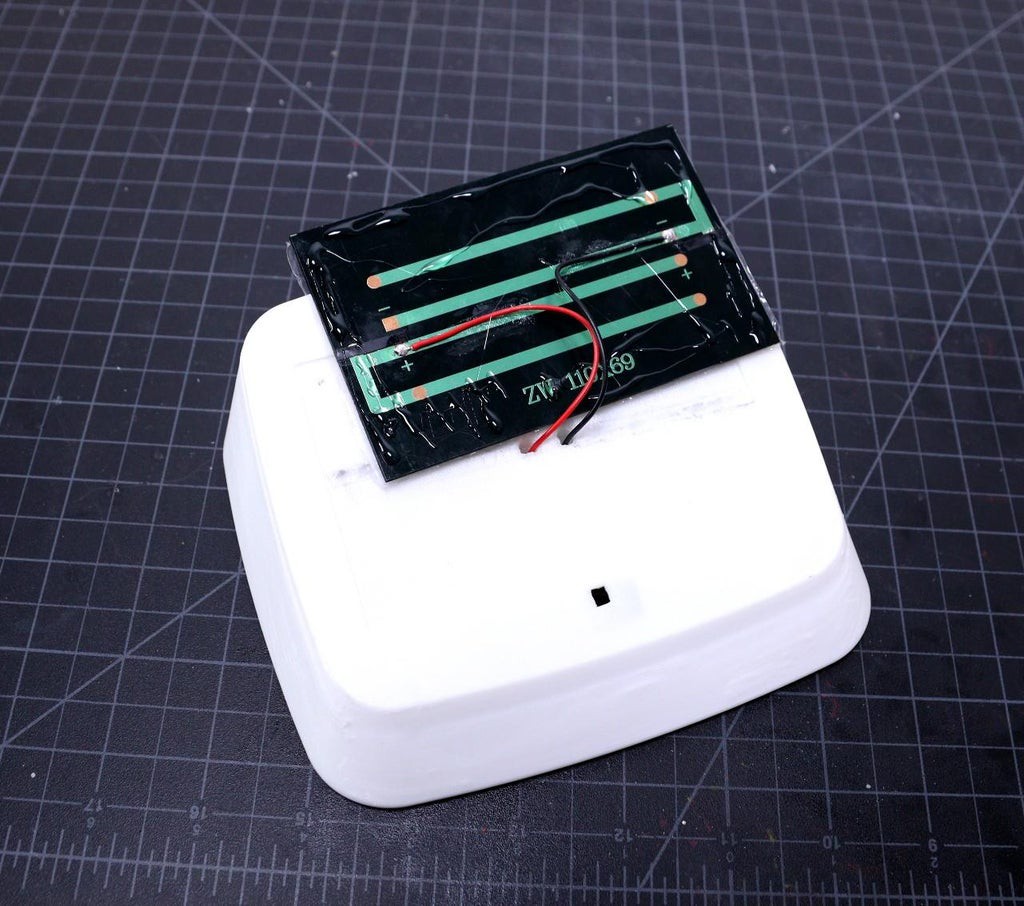
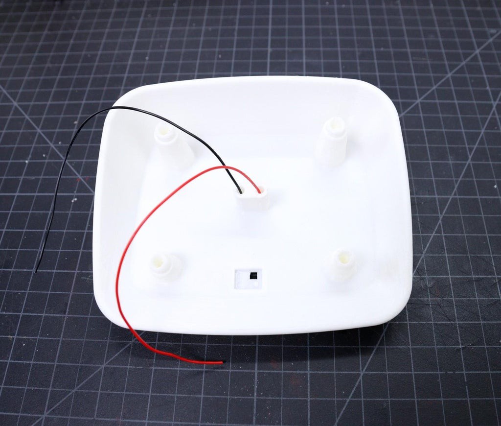
Insert the two wires into the holes in the top cover as shown above. Use silicon glue to fix the Solar Panel and press it for some time for proper bonding. Seal the holes from the inside by using a waterproof sealant or silicone glue. I will recommend not to use hot glue, I have used it in my earlier version, it got melt when exposed to bright sunlight during the hot summer.
Here I have used T-8000 glue for mounting the solar panel as well as sealing the cable holes. It is transparent glue, so it's hardly visible where the glue is used. The main problem with this glue is that it takes a lot of time to dry out.
-
14Mount the UV Sensor
![]()
![]()
![]()
![]()
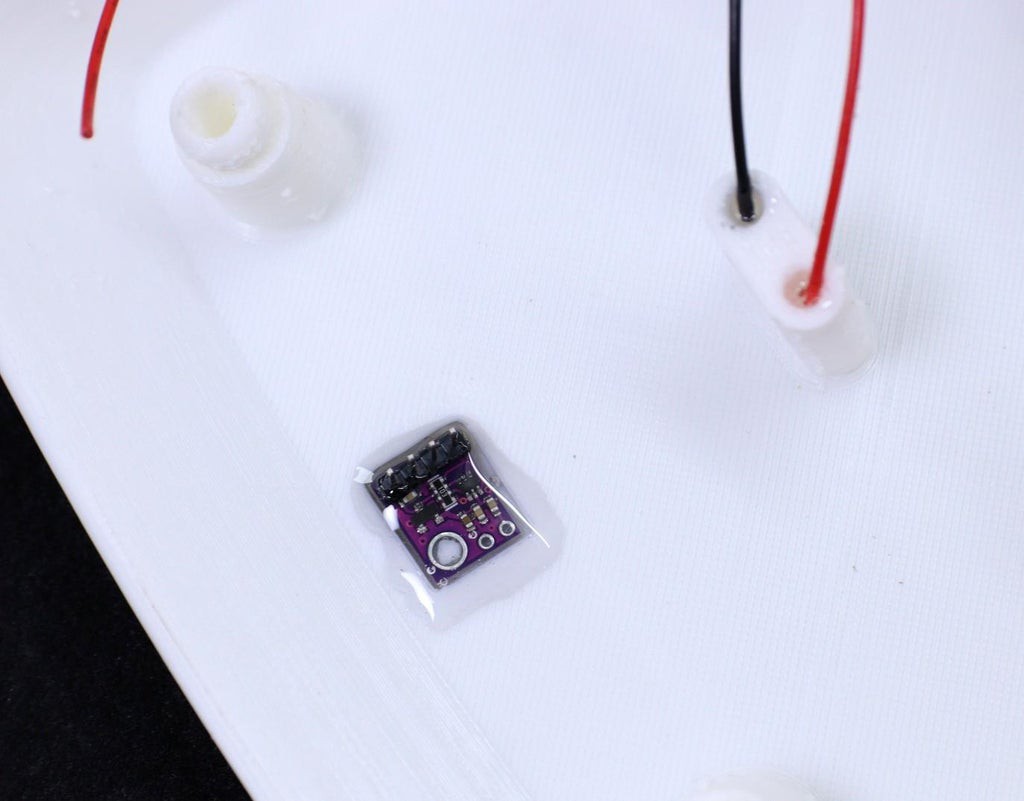
The UV sensor module is comprised of UV sensors along with other electronic components to work it properly. Only the sensor part is responsible for sensing the UV light, so it should be exposed to the light.
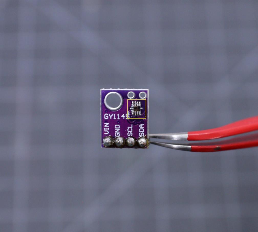
The top cover is designed to hold the UV Sensor module ( GY1145 ) on a peg and a small clearance is given in the slot for the soldering pins on the module.
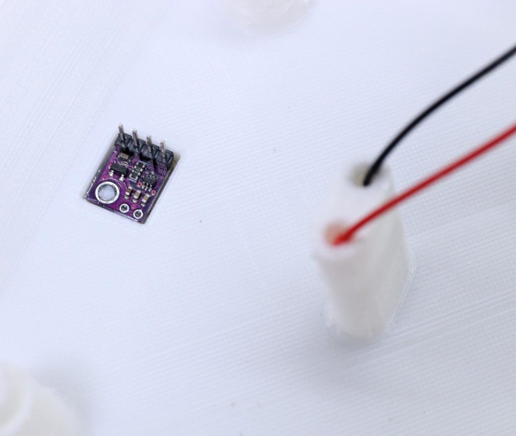
First, cover the UV sensor ( marked in the yellow border - see the image ) by using masking tape, then mount it on the top cover. You may need a small alignment to expose the sensor through the square hole on the enclosure.
Now apply some silicone sealant to stop any water from entering through the opening. After drying the sealant, remove the masking tape by using tweezers. After removal of the tape, you will reveal a clean sensor surface
Note: No window is provided over the UV sensor because it will give a wrong reading.
-
15Connect the Solar Panel and UV Sensor
![]()
![]()
![]()
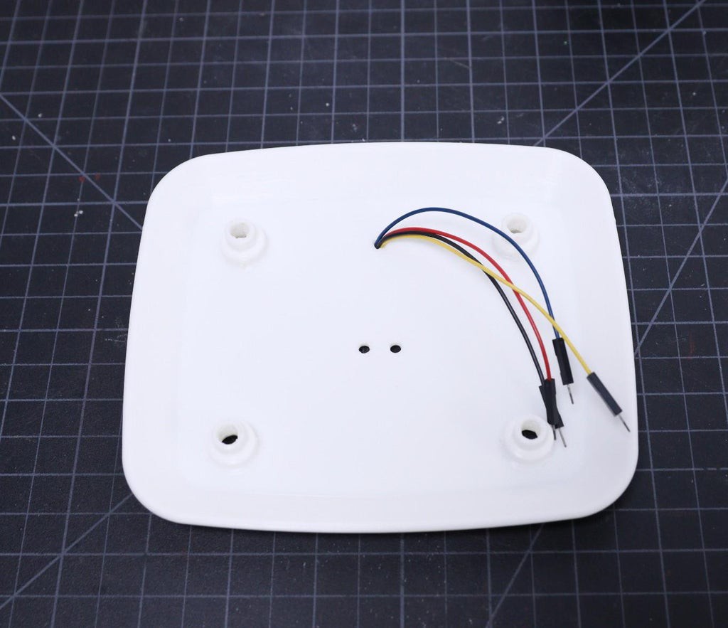
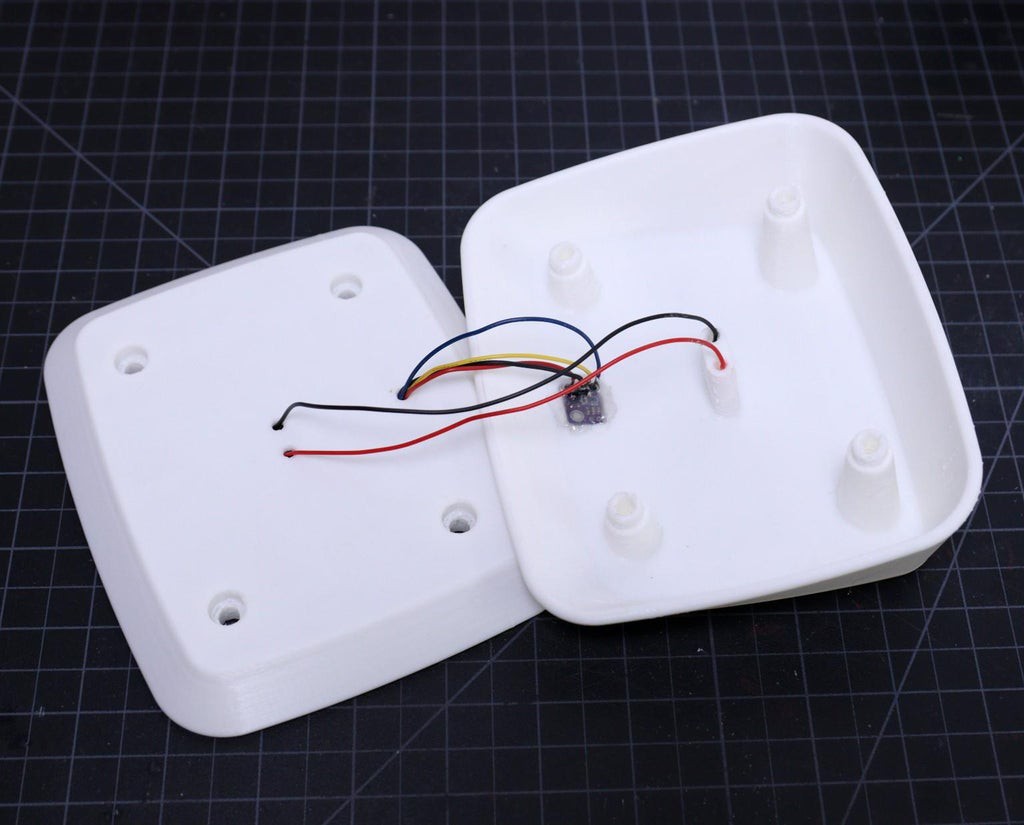
Solder 4 jumper wires to the module pins ( VIN, GND, SDA, and SCL).
There are 3 holes in the top cover, 2 central ones for where the solar panel wires are soldered onto the panel and there is a single hole at the front, this is for the wire from the UV sensor board.
Assemble these wires in place using silicone to seal up the holes.
Now connect the solar panel red wire to the positive and black wire to the negative terminal of the Solar In screw terminal on the PCB.
Then connect the wires coming from the UV sensor to the UV sensor header ( P2 ) on the PCB.
Solar Powered WiFi Weather Station V3.0
ESP32 based Open Source Weather Station
Discussions
Become a Hackaday.io Member
Create an account to leave a comment. Already have an account? Log In.