 Open Green Energy
-
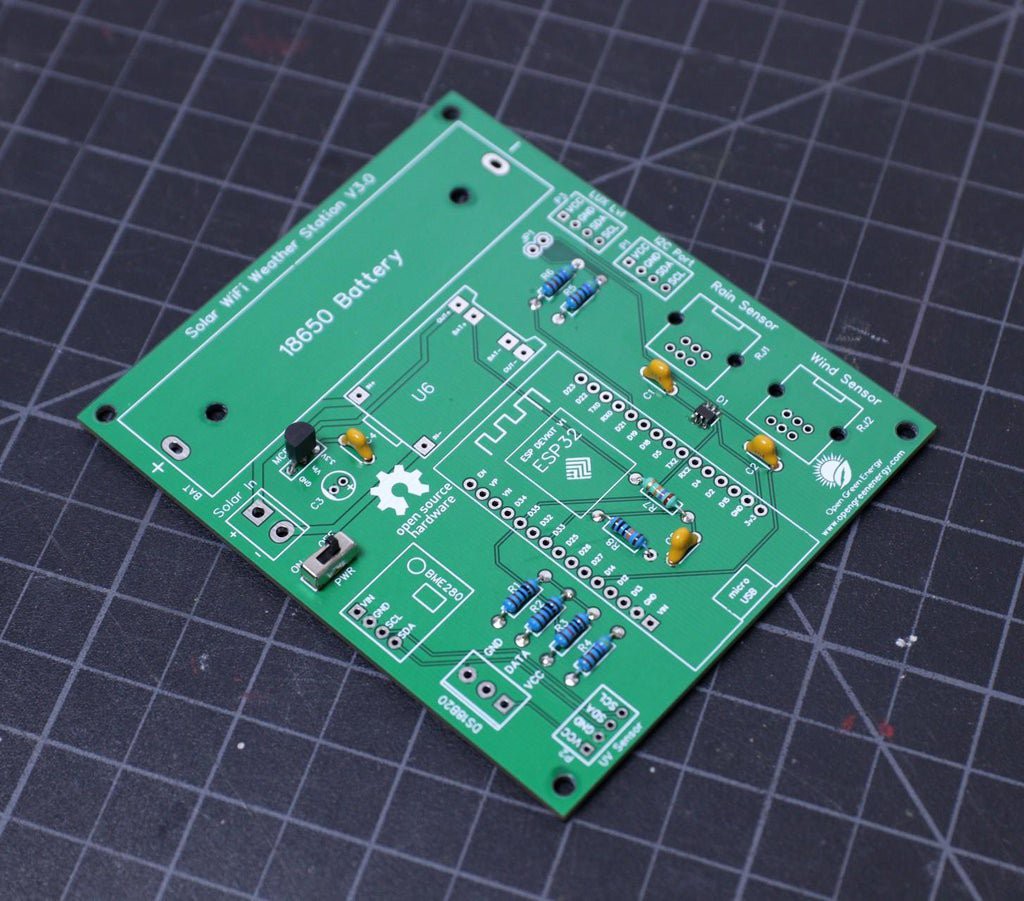
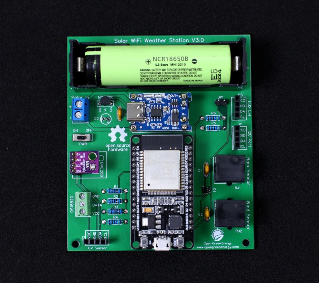
1Assembling the PCB
![]()
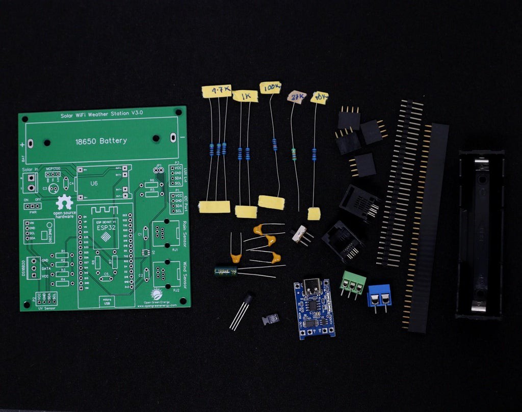
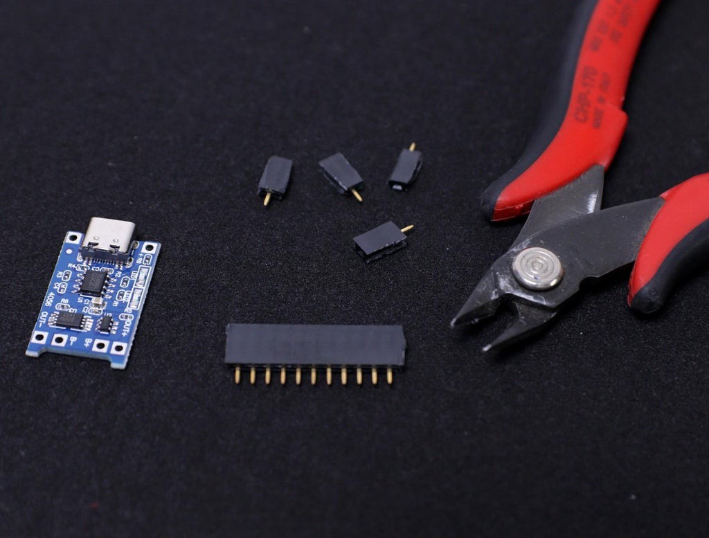
After receiving the board from the PCB fab house, you have to solder the components. For Soldering, you will need a decent Soldering Iron, Solder, Nipper.
First I cut the straight male and female headers pin for ESP32 Board, TP4056, BME280, and jumper JP1. Following are the details about the headers :
1. ESP Board - 2 x 15pins ( Female )
2. BME280 - 1 x 4pins ( Female )
3. UV Sensor - 1 x 4pins ( Female )
4. Lux Level Sensor - 1 x 4pins ( Female )
5. Spare I2C Port - 1 x 4pins ( Female )
4. Jumper JP1- 1 x 2pins ( Male )
It is good practice to solder the components according to their height. Solder the lesser height components first. I have started by soldering the resistors, switch and then moved towards the bigger components like headers pin, screw terminal, and battery holder.
-
2Soldering the TVS Diode
![]()
![]()
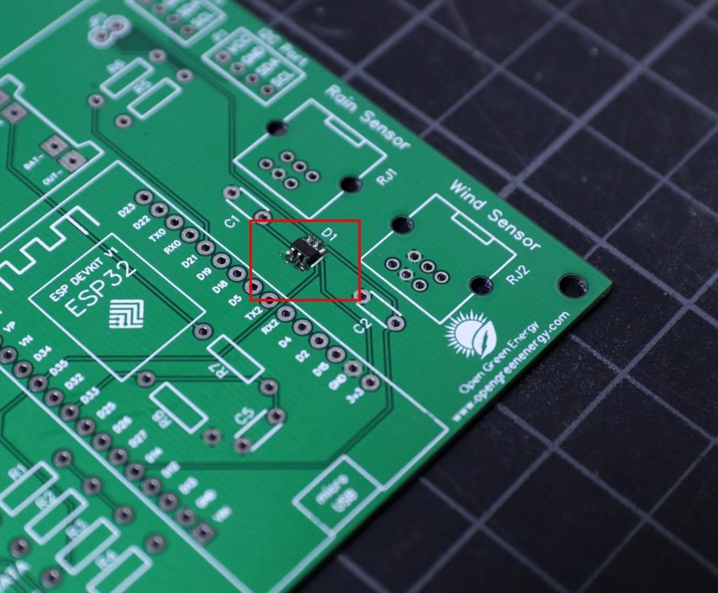
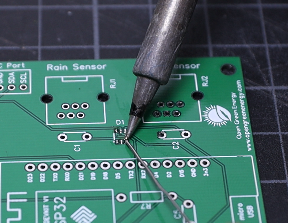
In the entire PCB, the lesser height component is the TVS diode which is the only SMD component used in this project. You can see the datasheet.
First, apply soldering flux on all 6 pads and then apply a small amount of solder to the corner pads. Place and align the diode chip using tweezers. Hold the chip in place while touching the pads with the tip of the soldering iron so that the solder melts the pin and the pad together.
Be sure the dot symbol on the PCB and the TVS diode is matching together. The dot symbol represents pin number -1.
Now apply solder to all the pads, and you are done. If you mess up during the soldering, you can remove the extra solder by using a desoldering wick.
You can read this tutorial if you are new to soldering SMD components by using a soldering iron. By the way, I am also learning.
Note: Without the use of this TVS diode not affect the functionality of the weather station, it provides additional protection to the circuit.
-
3Soldering the Resistors and Ceramic Capacitor
![]()
![]()
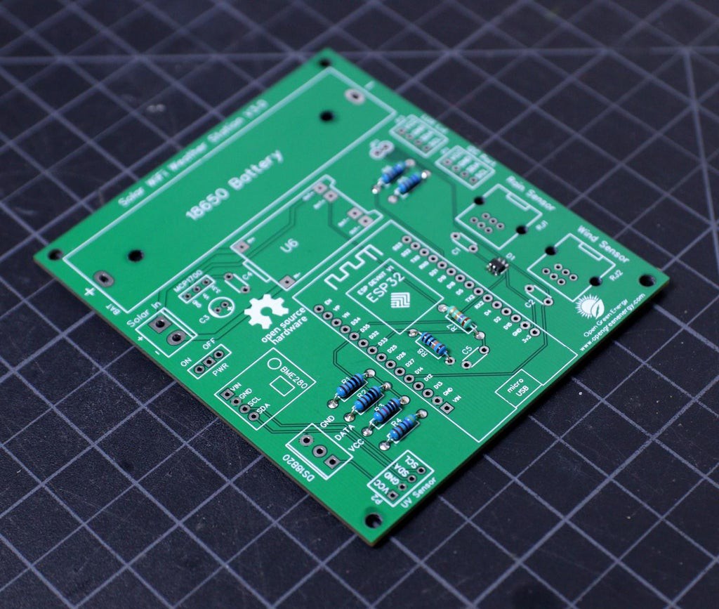
By considering the component height, after the TVS diode, the next component is the resistor and then ceramic capacitors. Bend the resistor legs and insert them into the PCB holes. Solder the legs and trim the extra legs by using a nipper.
During soldering always refer to the schematic diagram to avoid any mistakes. The schematic diagram is attached below. You should take a printout and keep it side when soldering.
Similarly, solder the ceramic capacitors. Note that ceramic capacitors do not have any polarity, so you can solder in any way, it will work.
-
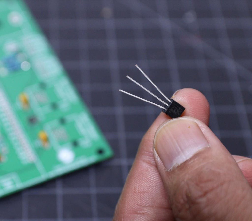
4Soldering the LDO MCP1700
![]()
![]()
The LDO MCP1700 used in this project comes in the TO92 package in which the pin-to-pin distance is only 1.26mm. So if you are a beginner, you may short the pads during the soldering, to avoid this I have not used the TO92 package footprint on the PCB. I intentionally provided some gaps in between the soldering pads.
Stretch the 3 legs of MCP1700 as shown in the above picture, then insert it into the PCB holes where it is labeled as MCP1700.
The pinout diagram is shown above, each pin name is also labeled on PCB so that you will not confuse during the soldering.
-
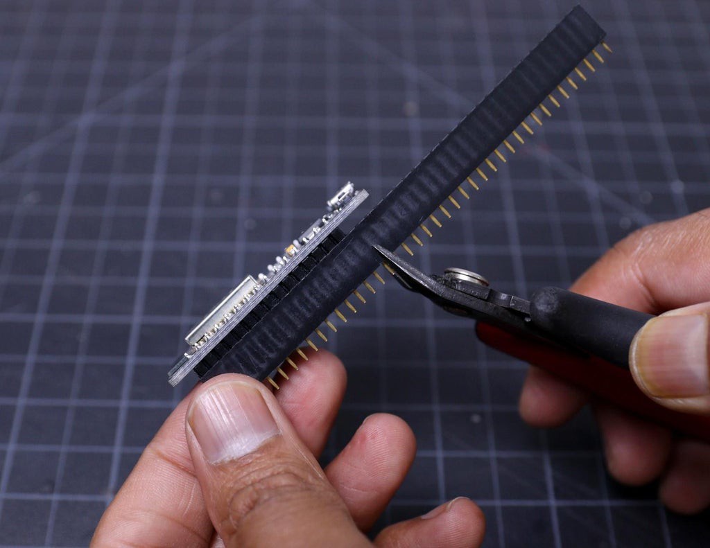
5Trim the Headers
![]()
![]()
![]()
![]()
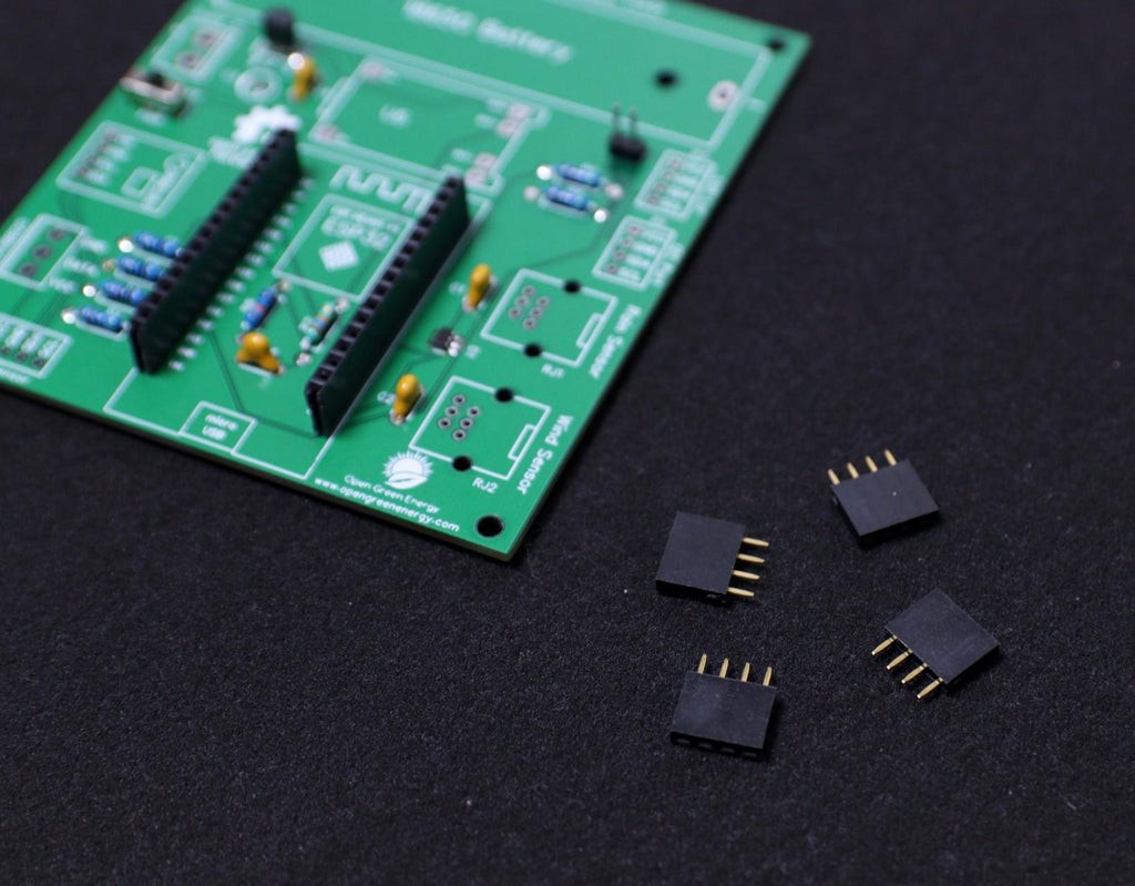
The best way to trim the female header pieces is to count out 15 pins, pull the 16th pin, then use a nipper to cut the gap between the 15th and 17th pin.
You must be careful when cutting the header to center your snip. An off-center cut may result in the mechanical portion of the header escaping or losing some of its retention force.
Optionally, you may take a file, piece of sandpaper to sand down the end of the header so that it will look very smooth.
I followed the above principle to prepare all the female headers.
-
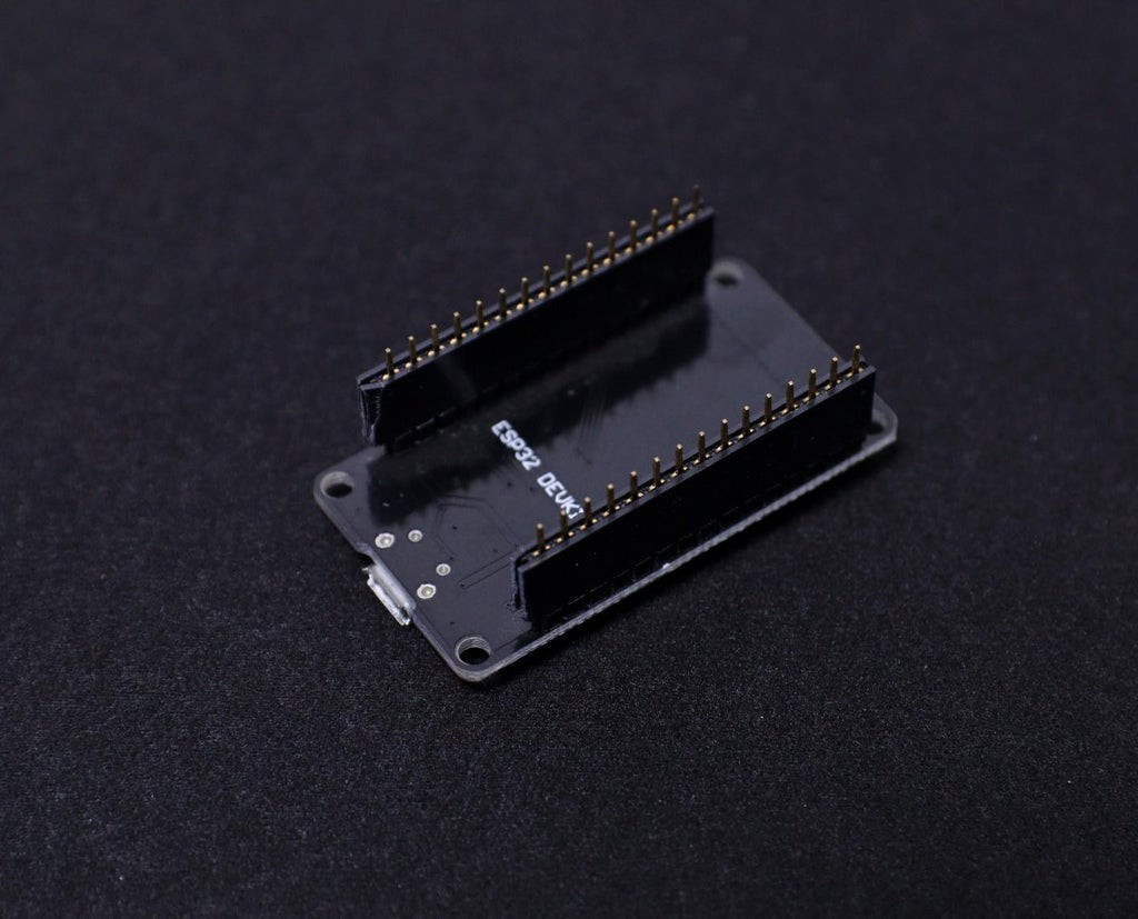
6Soldering the Headers
![]()
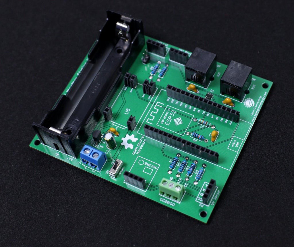
Plug all four headers into the PCB. The PCB is labeled to identify which header goes to which place. The male pins of the header should enter the top side of the PCB and extend out the bottom. I always solder two-end pins first, then solder the remaining pins.
It's important that each of the headers is at a nice, 90° angle to the PCB. This will ensure that the ESP32 board/ sensor modules will slide straight onto the headers, and you won't have to bend any pins in doing so.
To mount the TP4056, here I have used 6 x 1 female pin, you may use male pins too.
Trim the extra legs by using a nipper.
-
7Soldering the Bigger Components
![]()
![]()
The bigger components on the PCB are the terminal connectors ( two screw terminals and two RJ11 connectors) and the 18650 battery holder. First solder the two screw terminals then solder the RJ11 connector. The RJ11 connector has some locking arrangement, you have to insert it into the two side holes on the PCB.
-
8Adding the Modules and Battery
![]()
![]()
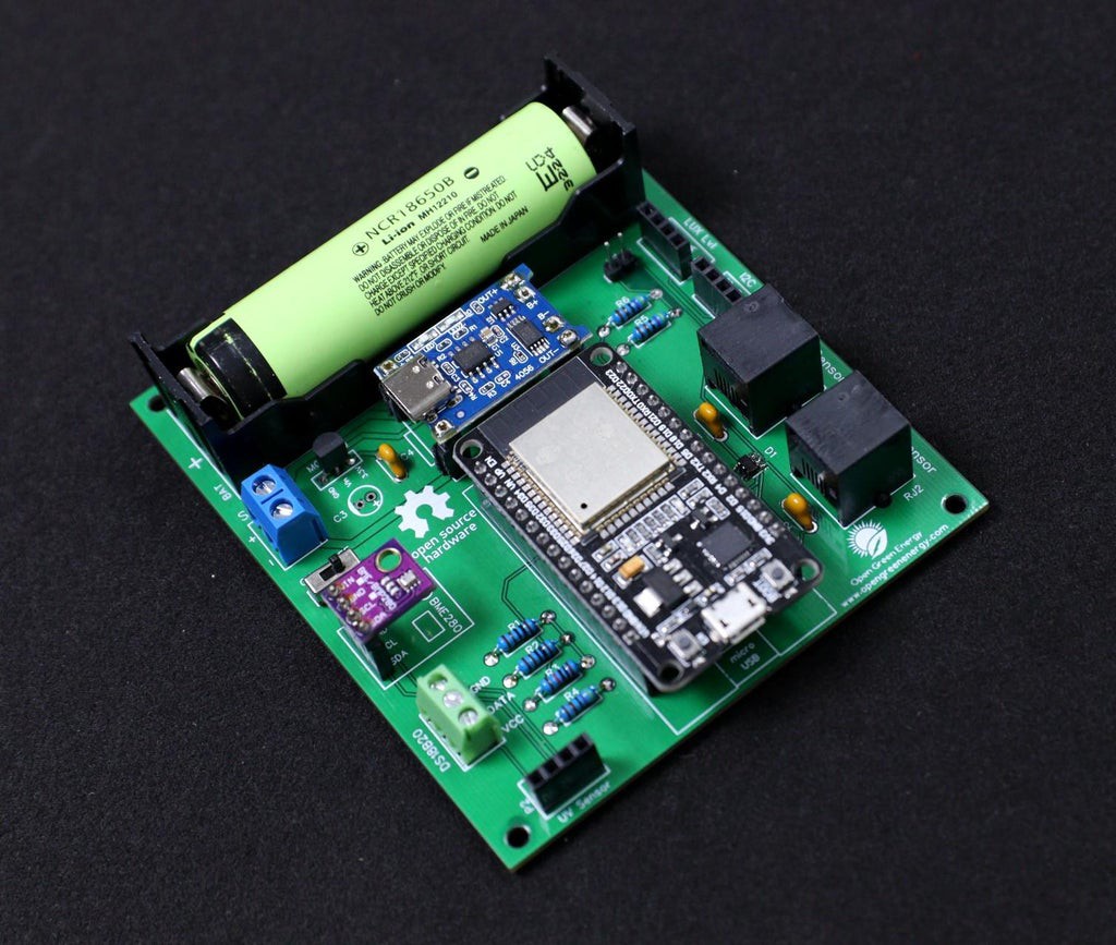
After assembling the header pins, switch, Connectors, and screw terminal, it is time to insert the boards into their respective headers. The headers are clearly labeled on the PCB, so there is no chance of confusion.
First I place the TP4056 board and solder all the pads.
Then I added the ESP32 Board and BME280 Sensor.
Finally, I inserted the 18650 battery into the battery holder.
-
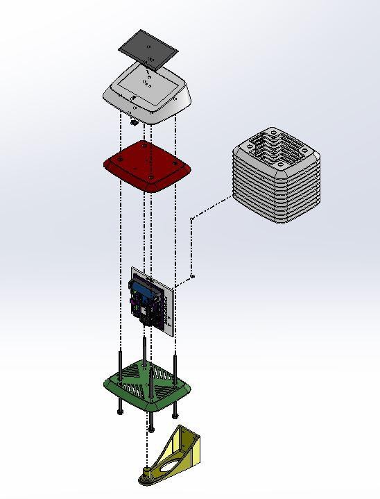
9Assemble the 3D Printed Parts
![]()
![]()
![]()
![]()
![]()
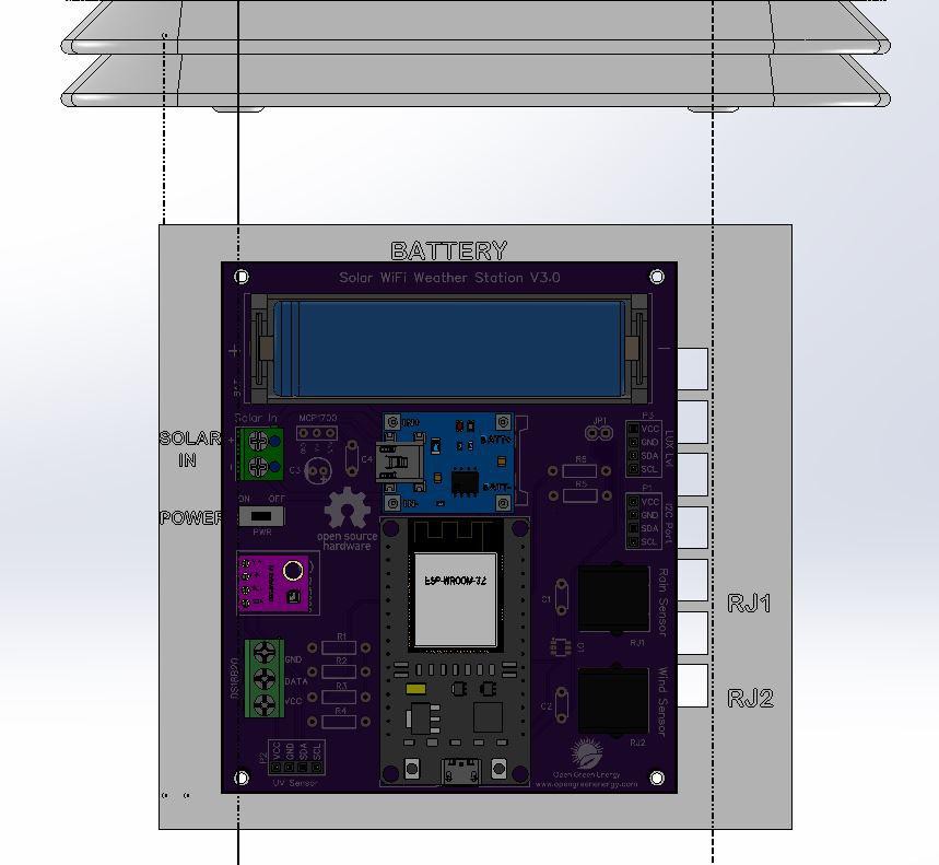
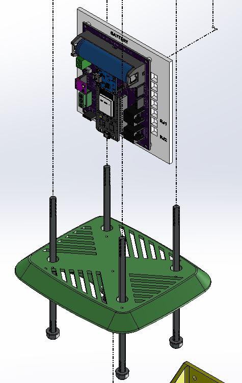
The assembly process is clearly indicated in the explosion diagram shown above. It is broadly as below:
1. Stacking 12 numbers of middle rings one above the others
2. Mounting the PCB
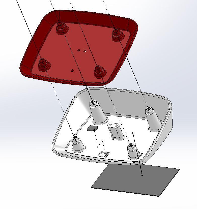
3. Mounting Solar Panel and UV Sensor on Top Cover
4. Joining the Bottom plate, Middle ring, and Top Cover
-
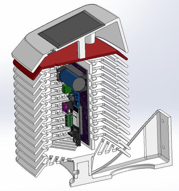
10Assemble the Middle Rings
![]()
![]()
![]()
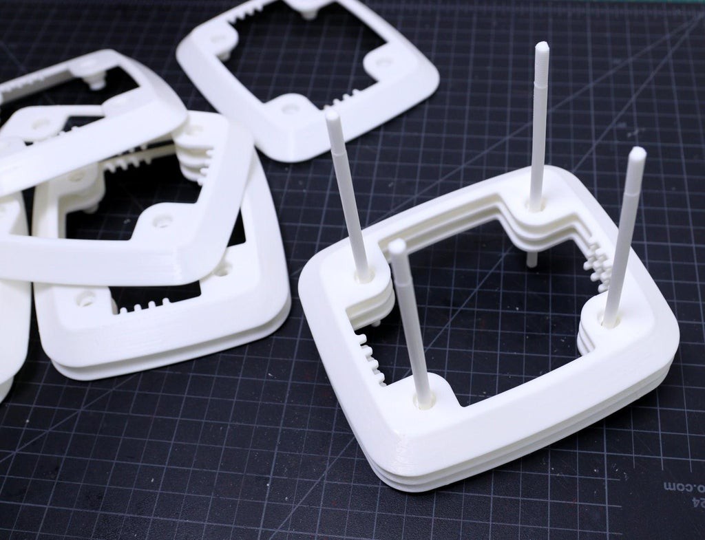
The assembling process is very simple, just stack one above the others. After stacking all the middle rings, insert the 4 x M6 rods at the corners. The M6 rods can be a metal one or 3D printed one, here I have used the 3D printed rods.
If you are using 3D printed rods, then I will suggest inserting the M3 rods at the early stage, i.e. after stacking 2 or 3 rings is perfect. Then insert the remaining middle rings one by one. I have broken 2 rods during the assembling because I did one mistake that stacked all the rings first and then tried to push the rods at the corner holes.
Solar Powered WiFi Weather Station V3.0
ESP32 based Open Source Weather Station


Discussions
Become a Hackaday.io Member
Create an account to leave a comment. Already have an account? Log In.