Open Green Energy
-
Weather Station Installation
10/08/2021 at 10:02 • 0 comments![]()
![]()
![]()
![]()
![]()
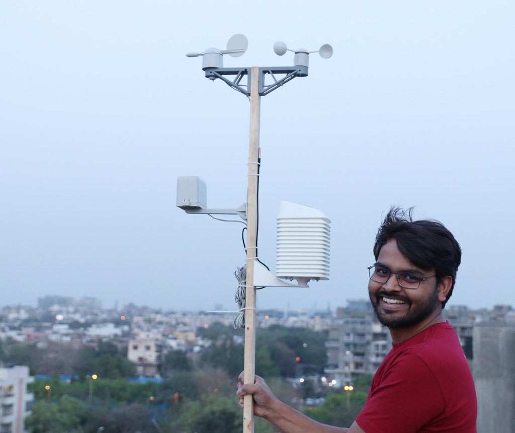
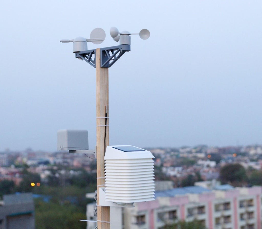
Once you have confirmed that your weather station PCB along with all the sensors, working perfectly, you need to design and make a mount for it. I have used a wooden pole ( 4cm x 8cm x 300 cm ) to mount the sensors and the 3D-printed Stevenson Screen.
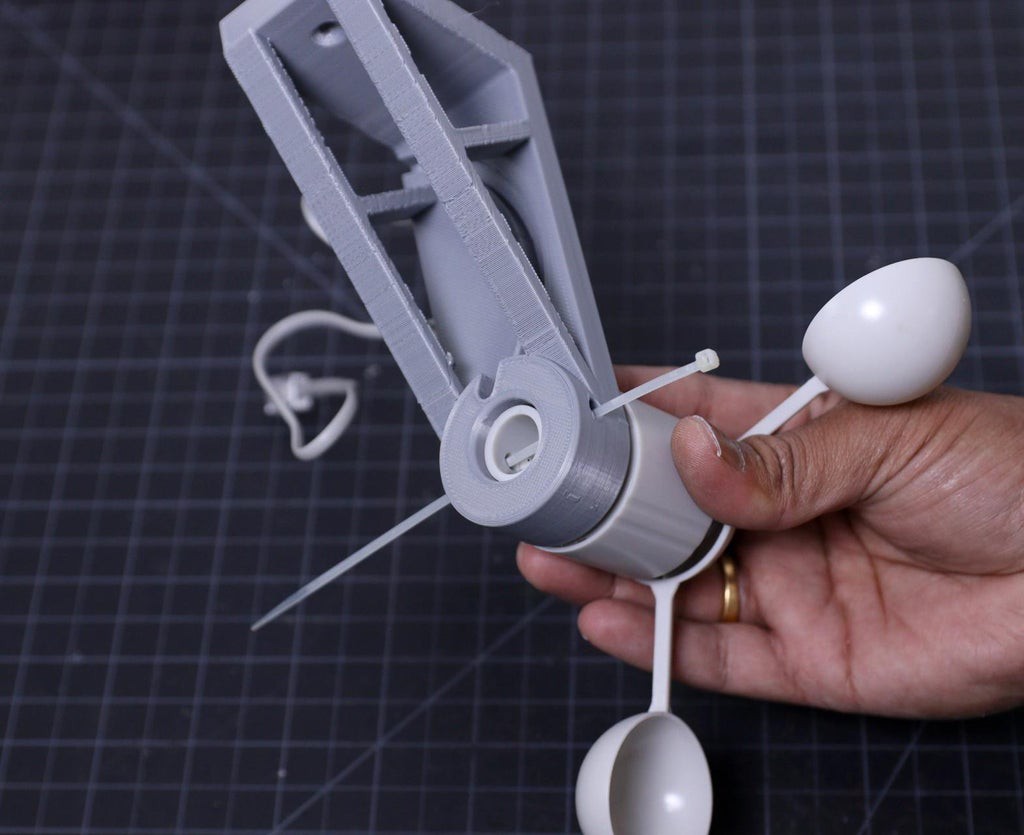
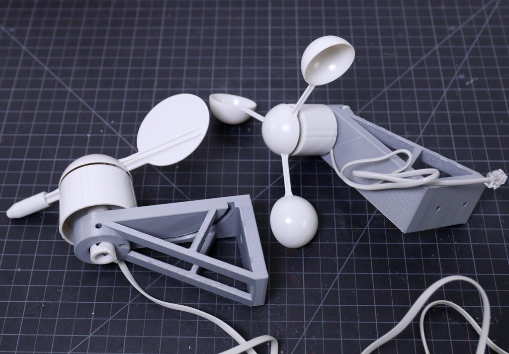
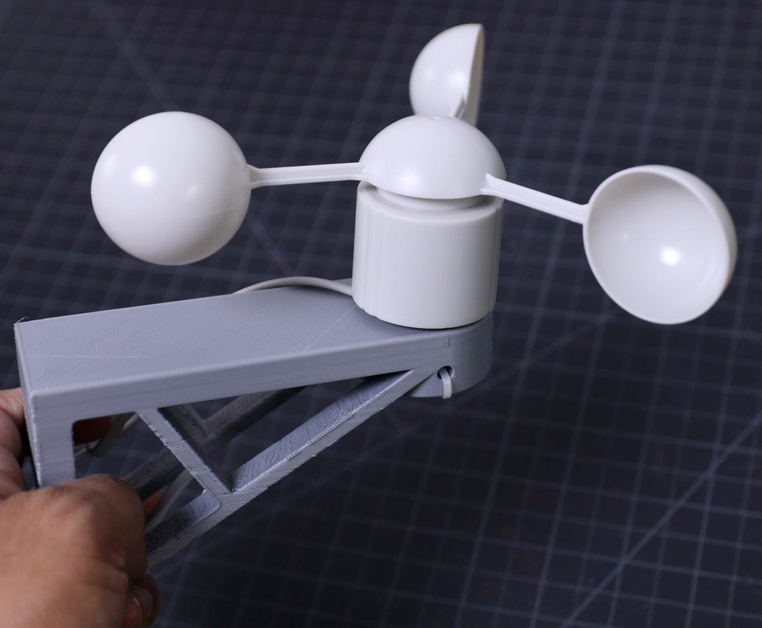
If you purchase the entire Weather Meters Kit, then you don't have to worry about mounting the wind and rain sensor. But if you purchase the independent sensor, you may need some mounting arrangements. I found a nice wind sensor holder from Thingiverse.
First I mount the wind sensors ( Wind Vane and Anemometer ) by using the 3D printed wall mounts. I have installed the wind vane and anemometers by using cable ties. After that, mounted them on the wooden pole by using two screws. You can see the above picture for a better understanding.
Similarly, I have mounted the rain sensor on the wooden pole. But the holder used for it is a ready-made one. In the future, I will make a 3D printed holder for it so you don't have to buy it.
At last, mount the external temperature sensor ( DS18B20 ) on the pole by using cable ties. After installing all the sensors, you have to route all the cables from the sensors to the Stevenson Screen.
Note: Always use good quality cable ties which is specially made for outdoor use ( UV-resistant ).
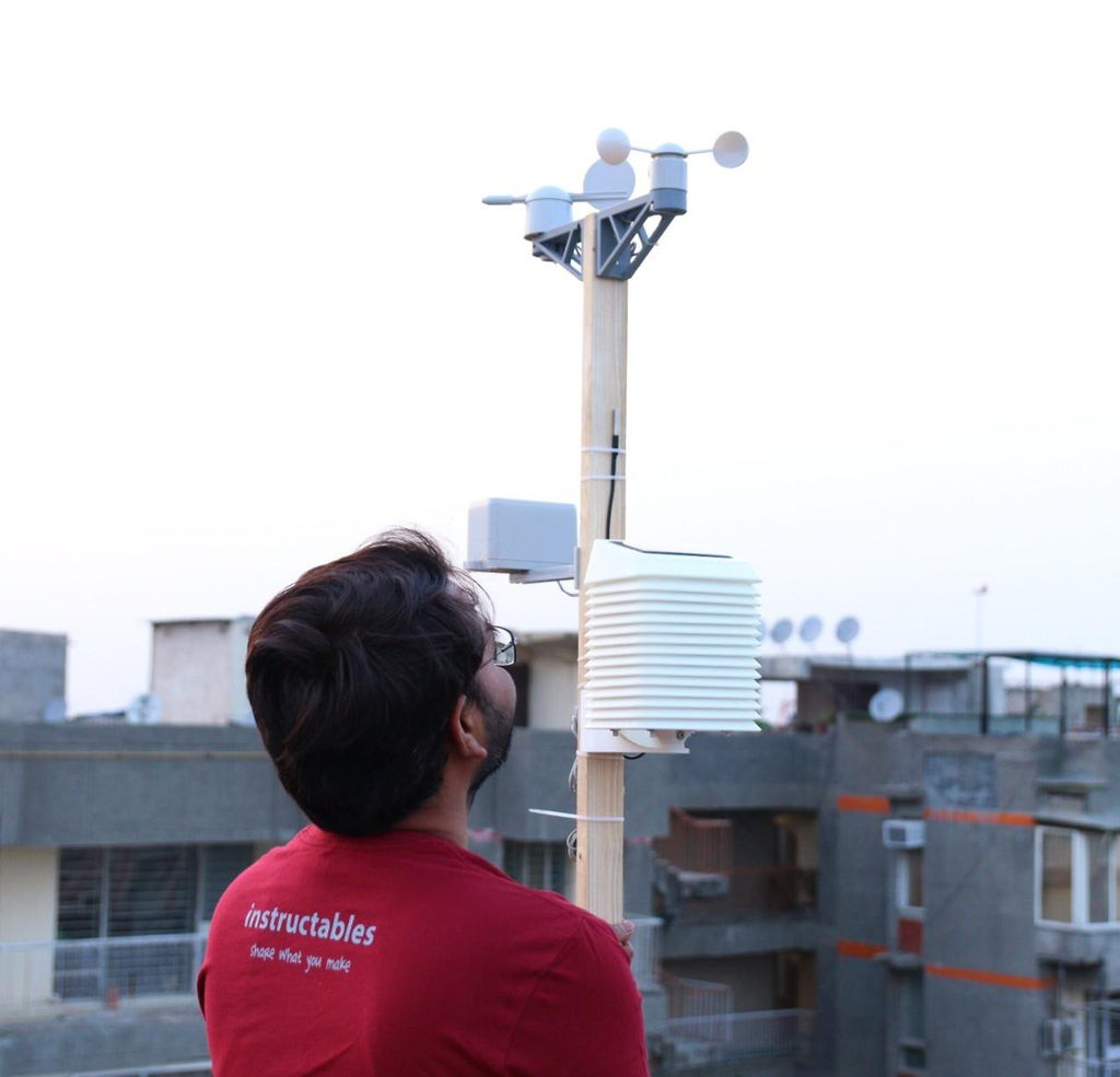
Now it is time to install the Stevenson Screen which we have made earlier. Install the Bottom Mount on the wooden pole by using 4 screws.
Suitable Location for Installation:
The location of your weather station is the most important part of the installation. If your weather station is located under a tree or an overhang, the rainfall data measured by the station will not be correct. If you place your weather station in an alley, you could very well get a wind tunnel effect on the anemometer, resulting in erroneous wind data. If you want to measure sunlight you cannot have the sensor in a shadow. So make sure that there is sufficient clearance around and above the weather station.
You can read this nice article on Weather Station Installation.
-
Conclusion and Future Goal
10/07/2021 at 15:03 • 0 comments![]()
It took me a lot of time to make the circuit, making the PCB prototype, rectifying the errors in the PCB prototype, testing the PCB, making the enclosure, and then assembling and installing them. So I had not enough time left to concentrate on the software part. I am entering this project in Microcontroller Contest, the deadline is 29.03.2021. So I have no option to wait and complete the full software. The software attached here is a basic building block of the project, I will update it regularly with new features.
My future goals are :
1. Software for Implementing ESPHome and Home Assistant2. Software for implementing MQTT
3. Optimizing the Power Consumption
4. Implementing LORA communication ( Probably in V4.0 )
Comments and feedback are always welcome.
-
Interfacing With Blynk App
10/07/2021 at 15:02 • 0 comments![]()
![]()
Blynk is the most popular Internet of Things platform for connecting any hardware to the cloud, designing apps to control them, and managing your deployed products at scale. With Blynk Library you can connect over 400 hardware models including ESP8266, ESP32, NodeMCU & Arduino to the Blynk Cloud.
Step-1: Download the Blynk app
1. For Android
2. For iPhone
Step-2: Get the Auth Token
In order to connect the Blynk App and your hardware, you need an Auth Token.
1. Create a new account in the Blynk App.
2. Press the QR icon on the top menu bar. Create a clone of this Project by scanning the QR code shown above. Once it detected successfully, the whole project will be on your phone immediately.
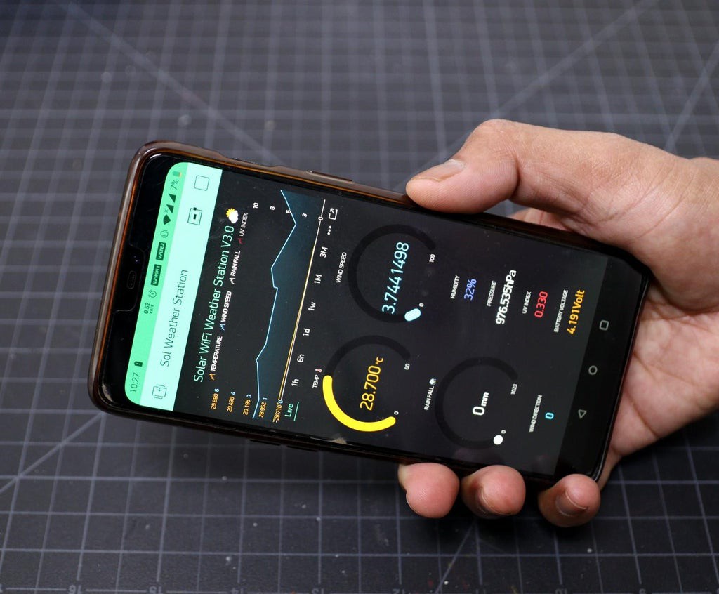
I've made the Sol Weather Station app. You are welcome to try it out!
To start using it:
1. Download Blynk App: http://j.mp/blynk_Androidor http://j.mp/blynk_Android
2. Touch the QR-code icon and point the camera to the code below 3. Enjoy my app!
3. After the project was created, we will send you Auth Token over email.
4. Check your email inbox and find the Auth Token.
Step-3: Preparing Arduino IDE for Wemos Board
To upload the Arduino code to Wemos board, you have to follow this InstructablesStep-4: Arduino Sketch
After installing the above libraries, paste the Arduino code given below. Enter the auth code from step-1,ssid, and password of your router. Then upload the code. -
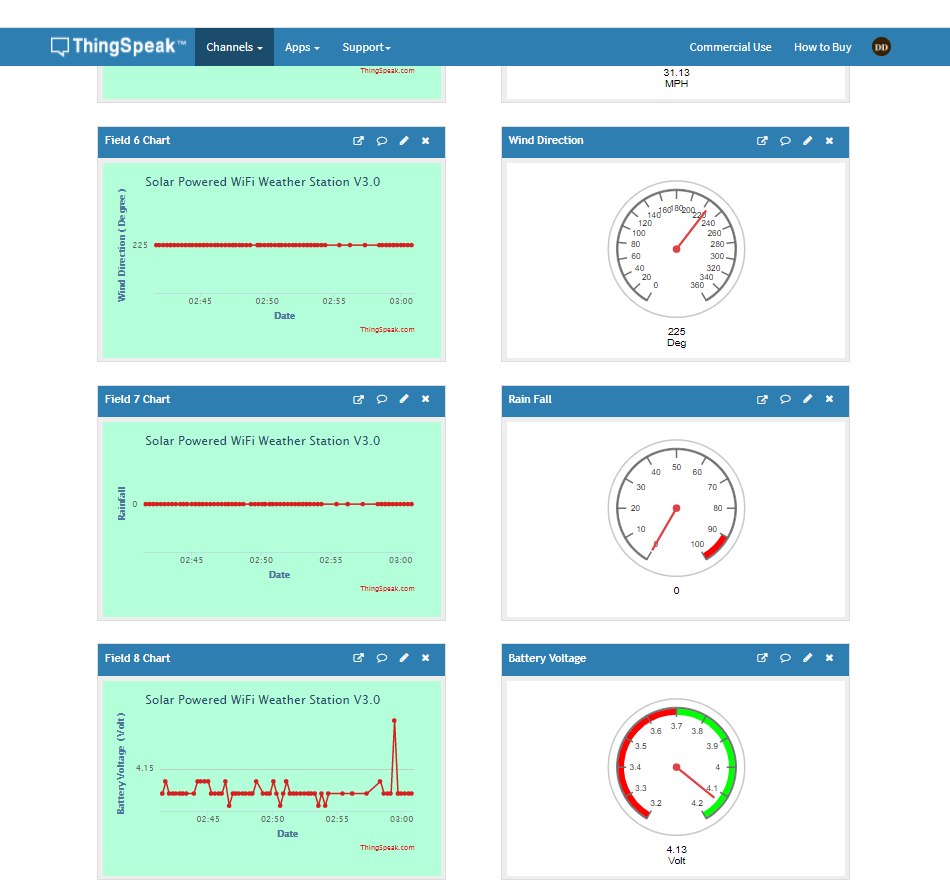
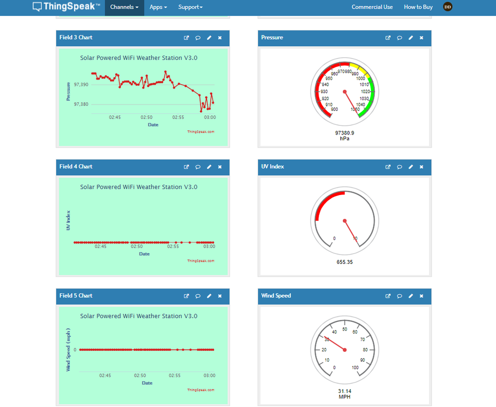
Uploading Sensor Data to ThingSpeak
10/07/2021 at 14:57 • 0 comments![]()
![]()
![]()
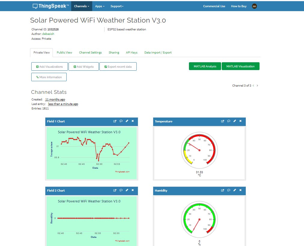
First, create an account on ThingSpeak.
Then create a new Channel on your ThingSpeak account.
Find How to Create a New Channel Fill Field 1 as Temperature, Field 2 as Humidity, Field 3 Pressure, Field 4 as UV Index, Field 5 as Wind Speed, Field 6 as Wind Direction, Field 7 as Rain Fall, and Field 8 as Battery Voltage
In your ThingSpeak account select “Channel” and then “My Channel”.
Click on your channel name.
Click on “API Keys” tab and copy the “Write API Key”
Open the Solar_Weather_Station_ThingSpeak code.
Replace the “WRITE API ”with the copied “Write API Key”.
-
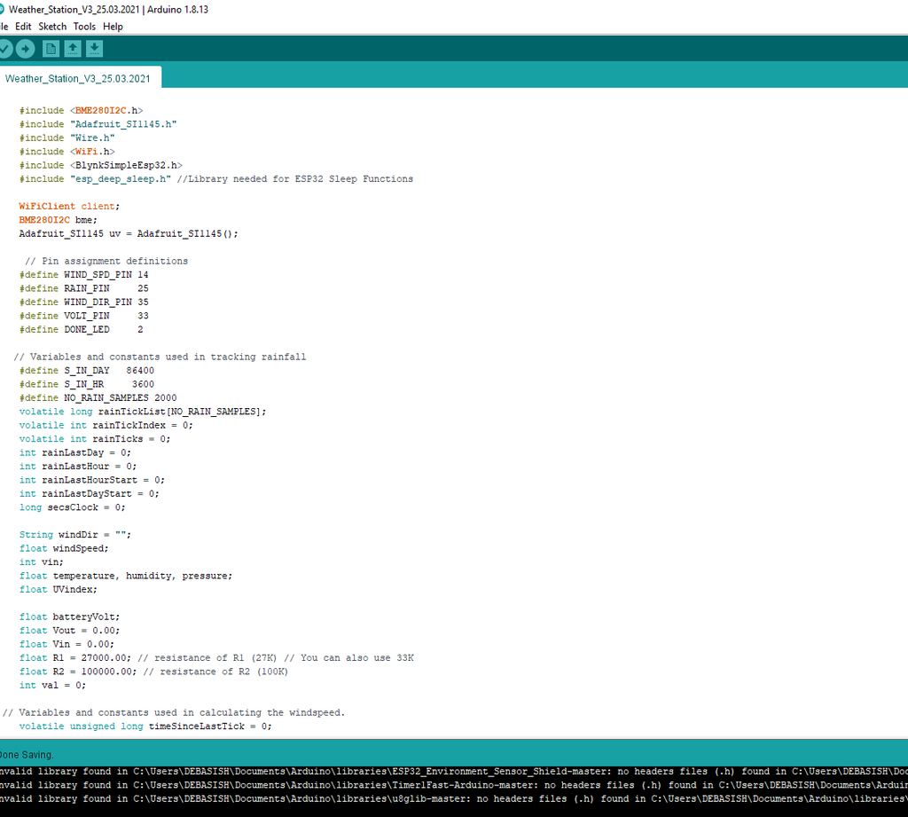
Software and Libraries
10/07/2021 at 14:54 • 0 comments![]()
![]()
![]()
To use the ESP32 board with the Arduino library, you'll have to use the Arduino IDE with ESP32 board support. If you haven't already done that yet, you can easily install ESP32 Board support to your Arduino IDE by following this tutorialby Sparkfun.
Install Libraries:
Before uploading the code install the following libraries :
1. ESP32
2.Blynk
3. BME280
5. BH1750
6. One Wire
Arduino Test Code:
//======================================================================================//
//                                                                                      //
//                 Solar WiFi Weather Station V3.0 Firmware                             //
//                                                                                      //
//             Developed by Debasish Dutta, Last Update: 30.03.2021                     //
//                                                                                      //
//======================================================================================//

    #include <BME280I2C.h>
    #include "Adafruit_SI1145.h"
    #include <BH1750.h>
    #include <DallasTemperature.h>
    #include <OneWire.h>
    #include "Wire.h"
    #include <WiFi.h>
    #include <BlynkSimpleEsp32.h>
    #include "esp_deep_sleep.h" //Library needed for ESP32 Sleep Functions

  //=================== Pin assignment definitions ==========================================

    #define WIND_SPD_PIN 14
    #define RAIN_PIN     25
    #define WIND_DIR_PIN 35
    #define VOLT_PIN     33
    #define TEMP_PIN 4  // DS18B20 hooked up to GPIO pin 4

  //=======================================================================================

    WiFiClient client;
    BME280I2C bme;
    Adafruit_SI1145 uv = Adafruit_SI1145();
    BH1750 lightMeter(0x23);
    OneWire oneWire(TEMP_PIN);
    DallasTemperature sensors(&oneWire);

  //=========================Declaring Variables and Constants ==================================


  // Variables used in reading temp,pressure and humidity (BME280)
    float temperature, humidity, pressure;

 // Variables used in reading UV Index (Si1145)
    float UVindex;

 // Variables used in reading Lux Level( BH1750 )
    float lux;

 // Variables used in calculating the windspeed
    volatile unsigned long timeSinceLastTick = 0;
    volatile unsigned long lastTick = 0;
    float windSpeed;

 // Variables used in calculating the wind direction
    int vin;
    String windDir = "";

 // Variables and constants used in tracking rainfall
    #define S_IN_DAY   86400
    #define S_IN_HR     3600
    #define NO_RAIN_SAMPLES 2000
    volatile long rainTickList[NO_RAIN_SAMPLES];
    volatile int rainTickIndex = 0;
    volatile int rainTicks = 0;
    int rainLastDay = 0;
    int rainLastHour = 0;
    int rainLastHourStart = 0;
    int rainLastDayStart = 0;
    long secsClock = 0;

 // Variables used in calculating the battery voltage
    float batteryVolt;
    float Vout = 0.00;
    float Vin = 0.00;
    float R1 = 27000.00; // resistance of R1 (27K) // You can also use 33K
    float R2 = 100000.00; // resistance of R2 (100K)
    int val = 0;

//=========================Deep Sleep Time ================================================

 //const int UpdateInterval = 1 * 60 * 1000000;  // e.g. 0.33 * 60 * 1000000; // Sleep time
 //const int UpdateInterval = 15 * 60 * 1000000;  // e.g. 15 * 60 * 1000000; // // Example for a 15-Min update interval 15-mins x 60-secs * 10000

 //========================= Enable Blynk or Thingspeak ===================================

 // configuration control constant for use of either Blynk or Thingspeak
 //const String App = "BLYNK";         //  alternative is line below
   const String App = "Thingspeak"; //  alternative is line above

 //========================= Variables for wifi server setup =============================

  // Your WiFi credentials.
  // Set password to "" for open networks.
  char ssid[] = "XXXX"; // WiFi Router ssid
  char pass[] = "XXXX"; // WiFi Router password

  // copy it from the mail received from Blynk
  char auth[] = "XXXX";

  // Thingspeak Write API
  const char* server = "api.thingspeak.com";
  const char* api_key = "XXXX"; // API write key

//========================= Setup Function ================================================

  void setup()
    {
      Serial.begin(115200);
      delay(25);
      Serial.println("\nWeather station powered on.\n");
      Wire.begin();
      sensors.begin();
  //  Wire.begin(22, 21); // for BH1750
      bme.begin(); // 0x76 is the address of the BME280 module
      uv.begin(0x60);  // 0x60 is the address of the GY1145 module
      wifi_connect();

      // Wind speed sensor setup. The windspeed is calculated according to the number
      //  of ticks per second. Timestamps are captured in the interrupt, and then converted
      //  into mph.
      pinMode(WIND_SPD_PIN, INPUT);     // Wind speed sensor
      attachInterrupt(digitalPinToInterrupt(WIND_SPD_PIN), windTick, FALLING);

      // Rain sesnor setup. Rainfall is tracked by ticks per second, and timestamps of
      //  ticks are tracked so rainfall can be "aged" (i.e., rain per hour, per day, etc)
      pinMode(RAIN_PIN, INPUT);     // Rain sensor
      attachInterrupt(digitalPinToInterrupt(RAIN_PIN), rainTick, FALLING);
      // Zero out the timestamp array.
      for (int i = 0; i < NO_RAIN_SAMPLES; i++) rainTickList[i] = 0;

     // ESP32 Deep SLeep Mode
     // esp_deep_sleep_enable_timer_wakeup(UpdateInterval);
     // Serial.println("Going to sleep now...");
     // esp_deep_sleep_start();
    }
//================================ Loop Function ==============================================

      void loop()
    {

     Read_Sensors_Data();  // Read all the Sensors
    // printdata();          // Print all the sensors data on the serial monitor
     Send_Data();          // Upload all the sensors data on the Internet ( Blynk App or Thingspeak )

    }

//============================ Connect to WiFi Network =========================================

void wifi_connect()
{
  if (App == "BLYNK")  // for posting datas to Blynk App
  {
    Blynk.begin(auth, ssid, pass);
  }
  else if (App == "Thingspeak")  // for posting datas to Thingspeak website
  {
     WiFi.begin(ssid, pass);

     while (WiFi.status() != WL_CONNECTED)
     {
            delay(500);
          //  Serial.print(".");
     }
     Serial.println("");
     Serial.println("WiFi connected");
  }
  else
  {
    WiFi.begin(ssid, pass);
    Serial.print(App);
    Serial.println(" is not a valid application");
  }

}

//===================================================================================================

//           Read Sensors Data ( BME280, Si1145,BH1750, Bat. Voltage, Wind Sensors, Rain Gauge )

//==================================================================================================


   void Read_Sensors_Data()
{
   // Reading BME280 sensor
    bme.read(pressure, temperature, humidity, BME280::TempUnit_Celsius, BME280::PresUnit_Pa);


 //***************************************************************************

 // Reading DS18B20 sensor
     sensors.requestTemperatures();


 //***************************************************************************
  // Reading GY1145 UV sensor

    UVindex = uv.readUV();
   // the index is multiplied by 100 so to get the
   // integer index, divide by 100!
      UVindex /= 100.0;
  //**********************************************************************************
 /*// Reading BH1750 sensor
  lux = lightMeter.readLightLevel();

  */
//**********************************************************************************
// Reading Battery Level in %
   val = analogRead(VOLT_PIN);//reads the analog input
   Vout = (val * 3.3 ) / 4095.0; // formula for calculating voltage out
   batteryVolt = Vout * ( R2+R1) / R2 ; // formula for calculating voltage in


//**********************************************************************************
// Read Weather Meters Datas ( Wind Speed, Rain Fall and Wind Direction )

      static unsigned long outLoopTimer = 0;
      static unsigned long wundergroundUpdateTimer = 0;
      static unsigned long clockTimer = 0;
      static unsigned long tempMSClock = 0;

      // Create a seconds clock based on the millis() count. We use this
      //  to track rainfall by the second. We've done this because the millis()
      //  count overflows eventually, in a way that makes tracking time stamps
      //  very difficult.
      tempMSClock += millis() - clockTimer;
      clockTimer = millis();
      while (tempMSClock >= 1000)
      {
        secsClock++;
        tempMSClock -= 1000;
      }

      // This is a once-per-second timer that calculates and prints off various
      //  values from the sensors attached to the system.
      if (millis() - outLoopTimer >= 2000)
      {
        outLoopTimer = millis();
        // Windspeed calculation, in mph. timeSinceLastTick gets updated by an
        //  interrupt when ticks come in from the wind speed sensor.
        if (timeSinceLastTick != 0) windSpeed = 1000.0/timeSinceLastTick;

       // Calculate the wind direction and display it as a string.
        windDirCalc();

     rainLastHour = 0;
     rainLastDay = 0;
  // If there are any captured rain sensor ticks...
     if (rainTicks > 0)
     {
      // Start at the end of the list. rainTickIndex will always be one greater
     //  than the number of captured samples.
      int i = rainTickIndex-1;

    // Iterate over the list and count up the number of samples that have been
    //  captured with time stamps in the last hour.
       while ((rainTickList[i] >= secsClock - S_IN_HR) && rainTickList[i] != 0)
          {
            i--;
            if (i < 0) i = NO_RAIN_SAMPLES-1;
            rainLastHour++;
          }

          // Repeat the process, this time over days.
          i = rainTickIndex-1;
          while ((rainTickList[i] >= secsClock - S_IN_DAY) && rainTickList[i] != 0)
          {
            i--;
            if (i < 0) i = NO_RAIN_SAMPLES-1;
            rainLastDay++;
          }
          rainLastDayStart = i;
        }
      }
   }


   // Keep track of when the last tick came in on the wind sensor.
    void windTick(void)
    {
      timeSinceLastTick = millis() - lastTick;
      lastTick = millis();
    }

    // Capture timestamp of when the rain sensor got tripped.
    void rainTick(void)
    {
      rainTickList[rainTickIndex++] = secsClock;
      if (rainTickIndex == NO_RAIN_SAMPLES) rainTickIndex = 0;
      rainTicks++;
    }

// reading wind direction
    void windDirCalc()
    {

  vin = analogRead(WIND_DIR_PIN);

  if      (vin < 150) windDir="202.5";
  else if (vin < 300) windDir = "180";
  else if (vin < 400) windDir = "247.5";
  else if (vin < 600) windDir = "225";
  else if (vin < 900) windDir = "292.5";
  else if (vin < 1100) windDir = "270";
  else if (vin < 1500) windDir = "112.5";
  else if (vin < 1700) windDir = "135";
  else if (vin < 2250) windDir = "337.5";
  else if (vin < 2350) windDir = "315";
  else if (vin < 2700) windDir = "67.5";
  else if (vin < 3000) windDir = "90";
  else if (vin < 3200) windDir = "22.5";
  else if (vin < 3400) windDir = "45";
  else if (vin < 4000) windDir = "0";
  else windDir = "0";
  }

 //======================  Print Data on Serial Monitor  ===============================================

  void printdata(){
   Serial.print("Air temperature [°C]: "); Serial.println(temperature);
   Serial.print("Humidity [%]: "); Serial.println(int(humidity));
   Serial.print("Barometric pressure [hPa]: "); Serial.println(pressure / 100);
   Serial.print("UV: "); Serial.println(UVindex);
 //  Serial.print("Light: ");  Serial.print(lux);  Serial.println(" lx");
   Serial.print("Windspeed: "); Serial.print(windSpeed*2.4); Serial.println(" mph");
   Serial.print("Wind dir: ");  Serial.print("  "); Serial.println(windDir);
   Serial.print("Rainfall last hour: "); Serial.println(float(rainLastHour)*0.011, 3);
 //  Serial.print("Rainfall last day: ");  Serial.println(float(rainLastDay)*0.011, 3);
 //  Serial.print("Rainfall to date: ");   Serial.println(float(rainTicks)*0.011, 3);
   Serial.print("Battery Level: "); Serial.println(batteryVolt);
   Serial.print("Temperature in C: ");   Serial.println(sensors.getTempCByIndex(0));    //print the temperature in Celsius
   Serial.print("Temperature in F: "); Serial.println((sensors.getTempCByIndex(0) * 9.0) / 5.0 + 32.0); //print the temperature in Fahrenheit

  }

//======================Upload Sensors data to Blynk App or Thingspeak =================================

void Send_Data()
{
// code block for uploading data to BLYNK App

  if (App == "BLYNK") { // choose application
   Blynk.virtualWrite(0,temperature );    // virtual pin 0
   Blynk.virtualWrite(1, humidity ); // virtual pin 1
   Blynk.virtualWrite(2, pressure/100 );    // virtual pin 2
   Blynk.virtualWrite(3, UVindex);    // virtual pin 3
  // Blynk.virtualWrite(4, windSpeed*1.492 ); // virtual pin 4
   Blynk.virtualWrite(4, windSpeed*2.4*4.5 ); // virtual pin 4
   Blynk.virtualWrite(5, windDir);    // virtual pin 5
   Blynk.virtualWrite(6, rainLastHour);    // virtual pin 6
   Blynk.virtualWrite(7, batteryVolt);    // virtual pin 7
   Blynk.virtualWrite(8, sensors.getTempCByIndex(0));    // virtual pin 8
   delay(12*5000);
  }

 // code block for uploading data to Thingspeak website

  else if (App == "Thingspeak") {
  // Send data to ThingSpeak
  WiFiClient client;
  if (client.connect(server,80)) {
  Serial.println("Connect to ThingSpeak - OK");
  Serial.println("");
  Serial.println("********************************************");
  String postStr = "";
  postStr+="GET /update?api_key=";
  postStr+=api_key;
  postStr+="&field1=";
  postStr+=String(temperature);
  postStr+="&field2=";
  postStr+=String(humidity);
  postStr+="&field3=";
  postStr+=String(pressure/100);
  postStr+="&field4=";
  postStr+=String(UVindex);
  postStr+="&field5=";
  //postStr+=String(windSpeed*1.492); //speed in mph
  postStr+=String(windSpeed*2.4*4.5); //speed in Km/h
  postStr+="&field6=";
  postStr+=String(windDir);
  postStr+="&field7=";
  postStr+=String(float(rainTicks)*0.011, 3);
  postStr+="&field8=";
  postStr+=String(batteryVolt);
  postStr+="&field9=";
  postStr+=String(sensors.getTempCByIndex(0));
  postStr+=" HTTP/1.1\r\nHost: a.c.d\r\nConnection: close\r\n\r\n";
  postStr+="";
  client.print(postStr);
  delay(5000);
 //*******************************************************************************

}
 while(client.available()){
    String line = client.readStringUntil('\r');
   // Serial.print(line);
  }
 }
}
//=============================End of the Program ================
Updated on 09.07.2021
My friend James is working hard to resolve the deep sleep issues, you may visit his GitHub repository for updates.
How to Install the Libraries?
You can read this tutorial by Sparkfun to install the Arduino libraries.
In my earlier version, there are two separate codes for Blynk and Thinspeak but in this version, we have written a single piece of code. The user has to only comment out a single line of code for Blynk or Thingspeak. For example, if you are using it for Blynk App, the code should be as below:
// configuration control constant for use of either Blynk or Thingspeak
// const String App = "BLYNK"; // alternative is line below
const String App = "Thingspeak";
// alternative is line above
Update On 19.08.2021 ( Deep Sleep Implementation by James )
James has written a new code for this project to implement deep sleep. You can find the code in his GitHub repository. The link is given below:
https://github.com/jhughes1010/weather
Steps to Install the New Software:
1. Download the code from the above GitHub link. Ensure you download from the MASTER branch. James is actively working on DEVELOP.
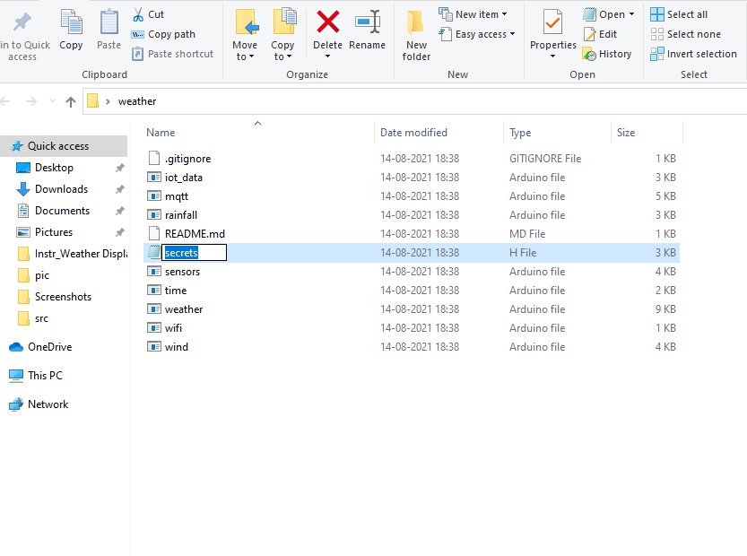
2. First, you have to unzip the downloaded code and then save it somewhere on your PC or Laptop. Remove the word master from the folder name, the final name shall be " weather "
3. Rename sec.h to secrets.h (this file contains WiFi details, API keys for internet data destinations, and configuration options ).
You can see the above images for your reference. The details on the software configuration are available here.
Credit: I would like to give special thanks to James who has worked hard to improve the software of this project.
-
3D Printed Enclosure
10/07/2021 at 14:49 • 0 comments![]()
The ideal enclosure for keeping the weather sensors is the Stevenson Screen. A Stevenson screen is an enclosure to shield meteorological sensors against precipitation and direct heat radiation from outside sources, while still allowing air to circulate freely around them.
My friend Glen from New Zealand helped me to make this professional-grade Stevenson Screen. I really appreciate his help in making this project successful.
This has a simple wall mount and a 2 part cover to isolate the heat transfer from the solar panel. The V3.0 design has a provision for mounting a UV Index sensor on the top. Apart from this, the top cover for mounting solar panel is kept away from the main enclosure to avoid heat transfer from the solar panel to the interior part of the enclosure.
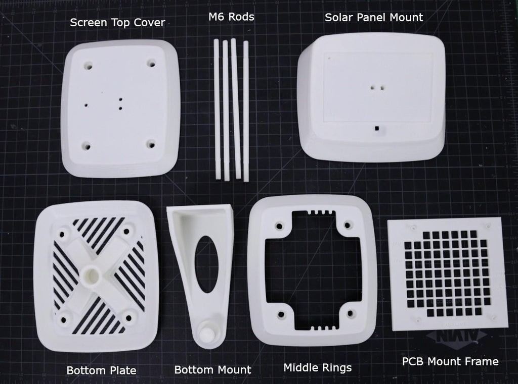
The Stevenson Screen has 6 parts:
1. PCB Mount Frame
2. Bottom Plate
3. Bottom Mount
4. Middle Rings x 12 Nos
5. Screen Top Cover
6. Top Cover for Solar Panel Mount ( Solar Panel Size: 110 x 69 mm )
7. M6 Rod x 4 Nos
I used my Creality 3D printer and 1.75 mm white PLA filament to print the parts. I will recommend using ABS or PTEG filament instead of using PLA.
You can refer to the above explosion diagram to assemble the 3D printed parts.
You can download the .STL files from Thingiverse
You can download the STEP files from GRABCAD for any modification.
-
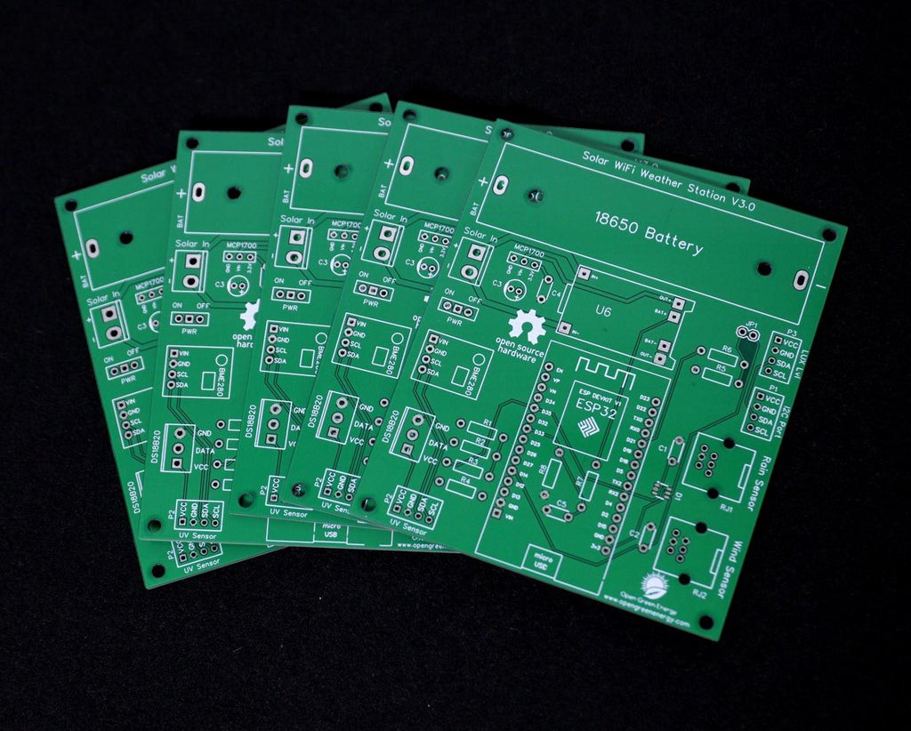
PCB Fabrication
10/07/2021 at 14:48 • 0 comments![]()
Once we are completed the PCB design we just need to click the “Gerber Output” button, save the project and we will be able to download the Gerber files which are used to manufacturing the PCB.
-
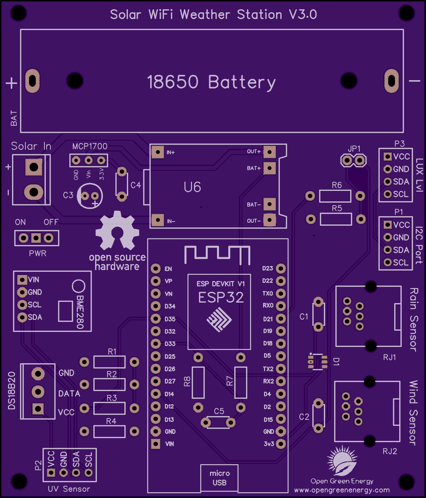
PCB Design
10/07/2021 at 14:47 • 0 comments![]()
![]()
![]()
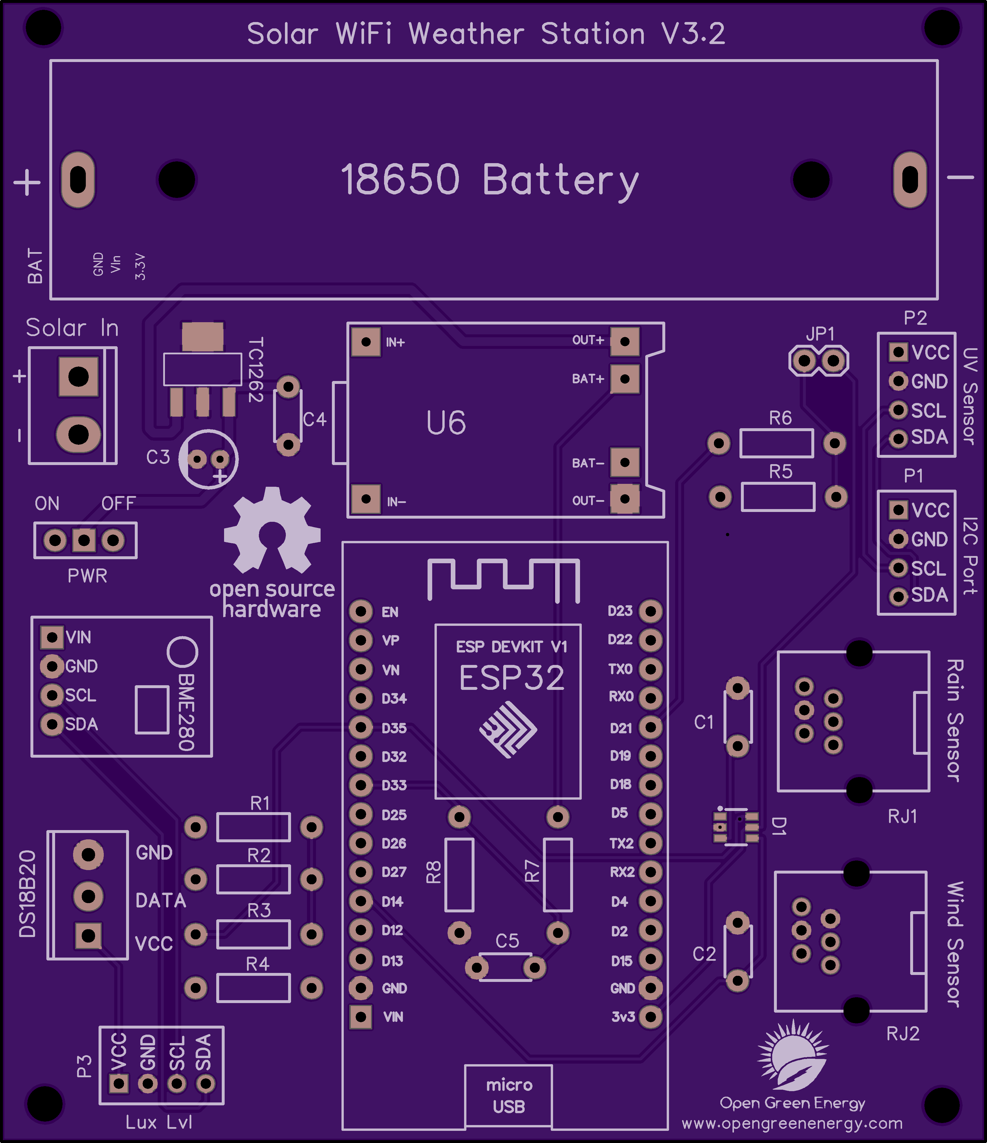
I have drawn the schematic by using EasyEDA online software after that switched to PCB layout.
All of the components you added in the schematic should be there, stacked on top of each other, ready to be placed and routed. Drag the components by grabbing on its pads. Then place it inside the rectangular borderline.
Arrange all the components in such a way that the board occupies minimum space. The smaller the board size, the cheaper will be the PCB manufacturing cost. It will be useful if this board has some mounting holes on it so that it can be mounted in an enclosure.
Now you have to route. Routing is the most fun part of this entire process. It’s like solving a puzzle! Using the tracking tool we need to connect all the components. You can use both the top and the bottom layer for avoiding overlap between two different tracks and making the tracks shorter.
You can use the Silk layer to add text to the board. Also, we are able to insert an image file, so I add an image of my website logo to be printed on the board. In the end, using the copper area tool, we need to create the ground area of the PCB. Now the PCB is ready for manufacturing.
You can order it from PCBWay
Note: When you place an order, I will get 10% donation from PCBWay for contribution to my work. Your little help may encourage me to do more awesome work in the future. Thank you for your cooperation.
Update On 24.05.2021
Now You can order the fully assembled PCB V3.0 from PCBWay. Please note that no sensors are included in the PCB, but you will get an ESP32 dev board and a Solar panel in the package.Update on 01.05.2021
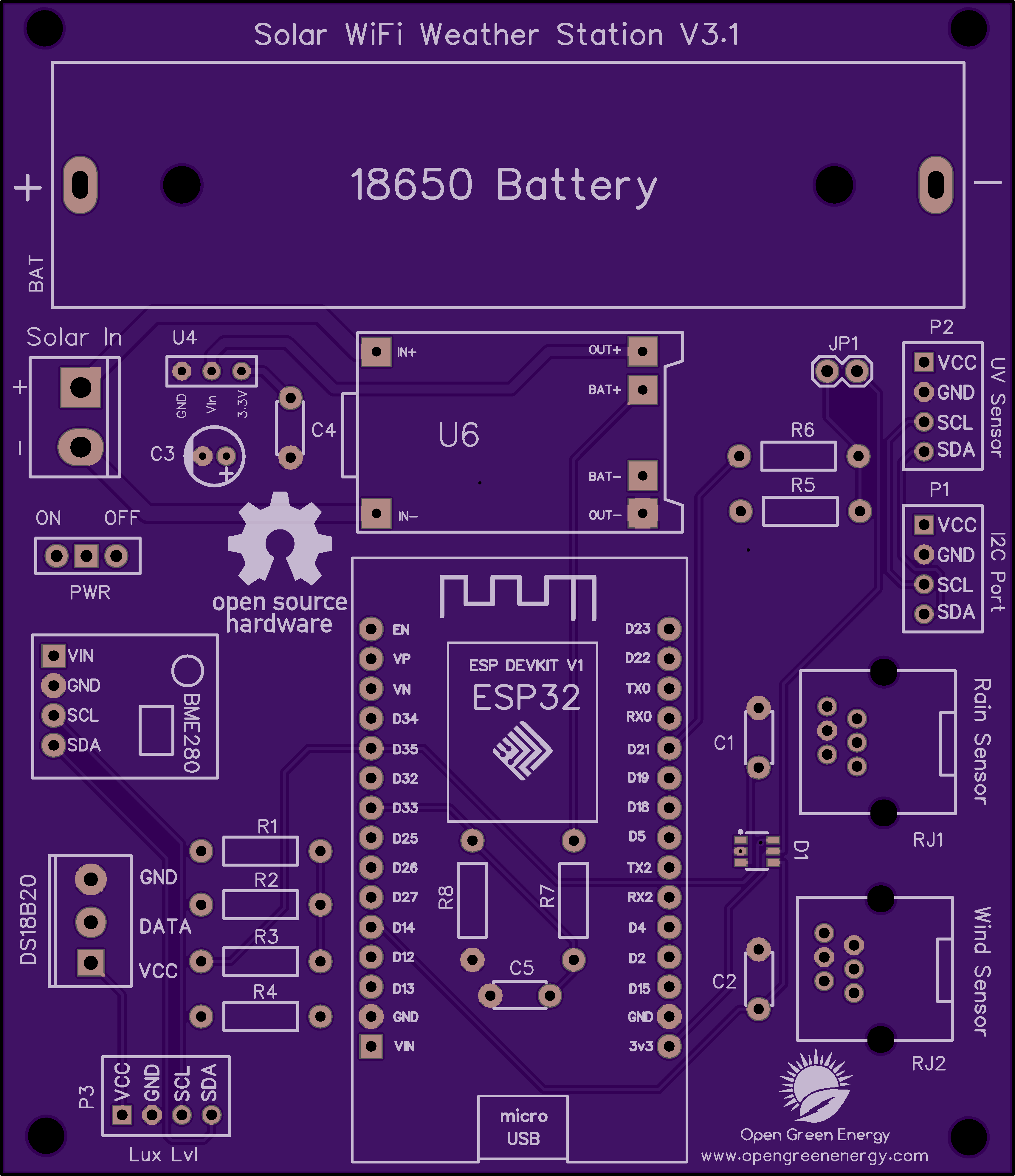
The PCB V3.0 is updated to V3.1, a small change in the I2C ports ( P1, P2, and P3 ) The sequence of pins are changed from ( VCC, GND, SDA, SCL ) to ( VCC, GND, SCL, SDA ) Note: The PCB V3.0 is working perfectly, but you need extension wires to connect the sensor modules in ports P1, P2, and P3.Update on 09.09.2021
The PCB V3.1 is updated to V3.2, upgrade from 200mA LDO ( MCP1700 ) to 500mA LDO ( TC1262-3.3V ) to make the power supply more stable. You can download the Gerber files or buy the PCB V3.2 from PCBWay
You can download the earlier Gerber files for PCB V3.0 and V3.1 from PCBWay.
-
Solar Panel Selection
10/07/2021 at 14:42 • 0 comments![]()
![]()
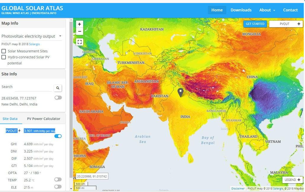
The amount of solar insolation varies according to which part of the globe you are located at. To find out the amount of solar insolation in your area, you can use the Global Solar Atlas. By taking consideration into a minimum of 1 hour of full sunlight, we are going to select the solar panel.
From the previous step, it is concluded that the average current consumption is 7.5 mA
Charge required for running the device for the whole day = 7.5 mA x 24 Hours = 180 mAh
So, our target is to generate 180 mAh in 1 hour.
To charge a 3.7V Li-Ion battery, a solar panel of voltage 5 to 6V is adequate.
Required Solar Panel rating = 180 mA at a voltage of around 5 to 6 volts.
Solar panel rating = 180 mA x 5V = 0.9 Watt, by considering some losses, I have selected a higher rating solar panel.
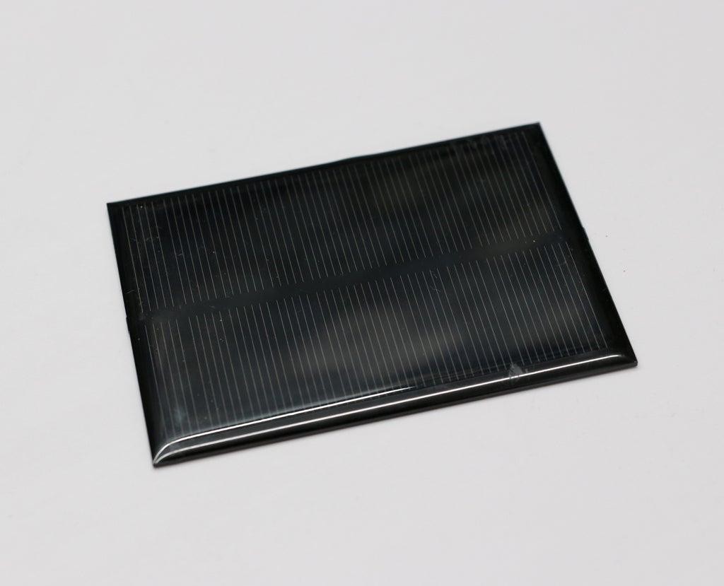
Solar Panel Selected: I have used a 5V,250mA Solar Panel ( 110 x 69 mm)
-
ESP32 - Thingspeak-Deep-Sleep
10/07/2021 at 14:39 • 0 comments![]()
The heart of our Weather Station is an ESP8266 SOC which is a power-hungry chip. When your project is powered by a plug-in the wall, you tend not to care too much about power consumption. But if you are going to power your project with batteries, every mA counts.
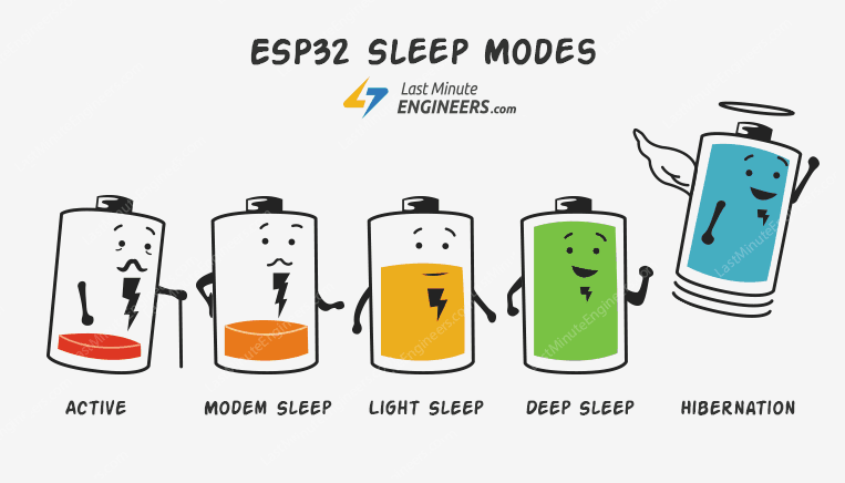
Our objective is to run the device by using a 18650 Li-Ion battery. To run the ESP32 by using a battery, we have to lower the power consumption. To do that, we’ll use the Deep Sleep Mode which is the most power-efficient option for the ESP chip. It allows to put the ESP32 into hibernation and saves the battery. You can wake up the ESP at regular intervals to make measurements and publish them.
Calculating Battery Life:
The ESP32 consumes around 75mA in normal operation and hits about 150mA while transmitting data over WiFi. and in Deep Sleep about 10uA. The ESP32 takes ~ 30secs to upload data.
Battery Life calculations:
Battery Used: 3400mAh / 3.7V 18650 Li-Ion
Publish Interval = 10mins ( ON Time: 30 sec and Sleep Time: 9 mins 30 sec )
Total number of Readings / Hour = 60/10 = 6
Power consumption per hour (ON time) = 6 x 150 mA * 30 / 3600 = 7.5mA
Sleep time = 6 x 10uA * 570 / 3600 = 0.0095 mA
Total time in hours on battery = 3400 / (7.5+0.0095) = 452.76Hrs
Total days on battery = 452.76/24 = 18.86 Days
I have prepared an excel sheet for calculating the battery life. It is attached below, you can use it.
Image Credit: lastminuteengineers.com
Solar Powered WiFi Weather Station V3.0
ESP32 based Open Source Weather Station