Open Green Energy
-
Monitoring Battery Voltage
10/07/2021 at 14:37 • 0 comments![]()
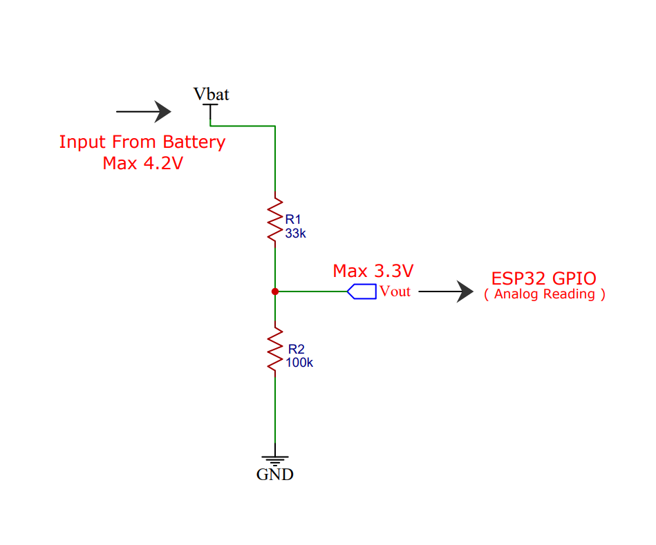
The weather station is run by a 18650 Li-Ion battery, so it is essential to monitor the battery status. The max voltage input to the ESP32 board is around 3.2~3.3V but a fully charged 18650 battery voltage is 4.2V. So to measure this voltage we have to step down the voltage by using a voltage divider network.
The voltage divider is made up of 27k (R1) and 100k (R2).
When you have your ESP32 powered with batteries or solar-powered as in this case, it can be very useful to monitor the battery level. One way to do that is to read the output voltage of the battery using an analog pin of the ESP32.
However, the battery we’re using here outputs a maximum of 4.2V when fully charged, but the ESP32 GPIOs work at 3.3V. So, we need to add a voltage divider so that we’re able to read the voltage from the battery.The voltage divider formula is as follows:
Vout = (Vbat*R2)/(R1+R2)
So, if we use R1=27k Ohm, and R2=100k Ohm,
We get: 1 Vout = (4.2*100k)/(27k + 100k) = 3.307V
So, when the battery is fully charged, the Vout outputs 3.307V that we can read with an ESP32 GPIO pin. To select the voltage divider resistance values, you can use this online calculator.
-
External Temperature Sensor
10/07/2021 at 14:36 • 0 comments![]()
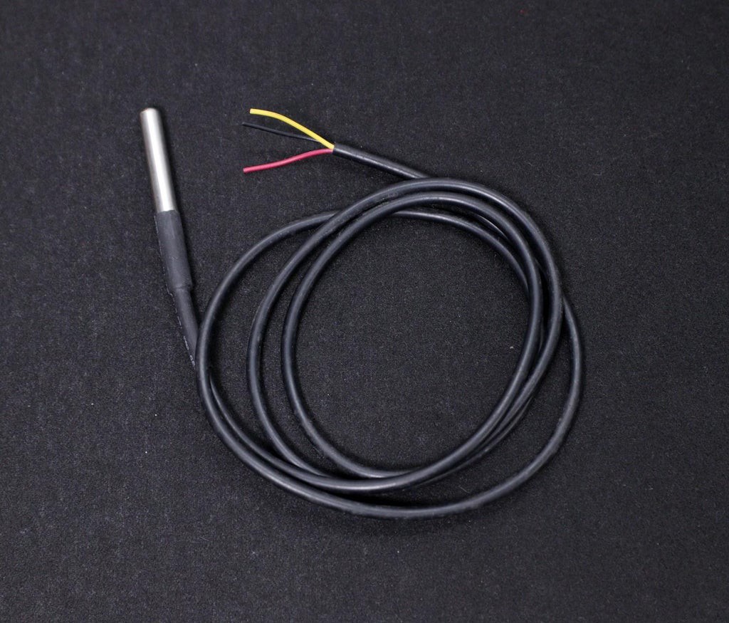
If you need, you can connect an external temperature sensor like DS18B20 to monitor the ambient temperature. DS18B20 is One Wire interface Temperature sensor manufactured by Dallas Semiconductor Corp. It requires only one digital pin for two-way communication with a microcontroller. I have hooked up this sensor with ESP32 GPIO pin4.
The DS18B20 comes usually in two form factors. One that comes in the TO-92 package looks exactly like an ordinary transistor and another one in a waterproof probe with an extension cable. I have used DS18B20 probe for measuring the temperature. It uses a one-wire protocol to communicate with the ESP32. It can be hooked up to the 3 pin screw terminal on the PCB.
To interface with the DS18B20 temperature sensor, you need to install the One Wire library and the Dallas Temperature library. You can read this articlefor more details on the DS18B20 sensor.
-
Monitoring Lux Level - BH1750 Sensor
10/07/2021 at 14:35 • 0 comments![]()
The BH1750 Ambient Light Sensor Module is based on the digital Ambient Light Sensor IC BH1750FVI developed by ROHM Semiconductor. It is a digital IC with built-in 16-bit illuminance to digital converter.
The output of this sensor is in LUX (lx), so it does not require any further calculations. Lux is the unit to measure Light intensity. It measures the intensity according to the amount of light hitting on a particular area. One lux is equal to one lumen per square meter.
For communication with external devices like ESP32, the BH1750 Ambient Light Sensor IC uses I2C Bus Interface.
Pin Description
VCC – 3.3V to 3.3VGND – VCC
SCL – SCL
SDA – SCL
ADD – I2C Device Address ( Kept Open )
You can read this instructable for information on BH1750 light sensor
-
Monitoring UV Index - SI1145 Sensor
10/07/2021 at 14:32 • 0 commentsThe Si1145 is a sensor with a calibrated UV sensing element that can calculate the UV Index. It can communicate via I2C communication (address 0x60). You can hook up this sensor with I2C port in the PCB which is located at the bottom left of the ESP board.
The SI1145 sensor really doesn’t have an actual UV sensor! Instead, it looks at the amount of visible and IR light it receives from the Sun and uses a formula to calculate the UV index, right down to two decimal points.
You can read this article to know more about the UV sensor.
If you need a more accurate measurement of UV Index, you may use the VEML6070 sensor. Unlike the Si1145, this sensor will not give you UV Index readings. However, the Si1145 does UV Index approximations based on light level, not true UV sensing. The VEML6070 in contrast does have a real light sensor in the UV spectrum.
You can read this tutorial for writing the code and using its library.
-
Monitoring Pressure ,Temperature and Humidity by BME280
10/07/2021 at 14:32 • 0 comments![]()
In the earlier days, weather parameters like ambient temperature, humidity, and barometric pressure were measured with separate analog instruments: thermometer, hygrometer, and barometer. But today the market is flooded with cheap and efficient digital sensors that can be used to measure a variety of environmental parameters. The best examples are sensors like DHT11, DHT 22, BMP180, BMP/E280, etc.
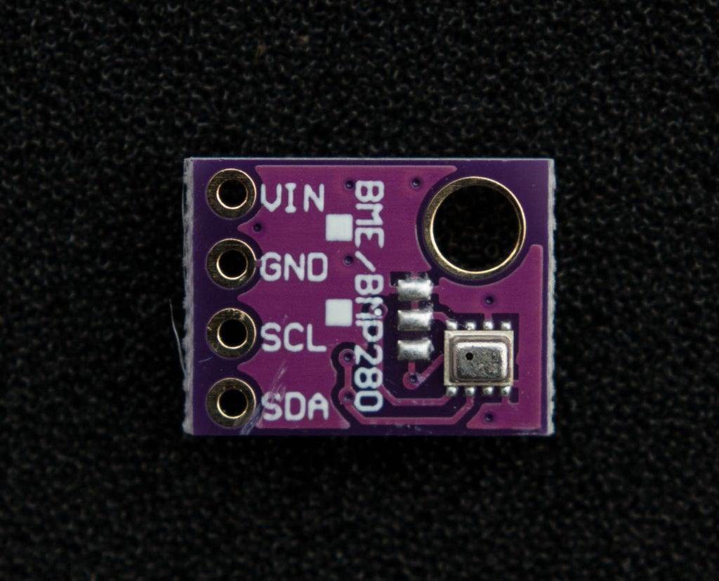
In this project, we will use BMP280 / BME280 sensor.
BMP280: BMP280 is a sophisticated sensor that very accurately measures barometric pressure and temperature with reasonable accuracy. The BME280 is the next generation of sensors from Bosch and is the upgrade to the BMP085/BMP180/BMP183 - with a low altitude noise of 0.25m and the same fast conversion time. The advantage of this sensor is that it can use either I2C or SPI for communication with the microcontroller. For simple easy wiring, I will suggest buying the I2C version board.
BME280: The new BME280 sensor, an environmental sensor with temperature, barometric pressure, and humidity. The BME280 is the next generation of sensors from Bosch and is the upgrade to the BMP280. This precision sensor from Bosch is the best low-cost sensing solution for measuring humidity with ±3% accuracy, barometric pressure with ±1 hPa absolute accuracy, and temperature with ±1.0°C accuracy. It can be used in both I2C and SPI.
Note: BME280 can measure humidity but BMP280 can't. In the market, BMP280 is also available by the name of BME280. So be sure whether it is a BMP280 or BME280.
You can read this nice article on BME280 for a better understanding.
-
Rain Gauge ( Rain Fall Sensor )
10/07/2021 at 14:25 • 0 comments![]()
![]()
![]()
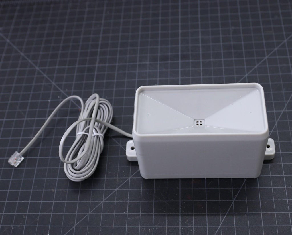
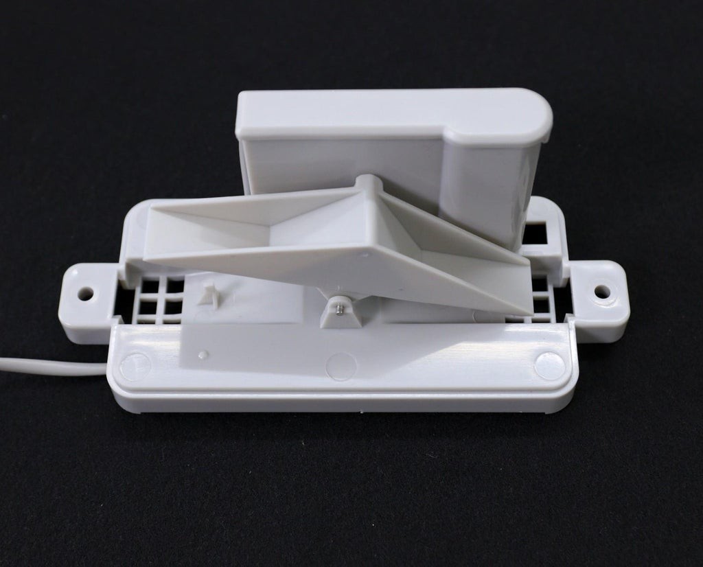
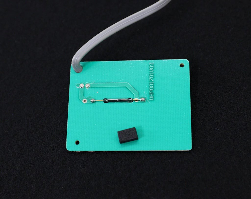
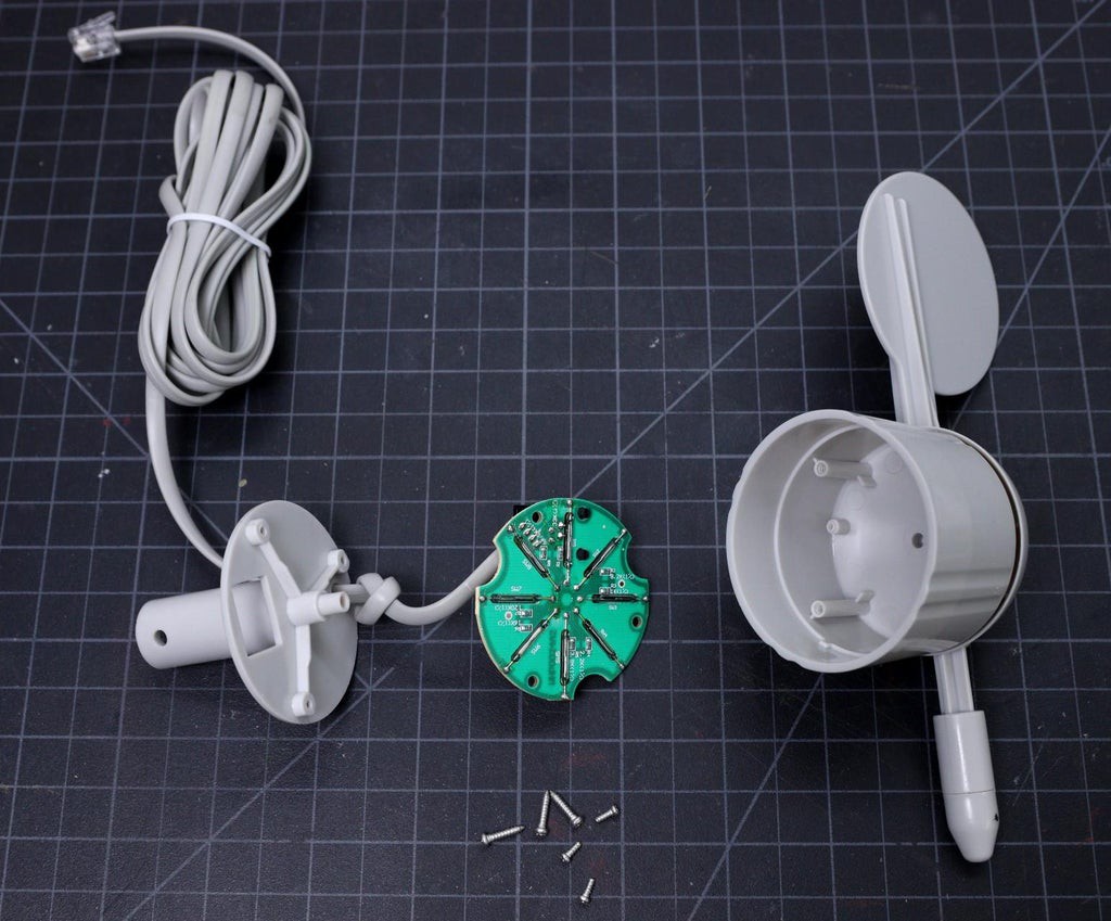
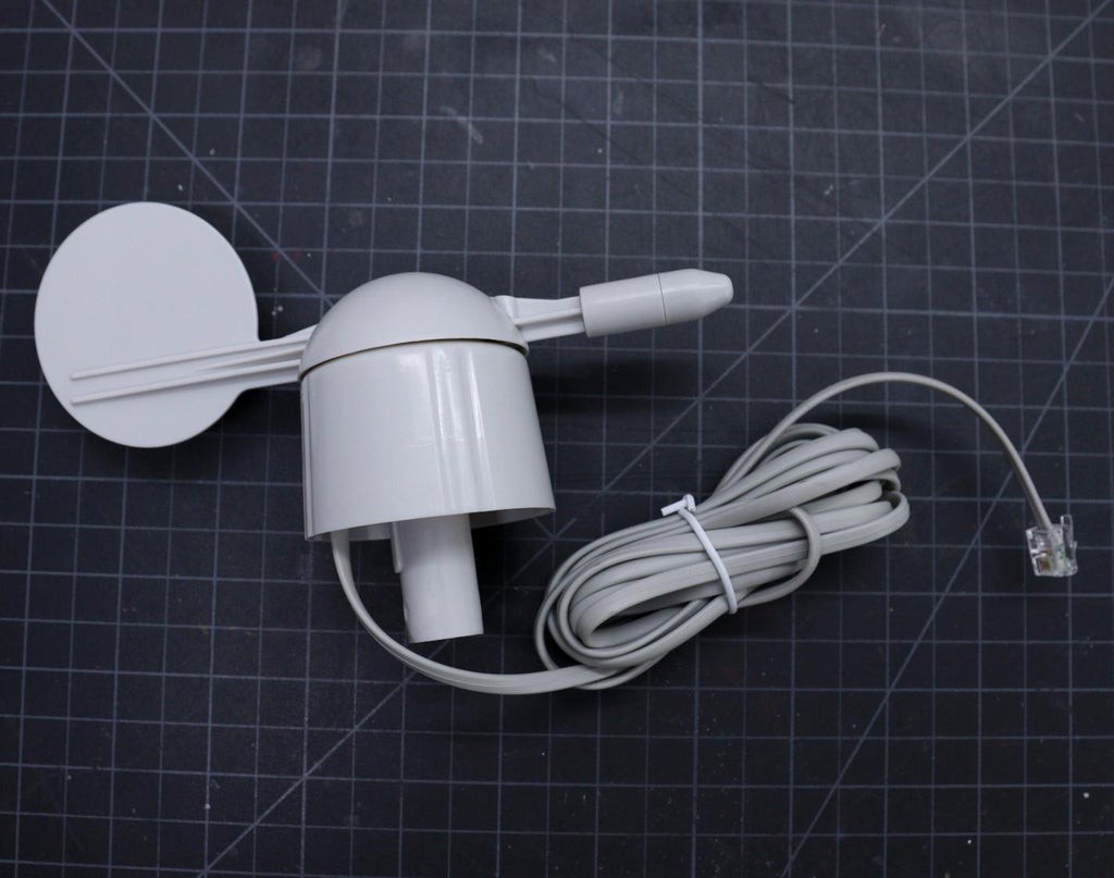
Here I have used a most common type of Rain Sensor which is called a Tipping Bucket rain gauge. Basically, there's a little see-saw shape tipper bucket inside the sensor ( see the above picture ). The rain fills up a bucket on one end and it tips over so that it empties and the bucket on the other side starts to fill. Each time the bucket tips it passes a magnet over a reed switch making a momentary electrical connection. The buckets are calibrated to a volume of water, which means if we can count how many times the switch closes we can calculate how much rainfall there's been.
Much like the wind speed gauge, the rainfall gauge generates ticks to tally the amount of rain that has fallen. Count ticks to determine how much rain has fallen recently. Each tick represents 0.011" ( 0.28mm ) of rainfall. This sensor is connected to pin 25 of the ESP32.
The rain gauge that I have used here is from Sparkfun. It has an RJ-11 plug on the end, you can directly plug it into the Weather Station V3.0 PCB.
You can make your 3D printed Rain Gauge by following this article
Measuring the Rainfall:
In the previous step, we have discussed that each time the bucket tips, it passes a magnet over a reed switch making a momentary electrical connection. Here each tip of the bucket in the rain gauge can be assumed as a button press. We can easily then connect the gauge as if it were a button.
The rain gauge is connected to the ESP GPIO pin 25 and GND. After that, all we need to do then is to monitor for button presses which are pretty straightforward. We can use the pin interrupts method to monitor the button press ( tips). When the reed switch closes the circuit (pressing the button, the bucket tipping), it triggers a software event.
Here I am using attachInterrupt()to monitor the number of tips. You can find the details from ArduinoPage.
-
Anemometer ( Wind Speed Sensor)
10/07/2021 at 14:24 • 0 comments![]()
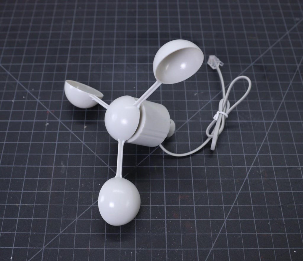
The wind speed sensor is a cup-type anemometer measures wind speed by closing a contact as a magnet moves past a reed switch. As per the datasheet, a wind speed of 2.4km/h (1.4912 mph) causes the switch to close once per second. The anemometer switch is connected to the inner two conductors of the RJ 11 cable shared by the anemometer and wind vane (pins 2 and 3).
The Anemometer is connected to the ESP32 GPIO pin 14 and GND. After that, all we need to do then is to monitor for button presses which is pretty straightforward. We can use the pin interrupts method to monitor the button press ( tips). When the reed switch closes the circuit (pressing the button), it triggers a software event.
If you want to make your own wind sensor, then read this nice Instructable
These are few more 3D printed Wind Sensors:
-
Wind Vane ( Wind Direction Sensor)
10/07/2021 at 14:23 • 0 comments![]()
![]()
![]()
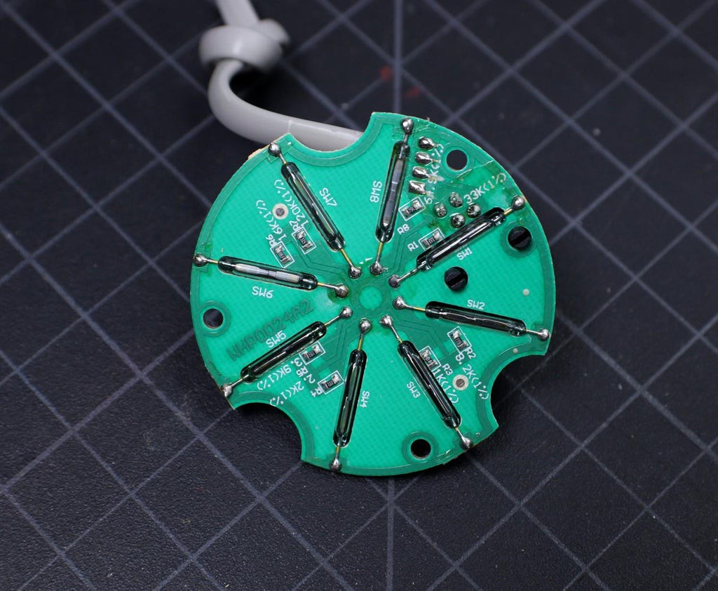
The wind vane indicates the direction that the wind is blowing. It is the most complex of the sensors in the Sparkfun Weather Sensor Kit. It has eight reed switches, each connected to a different resistor. As the wind vane rotates, a magnet closes the reed switches and may close two at a time due to their proximity to each other, allowing up to 16 different positions to be indicated. However, in testing the unit, I never could make the device close two switches at once, so although it might be possible theoretically to measure 16 directions, I only get eight. The software takes 16 directions into account, just in case.
An external resistor can be used to form a voltage divider, producing a voltage output that can be measured with an analog to digital converter, on your the microcontroller allows you to determine the direction of the wind vane pointer.
To measure voltage output, I have used a 10kohm external resistor to form a voltage divider with the wind vane resistor ( Rvane). The 10K resistor is connected to 3.3V as shown in the above figure. Then, I connect the middle of the divider to the ESP32 ADC pin (GPIO 35), measure the voltage, and by referring to the table shown above, convert to the wind direction.
The reed switches and resistors arrangement are shown in the above picture. Resistance values for all 16 possible positions are given in the table.
When the wind vane pointer falls in between two switches, the resistance value is considered as the equivalent resistance between the two adjacent resistances. In this situation, the vane’s magnet activates two switches simultaneously, as result they are connected in parallel.
Example:
When the wind vane pointer falls in between the Switches S1 and S2, the equivalent resistance is determined by the following formula:
Rvane = R1x R2 / ( R1+R2 ) = 33 x 8.2 / ( 33 +8.2 ) = 6.57K
Since the values outputted by the wind vane are based on degrees, you can, in theory, have any value represent any direction. However, it is recommended to have the value at degree 0 represent North for ease of use.
-
Selecting the Power Supply
10/07/2021 at 13:55 • 0 comments![]()
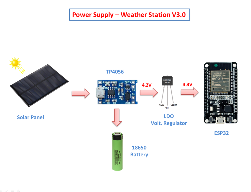
If you are planning to install the weather station at a remote location like your farmhouse, you may not get access to the power grid to run the weather station. To run the station continuously, there must be a continuous power supply otherwise the system will not work. The best way to provide continuous power to the circuit is by using a battery. But in the case of the battery, after some days of run, its juice will run out, and it is a really difficult job to go there and charge it. So a solar charging circuit was proposed to use free energy from the sun to charge the battery and to power the ESP32 board.
Here, I have used a 18650 Li-Ion battery. The battery is charged from a Solar panel through a TP4056 charging module. The TP4056 module comes with a battery protection chip or without the protection chip. I will recommend buying a module that has a battery protection chip included.
The 18650 battery outputs 4.2V when fully charged. The battery voltage is further step down to 3.3V by using a low dropout voltage regulator(MCP1700-3302E).
The output from the voltage regulator will power the ESP32 through the 3.3V pin.
Power Supply Circuit:
![]()
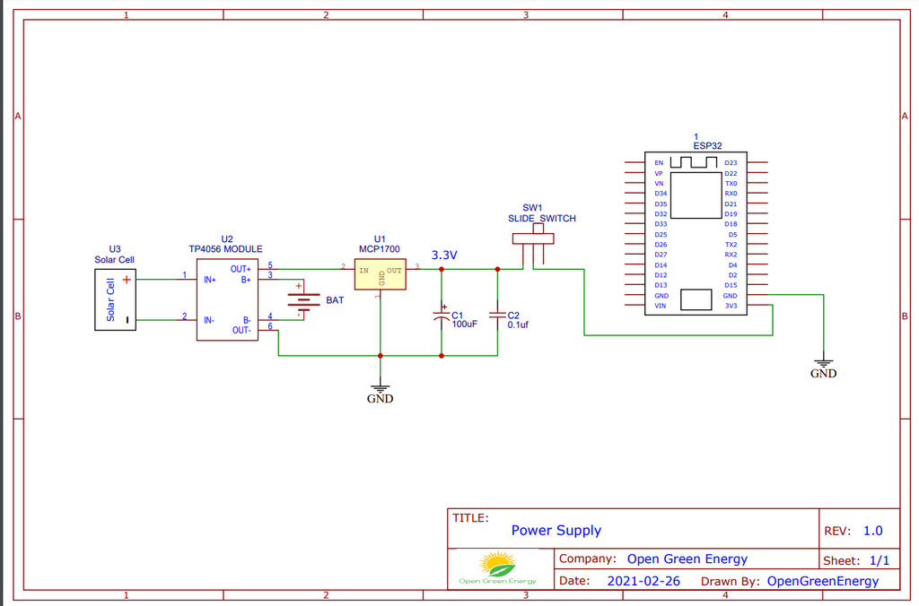
The operating voltage of the ESP32 is 3.3V whereas the fully charged battery voltage is 4.2V. So we have to step down the battery voltage from 4.2V to 3.3V, which can easily be done by a linear voltage regulator but unfortunately, it is not at all recommended for this project. Because all the linear regulators require an input voltage at least some minimum amount higher than the desired output voltage. That minimum amount is called the dropout voltage. Due to this reason when battery voltage drops to around 3.7V, the linear voltage regulator will not able to maintain the voltage required voltage ( 3.3V ).
The solution to the above problem is to use a low-dropout or LDO regulator. A low-dropout or LDO regulator is a DC linear regulator which can regulate the output voltage even when the supply voltage is very close to the output voltage. Here we will use an MCP1700 LDO for efficiently powering the Circuit.
A ceramic capacitor ( 0.1uF) and an electrolytic capacitor (100uF) are connected in parallel to the GND and Vout pin of the LDO ( MCP1700 -3.3V ) to smooth the voltage peaks.
The output of the MCP1700 is connected to the ESP32 3.3V pin through a slide switch.
Solar Powered WiFi Weather Station V3.0
ESP32 based Open Source Weather Station