-
Solution #1: ADAS - CAS - Tweaking for Indian Conditions
10/24/2021 at 16:56 • 0 commentsAfter trying out the assembled gadget for vehicles and people on the road, I wanted to tweak the solution to cater the solution for the Indian situation. The Indian traffic conundrum is so unique that it demands custom solutions. To start with, we need to train object detection models with Indian vehicles such as trucks, tempos, vans, autos, cycle rickshaws, etc.
Further, to enhance smart surround view, we need to train the model with Indian traffic signs and signboards to give more meaningful driver-assist warnings on Indian roads. It's a common sight in India, the animals like cows, pigs, buffaloes, goats, dogs, etc., cross the roads and highways. Hence, it's beneficial to detect them as well.
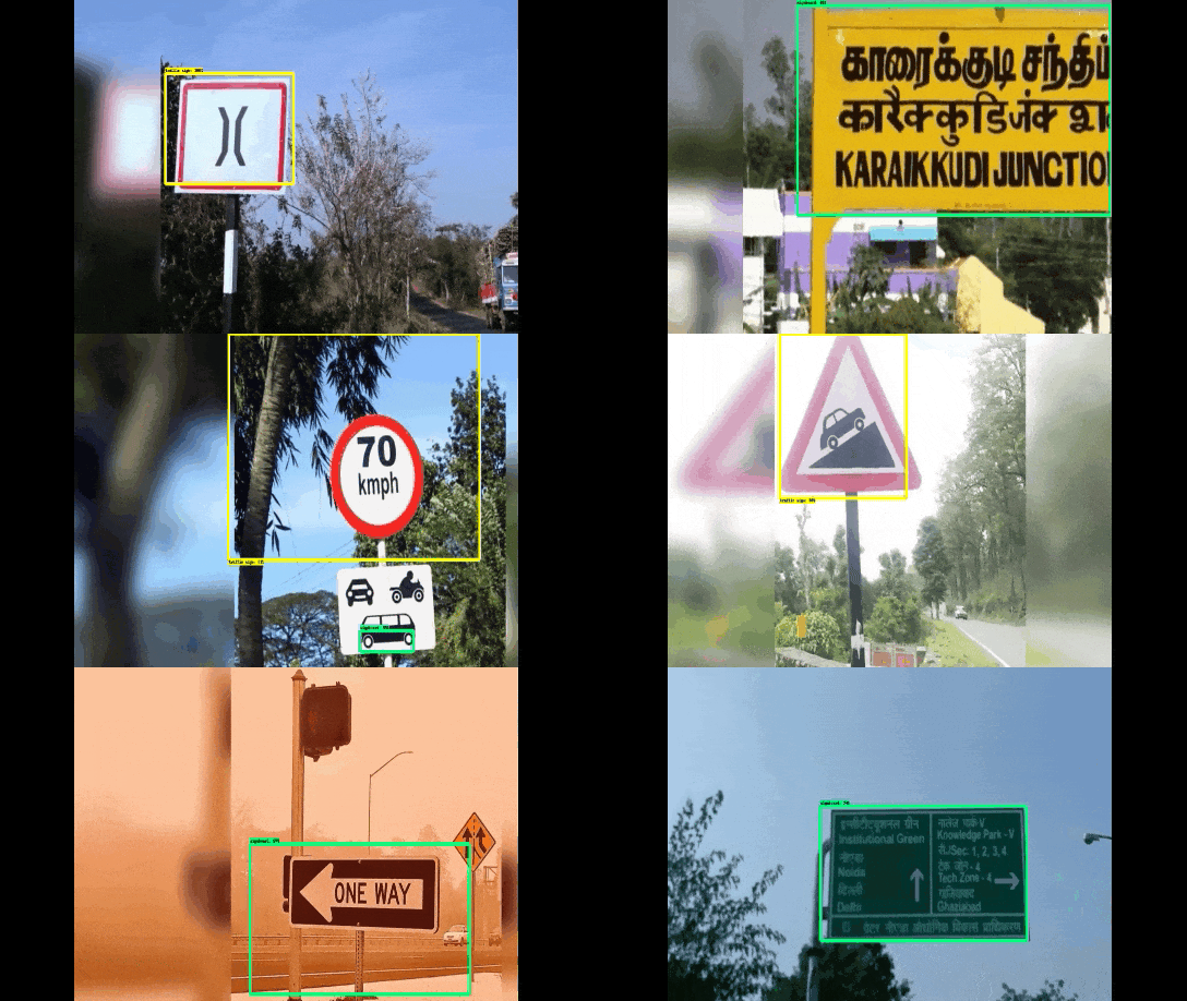
For the PoC, see the output of SSD-Mobilenet model trained to classify Indian traffic signs against Indian signboards. You can further classify the traffic sign to decipher the exact meaning of the sign.
![trafficSign.gif trafficSign.gif]()
SSD-MobileNet model able to classify Indian Traffic Signs (Yellow Bbox) vs Sign Boards (Green Bbox) The annotated Indian Traffic Sign dataset is provided by Datacluster Labs, India. They are yet to finish the annotation of "Indian Vehicles" database. It's just a matter of training time to make this gadget, tailor-made for India.
To find out the ROI from images, we have used SSD MobileNet trained on COCO filtered by potential objects. To detect only people and vehicles, you can use this model also to get better speed and accuracy. More importantly, the core task of custom object training and its deployment on IoT devices and Android mobiles are handled at depth in Solution #5.
The output of this model is sent from Node 1 to Node 2, where the LiDAR-Camsensor fusion happens, further pushing a message to Node 3. For the system to function, the 3 MQTT nodes should work in tandem, orchestrated by MQTT messages, published, and subscribed on respective topics.
# Sensor Fusion happens at Node 2 def on_message(client, userdata, msg): word = msg.payload.decode() # objAttributes contains label, # theta min and max separated by | objAttributes = word.split('|') now = time.localtime() if (now.tm_min * 60 + now.tm_sec - int(objAttributes[3]) >= 1): return theta1 = float(objAttributes[1]) theta2 = float(objAttributes[2]) dist = getObjectDistance(int(theta1) + 90 + 59, int(theta2) + 90 + 59) # convert distance from mm to cms dist = round(float (dist / 1000), 1) theta_mid = int((theta1 + theta2) / 2) # if near then announce an alert! # Passing the hue value on MQTT. 0 = Red. 0.3 = Green if (dist < 2.0): announceText = "ALERT ALERT " client.publish("object/flashlight", "0.0") else: announceText = "" client.publish("object/flashlight", "0.3") -
Implementation of 2D LIDAR-Camera Sensor Fusion
10/24/2021 at 16:48 • 0 commentsAfter doing 3D LIDAR-Camera Sensor Fusion, we need to do the mathematical variation for 2D, as the assembled gadget is equipped with 2D RP LIDAR A1 to minimize the cost.
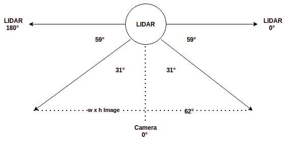
2D LIDAR scans the environment in a 2D plane, orthogonal to the camera plane. The rotating scan will estimate the distance to the obstacle, for each angle from 0° to 360°. Due to the placement of LIDAR w.r.t. Pi Cam in the gadget, the camera is at +90° on the LIDAR geometry. However, note that the Field of View of Pi cam V2 is 62°x48° in horizontal x vertical direction respectively.
The integrated front view of the device is as shown below.
![image.png image.png]()
LIDAR-Camera Geometry As both the LIDAR and Camera sensor data is available in the frontal 62° arc, we need to fuse the data. In the LIDAR scan plane, the camera data starts from +59° to +59° + 62° = 121°. We can run object detection on the image to get bounding boxes for the objects of interest. Eg: human, car, bike, traffic light, etc. Since 2D LIDAR has only width information, consider only the x_min and x_max of each bounding box.
We need to compute the LIDAR angle corresponding to an image pixel, in order to estimate the distance to the pixel. To find the distance to the object inside the bounding box, compute θ_min and θ_max corresponding to x_min & x_max using the below formula, based on the above diagram,
![image.png image.png]()
w = Image Width. Apply the same formula for θ_max also Now you can find the distance to each angle between θ_min and θ_max based on the latest LIDAR scan data. Then compute the median distance of all LIDAR points that subtends the object bounding box to estimate the object depth. If the distance is below a threshold, then trigger a warning based on the angle. Repeat warning, if the box center shift by a significant distance in subsequent frames.
for detection in detections: if detection.score > threshold: class_id = int(detection.id)-1 # Potential Objects: person, bicycle, car, bus, # truck, traffic light, street sign, stop sign if class_id not in [0, 1, 2, 3, 5, 7, 9, 11, 12]: continue det_label = labels[class_id] if labels and len(labels) >= class_id else '#{}'.format(class_id) xmin = max(int(detection.xmin), 0) ymin = max(int(detection.ymin), 0) xmax = min(int(detection.xmax), x_width) ymax = min(int(detection.ymax), y_height) x_mid = np.mean([xmin, xmax]) y_mid = np.mean([ymin, ymax]) if not isAnnounced(det_label, x_mid, y_mid): # theta min and max corresponds to Pi cam FoV angle # Picam has 62 degrees horizontal FoV. Need to # convert to LIDAR angles at LIDAR node. theta_min = xmin / (x_width / 62) + 59 theta_max = xmax / (x_width / 62) + 59 now = time.localtime() client.publish("object/getdistance", str(det_label) + '|' + str(theta_min) + '|' + str(theta_max) + '|' + str(now.tm_min * 60 + now.tm_sec)) objectsInFrame.append(det_label) objectMidPts.append((x_mid, y_mid)) # List of objects and its mid points in last 30 frames will be stored in dqueue if len(objectsInFrame) > 0: objLastFrames.extend([objectsInFrame]) objMidsLastFrames.extend([objectMidPts]) noObjFrames = 0 else: noObjFrames += 1 # If no objects found in last 30 frames, reset the queue if noObjFrames >= 30: objMidsLastFrames.clear() objLastFrames.clear() noObjFrames = 0 -
Derivation and Implementation of 3D LIDAR-Camera Sensor Fusion
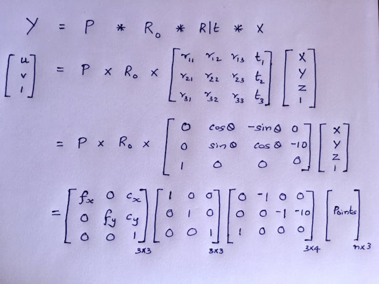
10/24/2021 at 15:11 • 0 commentsTo do LIDAR-Camera Sensor fusion, we need to do rotation, translation, stereo rectification, and intrinsic calibration to project LIDAR points on the image. We will try to apply the fusion formula based on the custom gadget that we built.
From the physical assembly, I have estimated the Pi Cam is 10 mm below the LIDAR scan plane. i.e. a translation of [0, -10, 0] along the 3D-axis. Consider Velodyne HDL-64E as our 3D LIDAR, which requires 180° rotation to align the coordinate system with Pi Cam. We can compute the R|t matrix now.
As we use a monocular camera here, the stereo rectification matrix will be an identity matrix. We can make the intrinsic calibration matrix based on the hardware spec of Pi Cam V2.
![3D_visual_fusion.jpg 3D_visual_fusion.jpg]()
Instead of 1 point, we can feed in ‘n’ points For the RaspberryPi V2 camera,
- Focal Length = 3.04 mm
- Focal Length Pixels = focal length * sx, where sx = real world to pixels ratio
- Focal Length * sx = 3.04mm * (1/ 0.00112 mm per px) = 2714.3 px
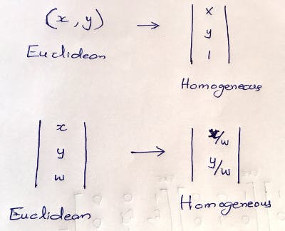
Due to a mismatch in shape, the matrices cannot be multiplied. To make it work, we need to transition from Euclidean to Homogeneous coordinates by adding 0's and 1's as the last row or column. After doing the multiplication we need to convert back to Homogeneous coordinates.
![Eucli2Homo.jpg Eucli2Homo.jpg]()
Conversion to and from Euclidean to Homogeneous
You can see the 3DLIDAR-CAM sensor fusion projection output after applying the projection formula on the 3D point cloud. The input sensor data from 360° Velodyne HDL-64E and camera is downloaded [9] and fed in.![Sensor_Fusion_Output.gif Sensor_Fusion_Output.gif]()
Sensor Fusion Projection Output: Green (Near) & Red (Far) However, the 3D LiDAR cost is a barrier to building a cheap solution. We can instead use cheap 2D LiDAR with necessary tweaks, as it only scans a single horizontal line.
-
Hardware Assembly: ADAS - Collision Avoidance System (CAS)
10/24/2021 at 15:02 • 0 commentsReal-World Implementation with RPi and RPLIDAR A1
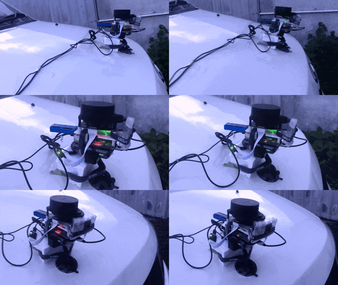
First, assembled the Pi with RPLIDAR A1, Pi Cam, LED SHIM, and NCS 2. 2D LIDAR is used instead of 3D LIDAR as we aim to make the gadget, cheapest possible. The unit is powered by a 5V 3A 10, 000 mAH battery.
Connected RPLIDAR A1 with the USB adapter that is connected to the Pi USB using a micro-USB cable. LIDAR's adapter provides power and converts LIDAR's internal UART serial interface to a USB interface. Use an Aux-to-Aux cable to connect RPi to speakers.Due to physical constraints, an LED SHIM is used instead of Blinkt to signal warning messages. While the total cost of the ADAS gadget is just around US$ 150-200, one may have to shell out at least $10-20K more, to get a car model with such advanced features.
![adas.gif adas.gif]()
ADAS Device mounted on car bonnet First, I tried to solve 3D LIDAR-Camera Sensor Fusion on the above gadget. Just imagine, a 3D LIDAR is connected the same way as above. Further, I thought to do the variation for 2D LIDAR-Camera Fusion, to make it work on RPLIDAR A1 as the multi-layer laser scan in 2D LIDAR is different from 3D LIDARs.
-
3D Printing Custom Part for Solution #1: ADAS - CAS
10/24/2021 at 14:39 • 0 commentsFor Solution #1: ADAS - Collision Avoidance System (CAS):
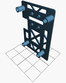
For the need of assembly, a LIDAR mount had to be 3D printed so that RPi can be attached to LIDAR and mounted on a car. Part of the mount design is taken from the STL files obtained from here. The design file is attached along with the files so that you can easily rebuild the project. 3D Printing of this custom part is the first step done before doing the physical assembly.
![image.png image.png]()
STL Visualization: LIDAR Mount for Raspberry Pi
Note that this solution is a sequel to my project "Self Driving Car on Indian Roads" (Blog here)
Multi-Domain Depth AI Usecases on the Edge
SLAM, ADAS-CAS, Sensor Fusion, Touch-less Attendance, Elderly Assist, Monocular Depth, Gesture & Security Cam with OpenVINO, Math & RPi
 Anand Uthaman