As the MakrBBot III only has a LCD display and controller, there is no easy way to manually level the bed. I used just to connect it to my computer, and use Pronterface to manually move the nozzle to all four corners and adjust the screws. But this does get annoying, and it would be nice just to do this from the controller. Apparently Marlin 2.0 has a menu option to move to the corners, but I just reverted to Marlin 1.19.
Then I found this video from Martin Zeman where he comes up with a very simple solution to this. It is a simple gcode file that just moves the nozzle to all four corners, pausing in between movements so you can adjust the bed.
; Bed leveling with absolute positions for MakerBot III
G90 ; Absolute Positioniong
G28 ; Home all axis

G1 Z5 ; Lift Z axis 5 mm
G1 X15 Y15 ; Move to first corner
M0 ; Pause print to place paper under nozzle
G1 Z0 ; Z axis to 0
M0 ; Pause print

G1 Z5 ; Lift Z axis 5 mm
G1 X15 Y135 ; Move to second corner
M0
G1 Z0 ; Z axis to 0
M0 ; Pause print

G1 Z5 ; Lift Z axis 5 mm
G1 X160 Y135 ; Move to third corner
M0
G1 Z0 ; Z axis to 0
M0 ; Pause print

G1 Z5 ; Lift Z axis 5 mm
G1 X160 Y15 ; Move to fourth corner
M0
G1 Z0 ; Z axis to 0
M0 ; Pause print

G28 ; Home
G1 Z10 ; Lift Z axis 10 mm
It's the same as in the video, only I added a pause after the move and before lowering the nozzle so you have time to put the piece of paper in place.
You probably would have to heat the nozzle first so there is no hardened filament at the nozzle tip. I suppose you could add this to the gcode as well, but I always pre-heat manually through the menu.
While tuning the printer I hit two really annoying issues.
First: Compiling MARLIN 2.0 takes up to 5 minutes, whatever I try. This makes iterating settings a really painful procedure. So during one test I accidentally used my 'old' Marlin installation that I had installed on my previous printer. I immediately noticed something was wrong, since this compiled and loaded in less than a minute. Which made me think. Why did I actually use version 2 ? Since the controller board is a simple RAMPS1.4 on an Arduino Mega, there is no need to inclue all these advanced options that are only for 32 bit systems. And version 1.1.9 is marked for Long Term Support', so it is definitely not abandoned. Easy choice, I reverted to 1.1.9.1, and this works really fine.
Next was an issue with Pronterface, which I use for testing and tuning steppers, extruder, temperature etcetera. It is just the easiest way to manually control all the motors. The only thing I could not get to work was the Manual Extrude. This just failed with the warning 'Maximum extrusion lenght exceeded'. Apparently it always wanted to extrude 1000 mm, which is indeed way more than expected. But I could not enter a different value for extrude length or speed ! First I thought this was a bug in PrintRun, but eventually I found the solution on forum:
'I solved it by right clicking on the executable pronterface.exe, go to properties, compatibility tab and check "Override high DPI scaling behavior. Scaling performed by:" and select "application" in the dropdown menu.'
And indeed, now when I start Pronterface, the Lenght and Speed fields are there, and you can enter values in them. It looks like they were simply hidden, or covered by the buttons due to a DPI scaling problem. That's why I never had this problem on an 'old' computer that did not have a high DPI screen.
The firmware of choice is Marlin 2.0, the most recent version as of today. After checking the config files and setting everything as I'd expect it to be for this printer it somehow would not compile. Well, it did do the 5 minute compile, but stopped at the linker phase with a 'avr-gcc.exe: The filename or extension is too long' message. Finally found out that I had to upgrade my Arduino IDe to at least version 1.9 to make this work, and so it did.
Next started 'Pronterface' for testing. And immediately found out that X and Y axis are swapped. So I had to set it to 'COREYX'
// Enable one of the options below for CoreXY, CoreXZ, or CoreYZ kinematics,// either in the usual order or reversed//define COREXY//#define COREXZ//#define COREYZ#define COREYX
The cheap Dual Drive Extruder seems to work fine, and is found to have 415 steps / mm. Now I first followed these instructions to calibrate : https://mattshub.com/blogs/blog/extruder-calibration This procedure led me to believe that I needed 625 steps/mm, but then the first prints were heavily overextruded. So I decided to go for the 415 steps, which should be correct for this type of extruder. And it is. The 625 number probably was caused by setting my extrude speed too high, so the hot end could not cope with that and slowed down the extruder motor, causing it to skip steps.
/**
* Default Axis Steps Per Unit (steps/mm)
* Override with M92
* X, Y, Z [, I [, J [, K]]], E0 [, E1[, E2...]]
*/#define DEFAULT_AXIS_STEPS_PER_UNIT { 80, 80, 400, 415 }
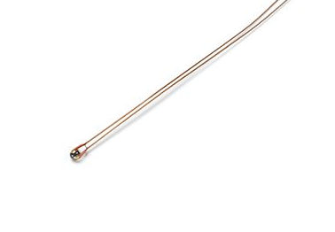
Set the temperature sensors. Both the bed and the hot-end have these glass covered thermistors, known as 'Epcos Thermistor, 100K'
#define TEMP_SENSOR_0 1#define TEMP_SENSOR_BED 1
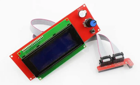
And enable the Controller board. I used the (super cheap) Ramps LCD controller board.
This has a SD card slot, but it has to be enabled in MARLIN explicitely.
/**
* SD CARD
*
* SD Card support is disabled by default. If your controller has an SD slot,
* you must uncomment the following option or it won't work.
*/#define SDSUPPORT
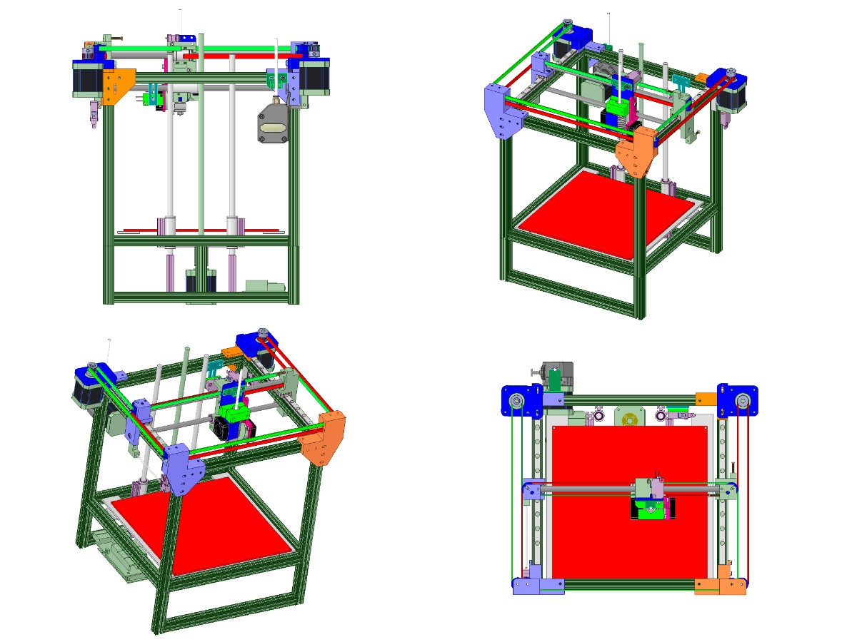
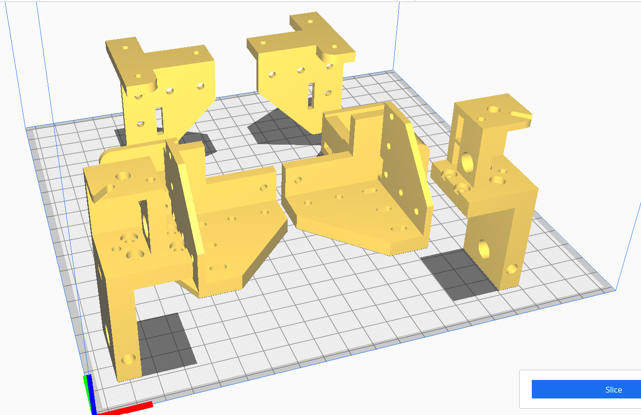
Through iteration, and modifying the drawing to match the build, I finalized the design:
For anyone who's interested: the DesignSpark file is in the 'Files' section. Later on I will produce a series of .stl files for all plastic parts, but they will probably go on PrusaPrinters or Thingiverse.
Use it however you like. But it would nice to hear from any other builders.
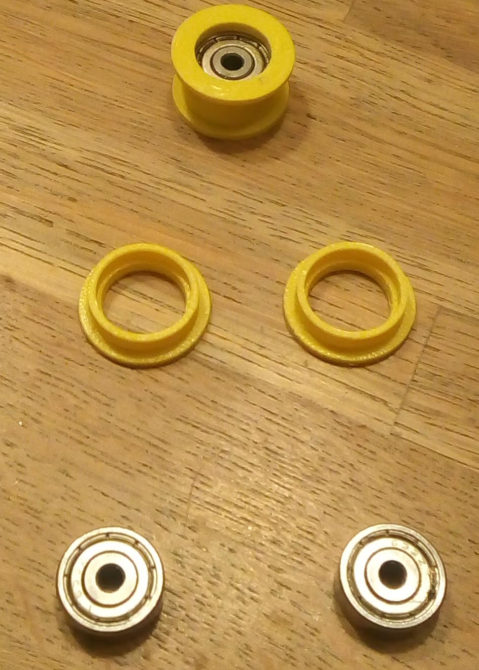
The CoreXY mechanism requires at least 8 rollers for guiding the belts. And so the set of 10 ball-bearings (set of 10 for MakerBeam) that I had seemed a good candidate for making the rollers. These bearings are 5 mm thick, have an outer diameter of 13 mm and 3 mm hole.
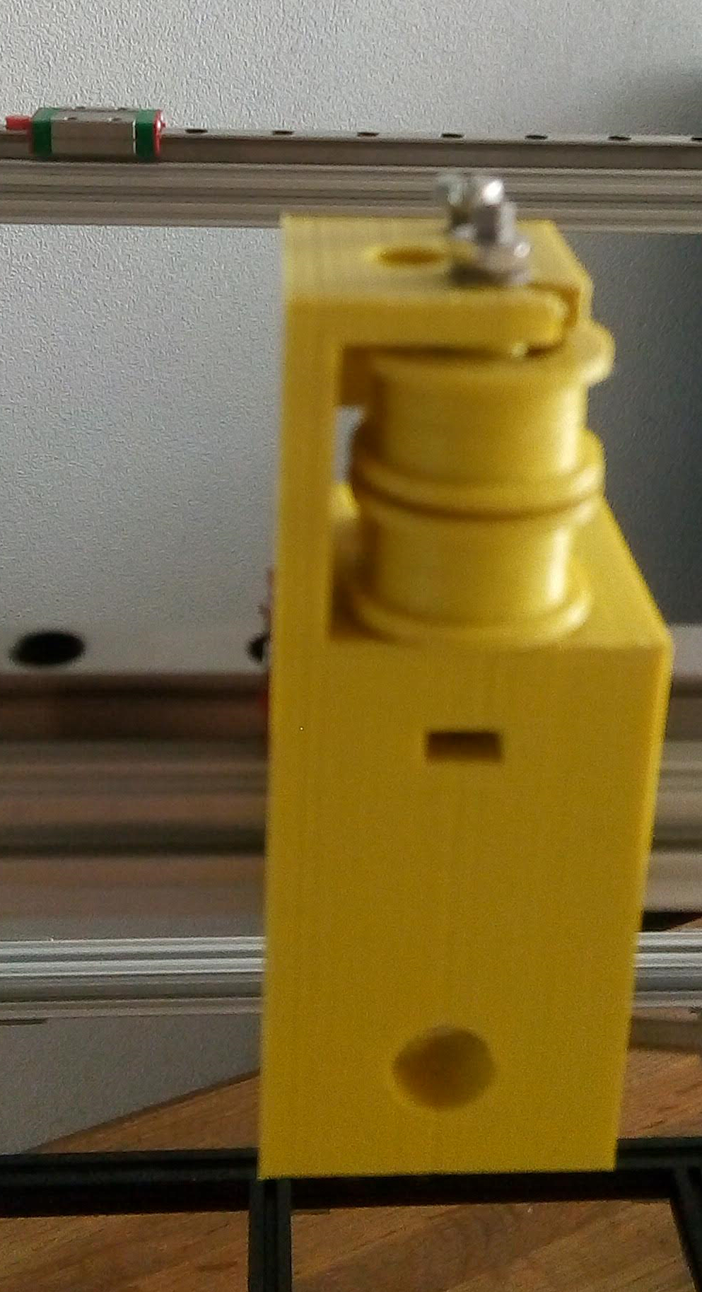
And it worked out fine. Had to fine tune the model a few times for a tight fit, but in the end rollers looked great and rolled very smooth.
After drawing the frame, and adding the pulleys in the correct position, I decided I had to draw the belts as well, just to see if my assumptions were right. And they were. It looks like this is going to fit exactly as expected.
A disadvantage of using the free edition of DesignSpark is the inability to mirror any solid object. For a printer, which needs most parts on both sides, this is inconvenient. So I created all parts on one side, exported them as .STL, and used Cura to mirror them. Afterwards it is also possible to import the mirrored parts into DesignSpark. But the imported parts are less easy to edit than the originals since they now now longer consist of basic shapes. So all rounded corners and holes are now multi-facet surfaces, which makes them cumbersome to handle.
By using our website and services, you expressly agree to the placement of our performance, functionality, and advertising cookies.
Learn More
 Cees Meijer
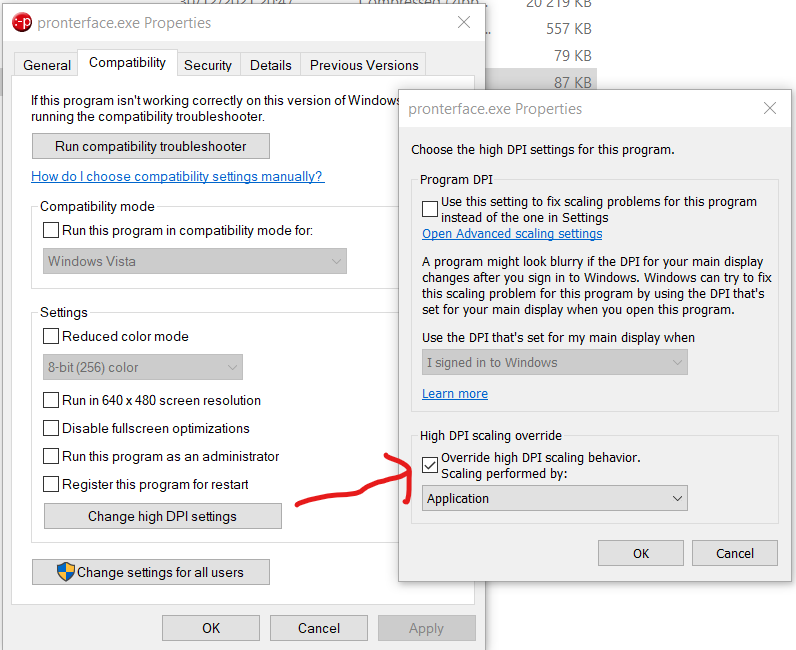

 A disadvantage of using the free edition of DesignSpark is the inability to mirror any solid object. For a printer, which needs most parts on both sides, this is inconvenient. So I created all parts on one side, exported them as .STL, and used Cura to mirror them. Afterwards it is also possible to import the mirrored parts into DesignSpark. But the imported parts are less easy to edit than the originals since they now now longer consist of basic shapes. So all rounded corners and holes are now multi-facet surfaces, which makes them cumbersome to handle.