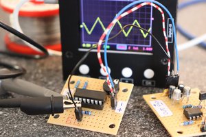
IC1 is an astable, constant period clock. The Off time is very short as required by the next stage. The period is about 20uS or about 50kHz so as to be well above the Nyquist limit of 2f of the highest frequency. I will be adding a lowpass filter to the input.
IC2 is wired as a monostable that is triggered by a Low on pin 2. The output at pin 3 goes High until the capacitor, C2, reaches the setpoint voltage on pin 5 of IC2. IC2 acts as both a sawtooth generator and comparator.
A current mirror formed by Q1 and Q2 provide a constant charging current. This causes the charging voltage on C2 to be a linear ramp.
The control voltage, CV, on pin 5 of IC2 is normally biased at 2/3 of Vcc by internal resistors. The Op Amp IC3 biases this at 1/2 of Vcc with no signal present. IC3 is wired as an inverting amplifier with a gain Av of -10 for a 5V system, or -22 for a 12V system.
With CV at 1/2 Vcc, by design the charge time is 1/2 of the clock period. So the PWM output is 50%. When the Op Amp raises CV, the charge time increases as a linear function of the change. So if it raise CV to 3/4 of Vcc, the output PWM is 75%. If CV is lowered to 1/4 of Vcc, the output PWM becomes 25%.
L1 and C4 form a lowpass filter on the output with a corner -3dB point of approximately 20kHz. I have given values for both an 8 ohm and a 4 ohm speaker.
I will be improving on this circuit. I no longer have all of my notebooks from the '70s and '80s, so I must recreate this from memory.
 Steven J Greenfield

 Lithium ION

 NNNI
NNNI
 Florian Wilhelm Dirnberger
The contest has brought in so many applications for this basic two-555 circuit. I really love the utility of it.