-
1Assembling the RAK Boards
![]()
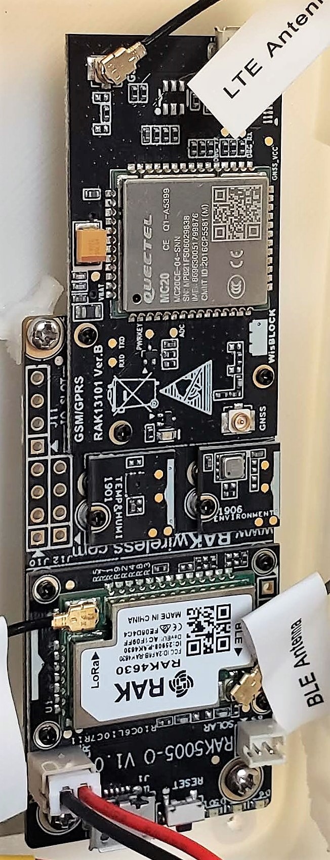
- Start with the RAK5005-O Base Board
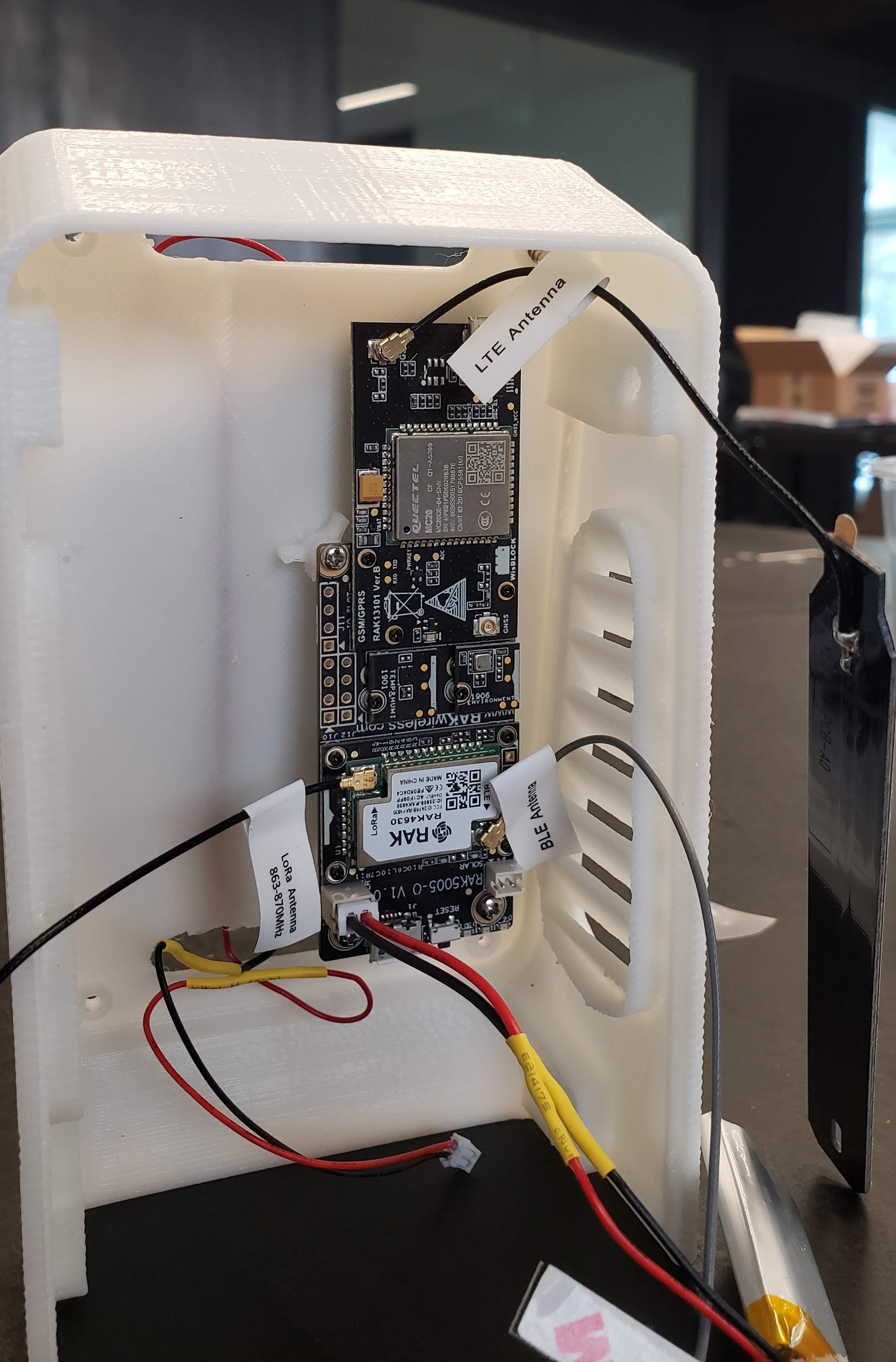
- Carefully snap in the connectors the two small Temperature and Humidity, and Environment & Air Quality modules (RAK1901 and RAK1906) as per the image
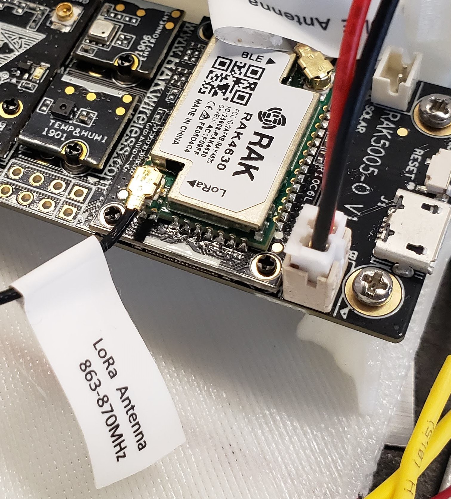
- Carefully snap in the LoRaWAN module (RAK4631) and the GSM module (RAK13101) as per the image
- Use the provided screws to fasten all the boards
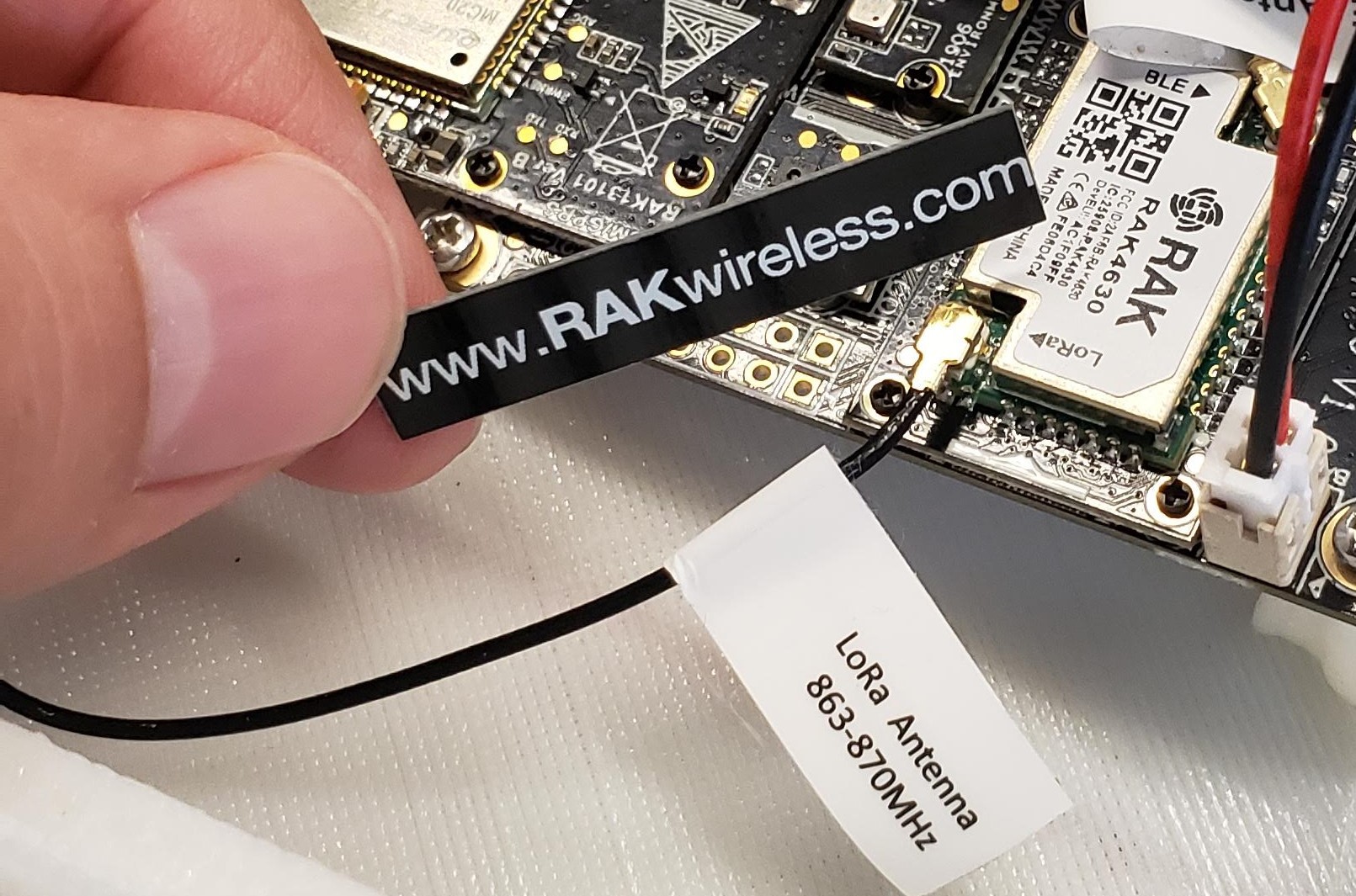
- Snap on all the provided antennas
![]()
![]()
-
2MiCS Sensor
![]()
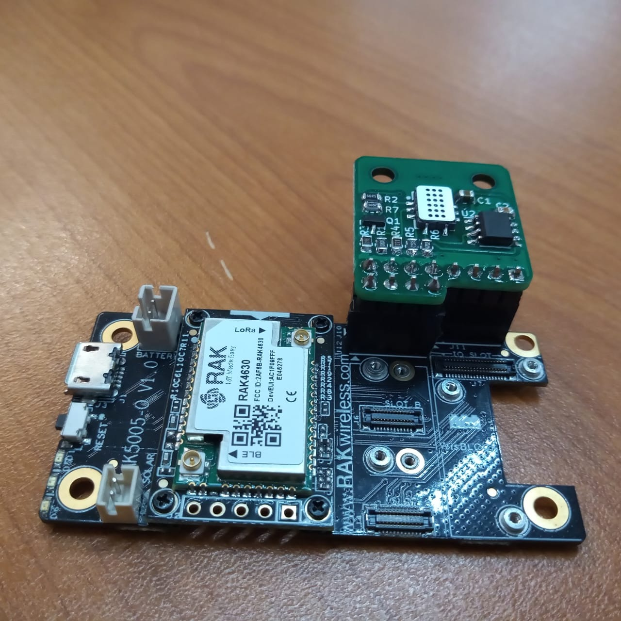
- Insert the male headers onto the RAK board as per the photo
- Solder the MiCS Sensor module to the RAK board
- Trim away any excess header material
-
3Soldering the solar cells
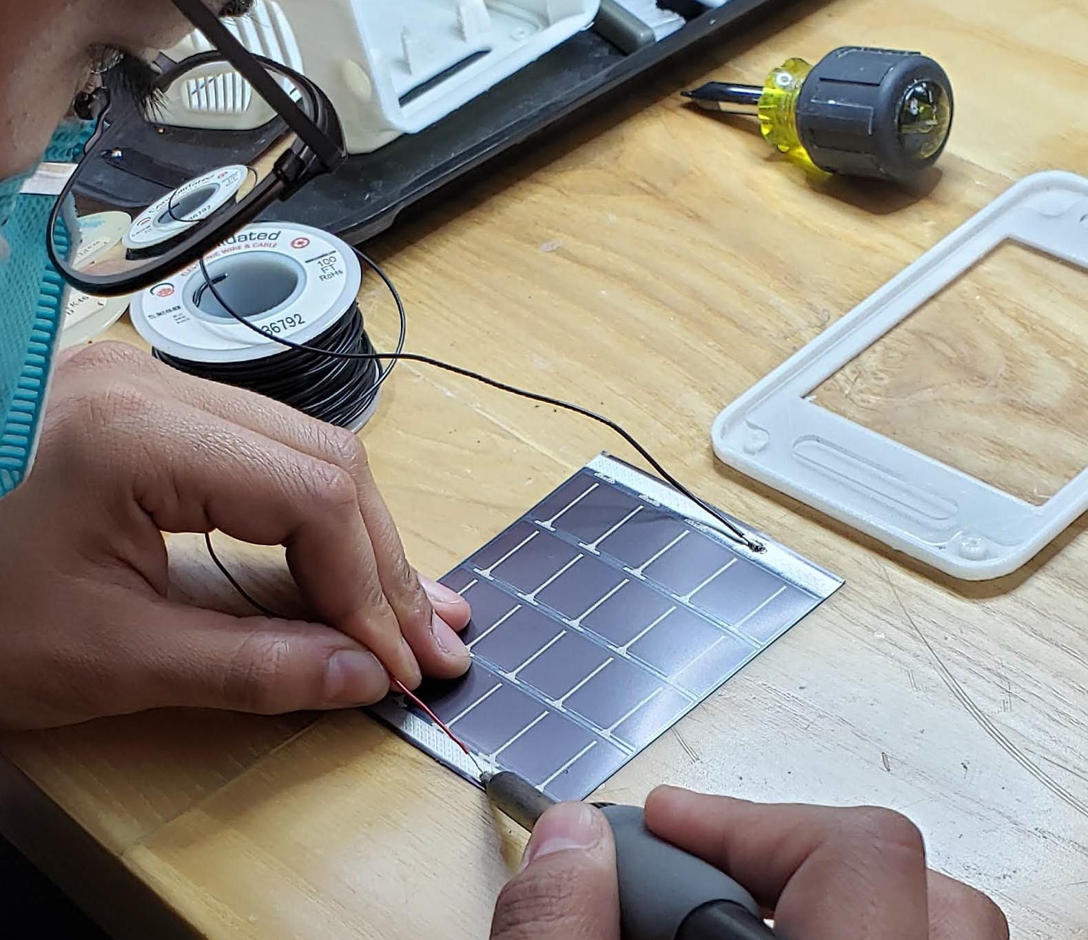
- Cut approximately 10 cm of black and red wire and strip them it on both sides
- The wires must be soldered within the "bus" area of the solar cell only (the bar across the cell)
- To the middle of the bus, scrape off a little area to remove the protective film, and add a little solder to the cleared area.
- Solder each wire to the solar cell, making sure to have the right polarity (Positive or red, is the one with the wider lines at the end, please see image)
- Splice the wires to the Solar RAK cables (here is a great guide https://learn.sparkfun.com/tutorials/working-with-wire/how-to-splice-wires)
![]()
-
4Configuring the RAK board
-
5Mounting the solar panels
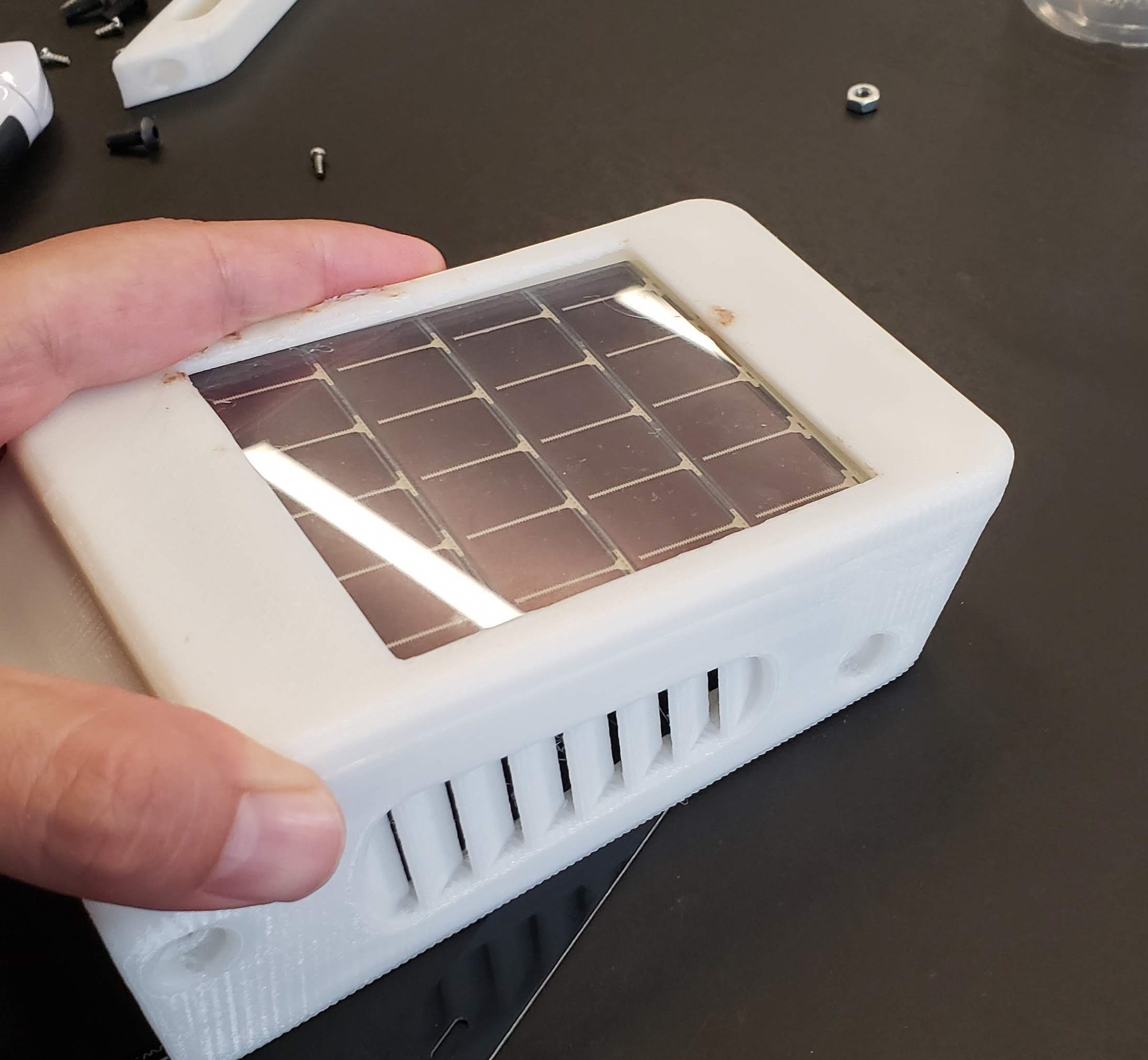
- Place the Solar Cell aligned on the Main Body
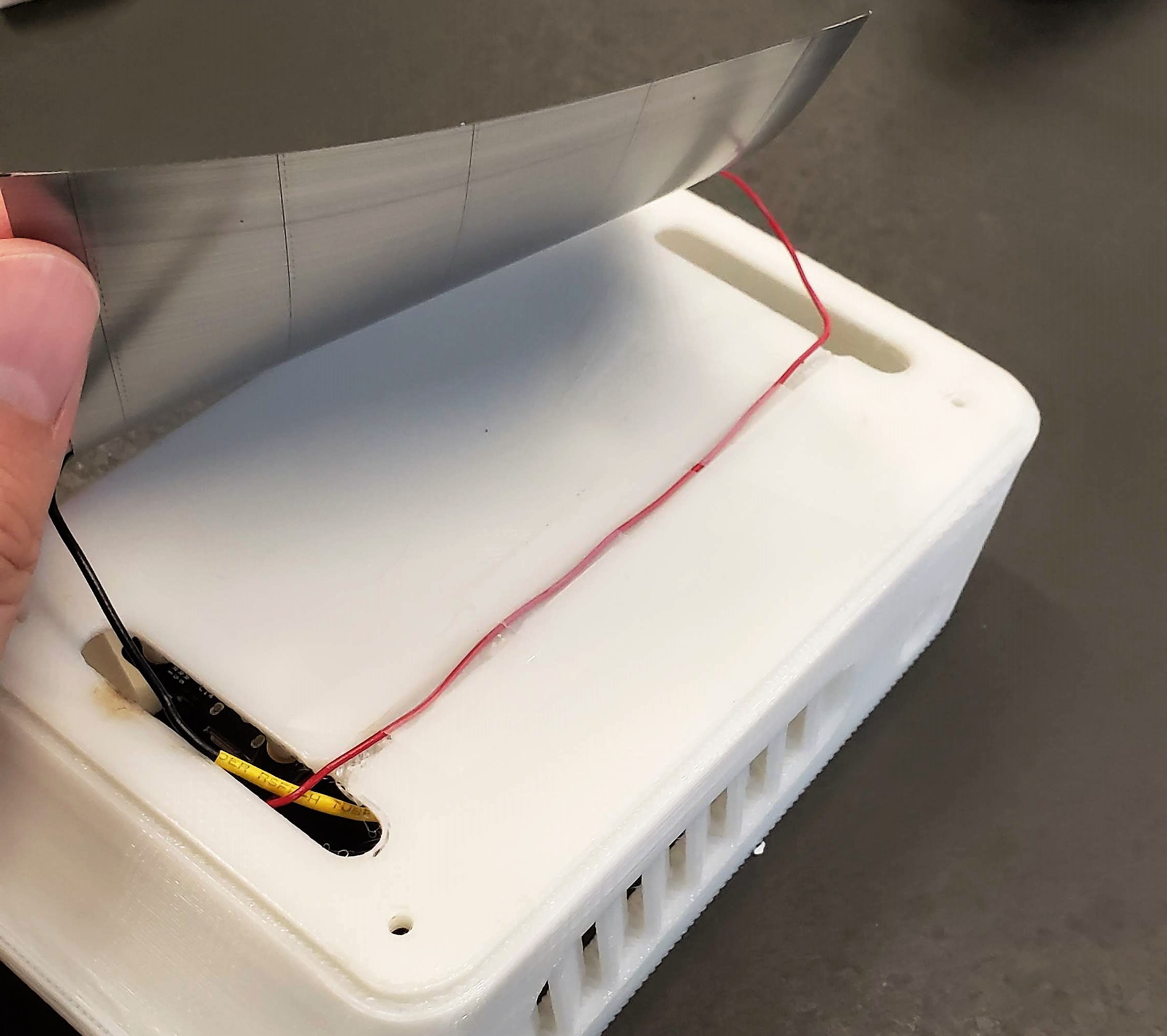
- Carefully place the Solar Panel's top wire on the top on the groove across the Main Body, adding adhesive tape to keep it in place.
![]()
- Pass the Solar Panel cables through the Main Body bottom aperture
- Place Main Body on top of the Front Cover, making sure the "up" side of the Front Cover (with the triangle shape) is facing up
![]()
- Use four thread-forming screws to fasten the Front Cover to the Main Body
![]()
-
6Helium steps
- Go to step 8 :-)
-
7Assembling the unit
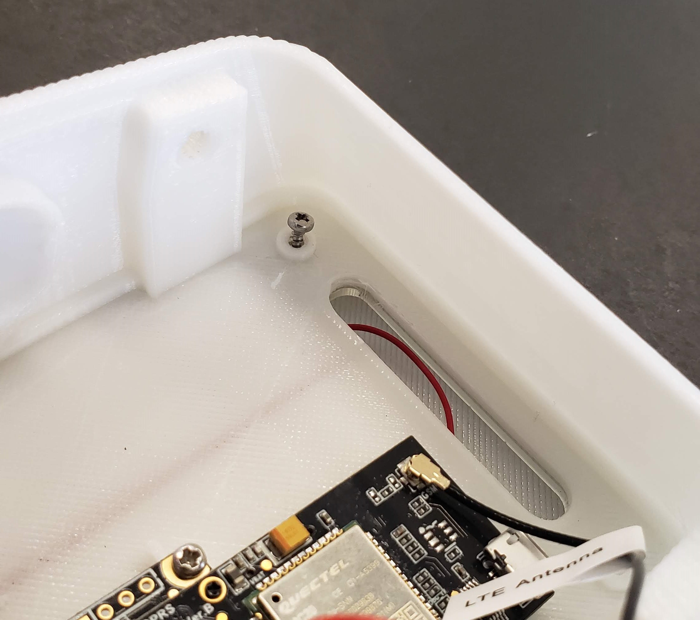
- Mount the RAK assembly and MiCS sensor board on the unit using three thread-forming screws as shown
![]()
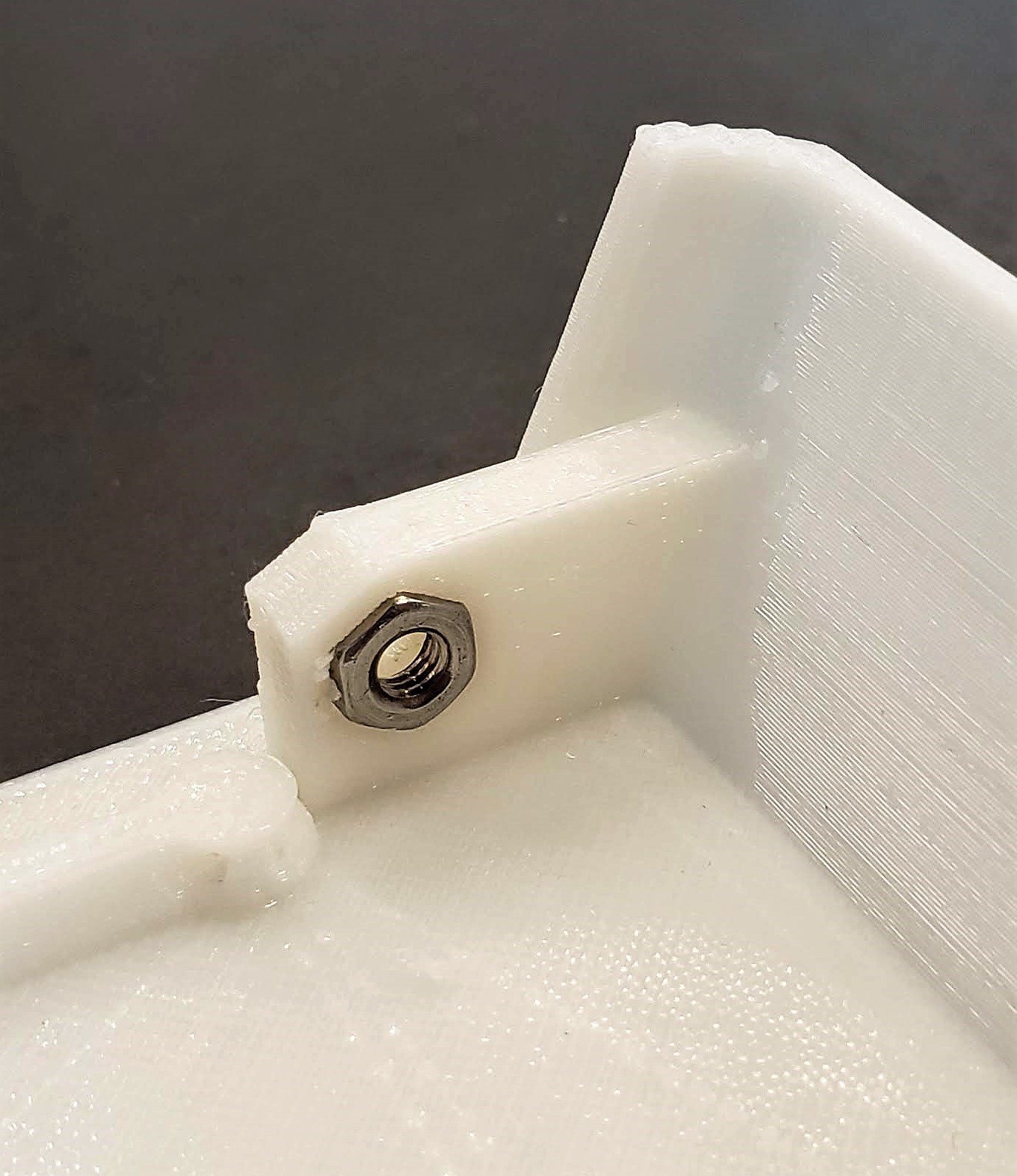
- Glue with cyanoacrylate four hex-nuts to the back cover spaces (this step is important: if the hex-nuts become loose inside, they can prevent the enclosure from opening).
![]()
Slide the Back Cover in and use the M4 screws to fasten it in place
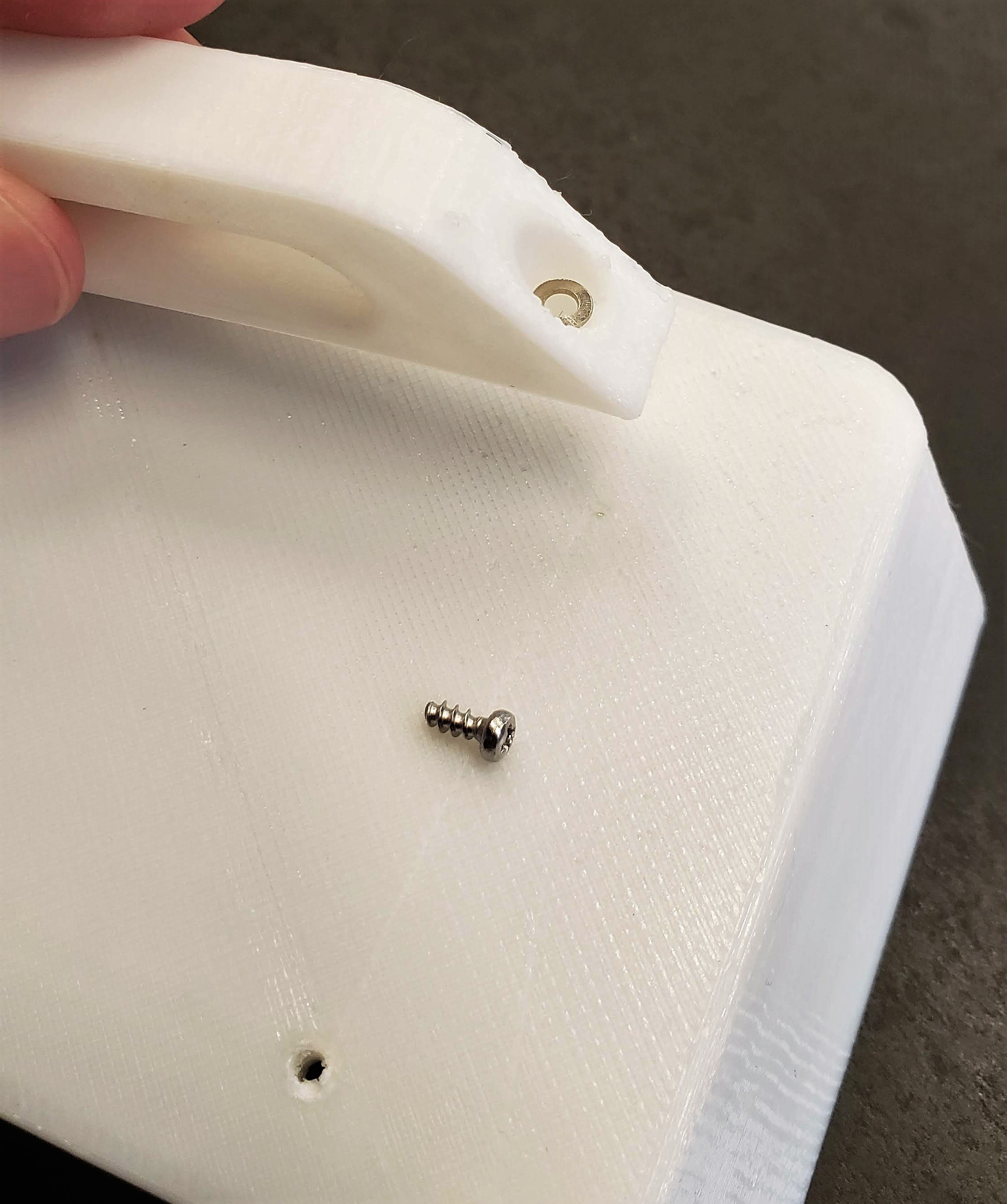
Add glue to the back of both handles and place them on the Back Cover aligned with the holes. Place a washer on each space and fasten with thread-forming screws. Important: Do not forget to glue the handles. The screws alone are not enough to support the unit.
![]()
- Mount the RAK assembly and MiCS sensor board on the unit using three thread-forming screws as shown
-
8Updating Firmware on RAK Board
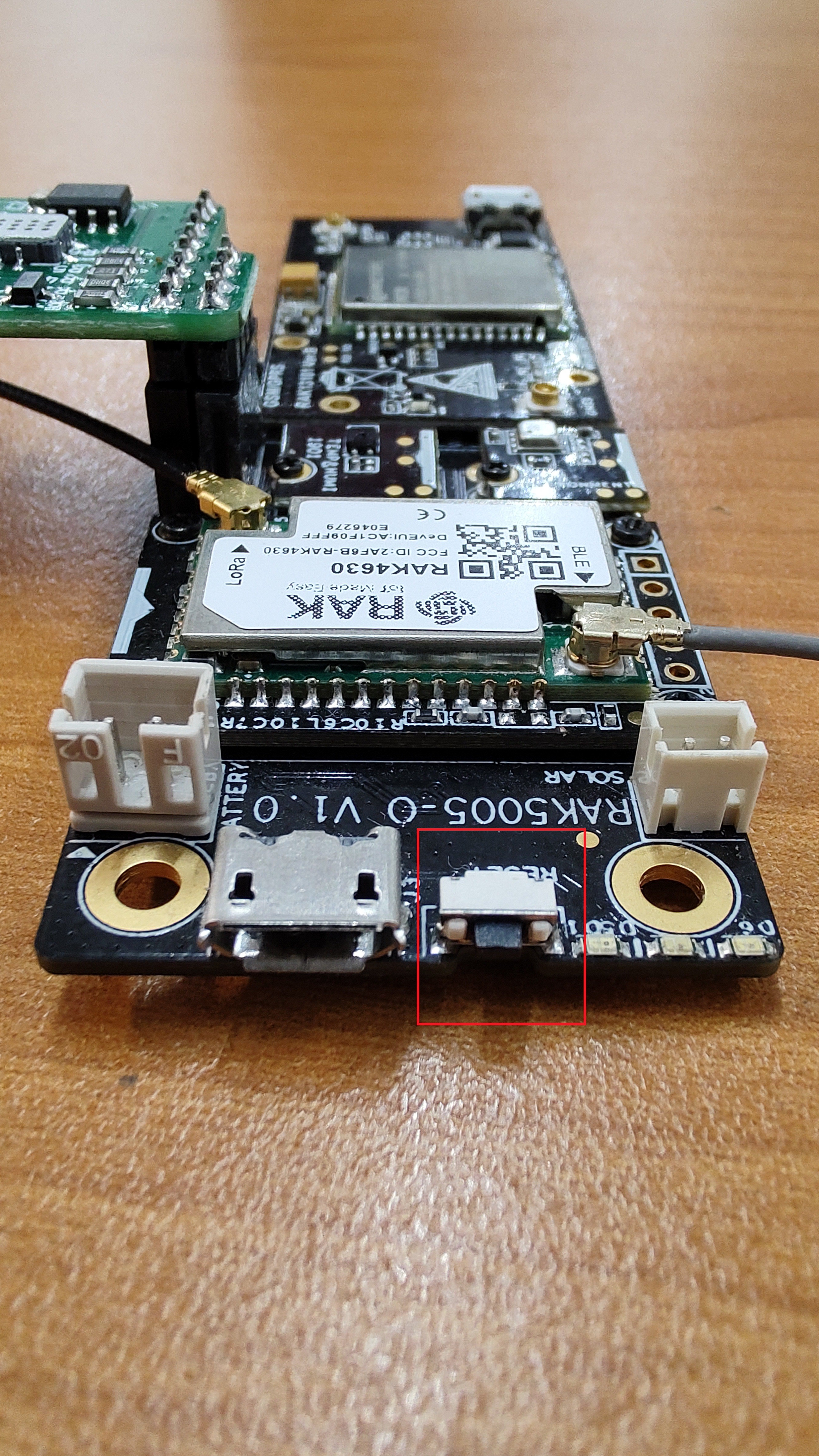
To Update the firmware inside the RAK Board its necessary to put the device in boot mode
To do so, you just need to push twice the reset button on your board
![]()
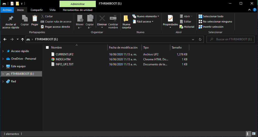
If you have activated the boot mode you will see a new device which will look like a mass storage device, this is bootloader accept a file with sufix .UF2
![]()
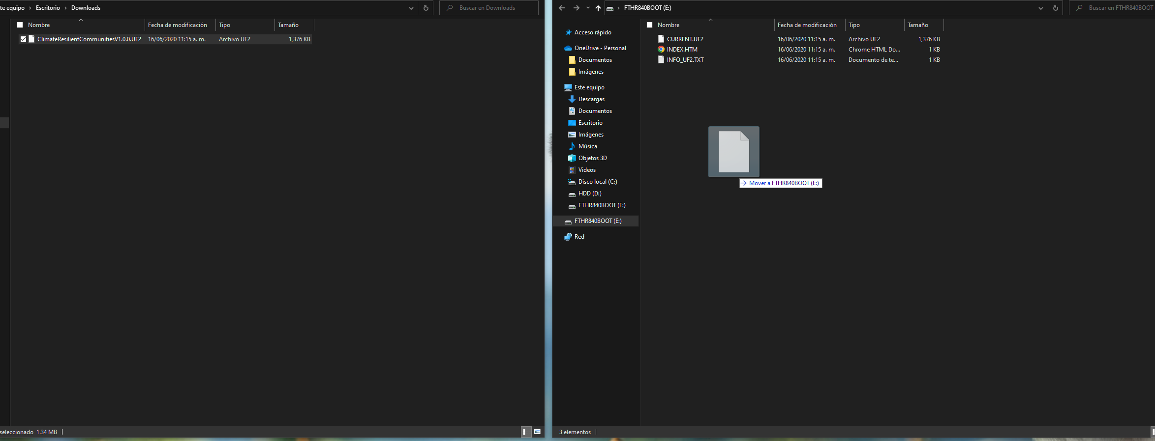
Now for updating your device you only need to drag and drop the ClimateResilientCommunitiesV1.0.0.UF2 file which can be downloaded from here
![]()
When the copy has finished the device will resets in automatic and it will be ready to be configured.
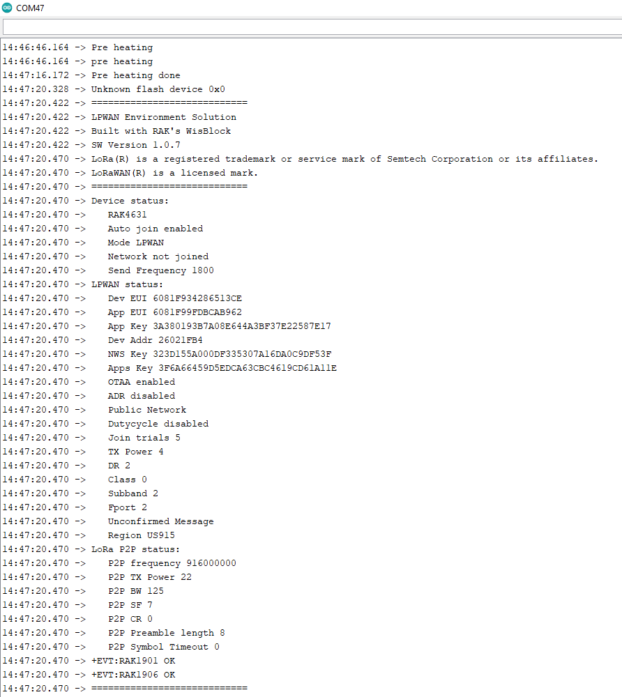
You can check if the device was well update opening the serial port on any terminal, in this case i will use the embedded on Arduino IDE.
You should see this messages on the terminal.
![]()
Its important to be aware that the device will Pre-Heat the NO2 sensor for 30 seconds so you need to wait 30 until you see the next messages
-
9Configure Helium Console to connect our device
Now we have programmed the device, but in order to configure it we first need to know the keys we're gonna be ussing to acces to the Helium Network, which is based on LoRaWAN.
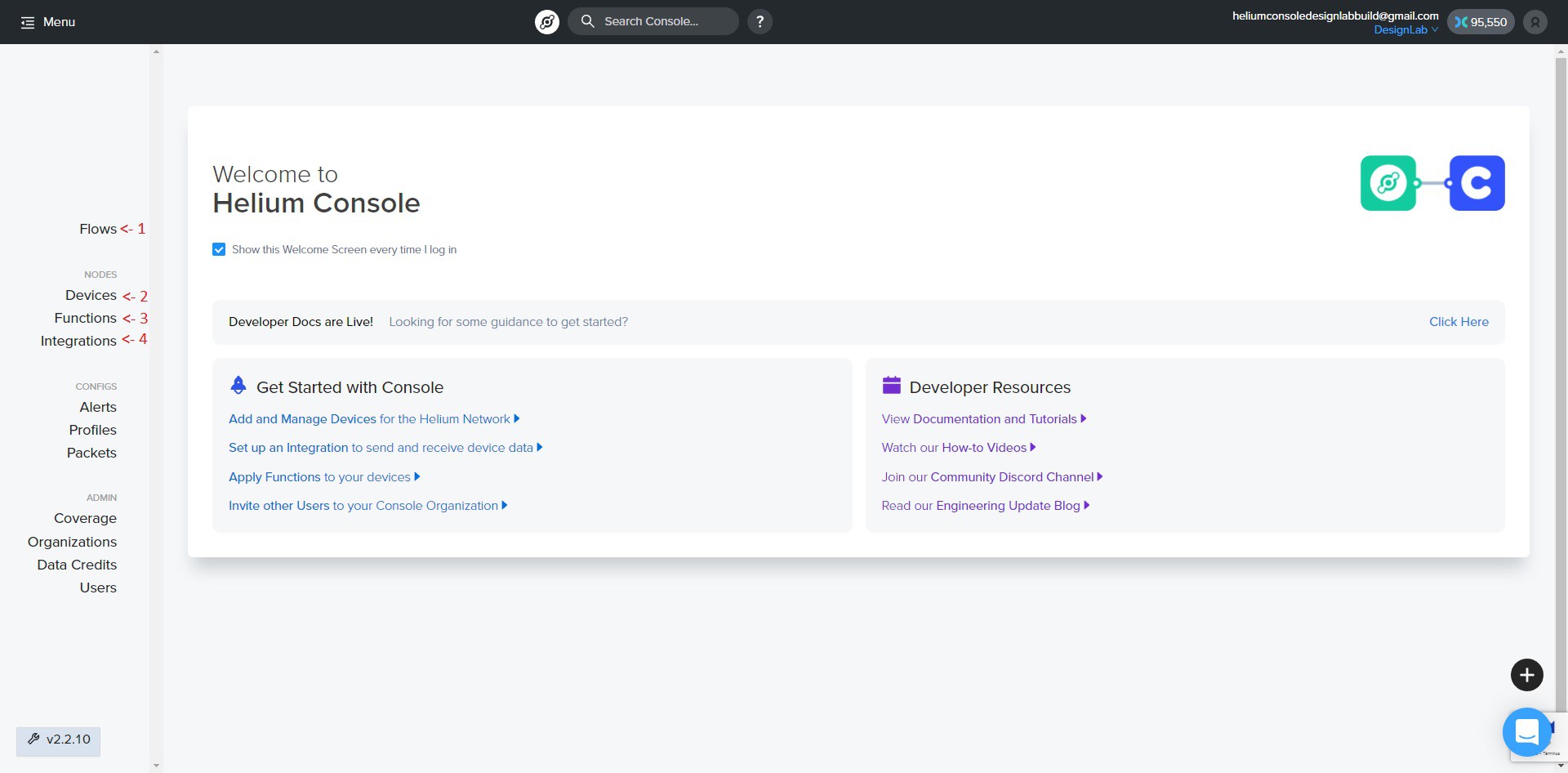
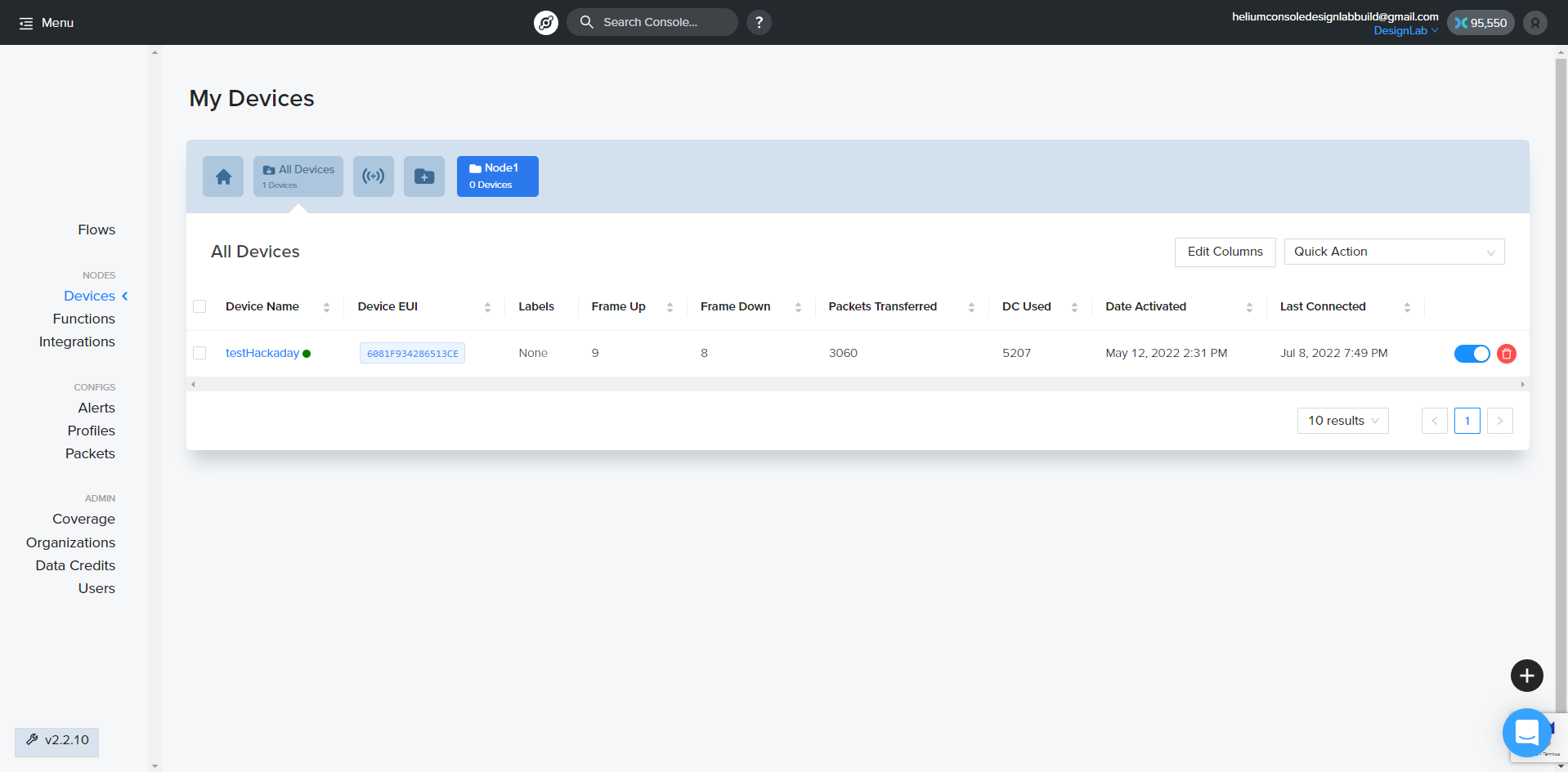
Once you have logged in into the Helium console you'll see somenthing like this. Lets review each part that we will be using of the platform.
![]()
- Flows: This section allows you to connect between Deivces, Functions and integrations.
- Devices: This section let you create and monitor sensors, nodes, devices or whoever you call the end device.
- Functions: This section allows you to create a decoder for the payload your Device is sending, so it can be parsed as a JSON.
- Integration: This section let you create connections to different ENDPOINTS, which can be easily identified as web severs, applciations, etc.
What we're focusing in this part of the project is in creating a device so click on the number 2 aka Devices.
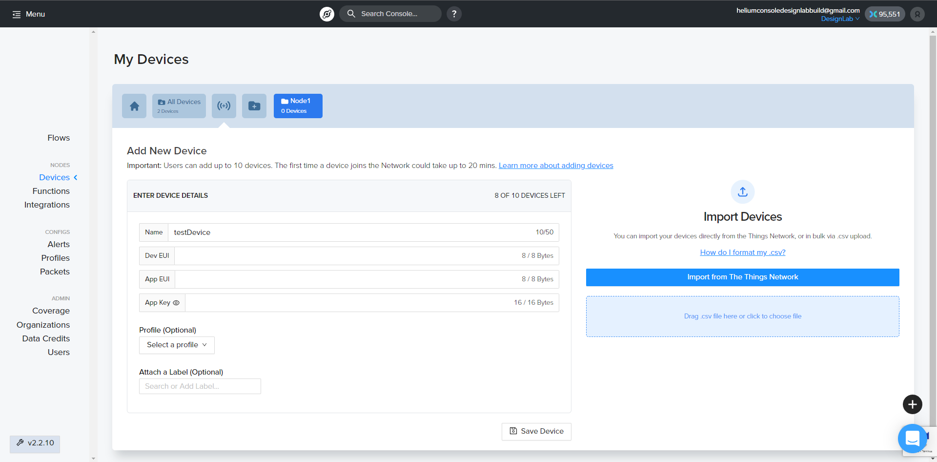
Click on the marked button "Add New Device"
In this screenshot you can see that i have already created one.
Now you can add the Device name (An easy identifier for you) and also the device credentials, you can leave the ones that Helium gived to you or create your own.
Additionally you can attach a label so you can organize your different sensors by labels, in this case its not mandatory.
Once you have added the device you will need to wait up to 20 min to be able to start sending data cause it is being added to the
For configuring the WisBlock device you need to save your DevEUI, AppEUI, and AppKey
-
10Configure your Device with your credentials by UART
Things must be configured:
- Band (US915 or EU868)
- Sub-Band (Usually is used sub-band 2 for US915 if not this region this can be skipped)
- Packet transmited frequency: 3600 (each hour)
- Transmit power Set OTAA as the LoRaWAN autenthication method
Configure by serial port
The device can be configured by the serial port using simple AT commands, you can find all the commands available HERE.
First of all you need to restart your device and open a serial terminal, in this case ill be using the arduino's one
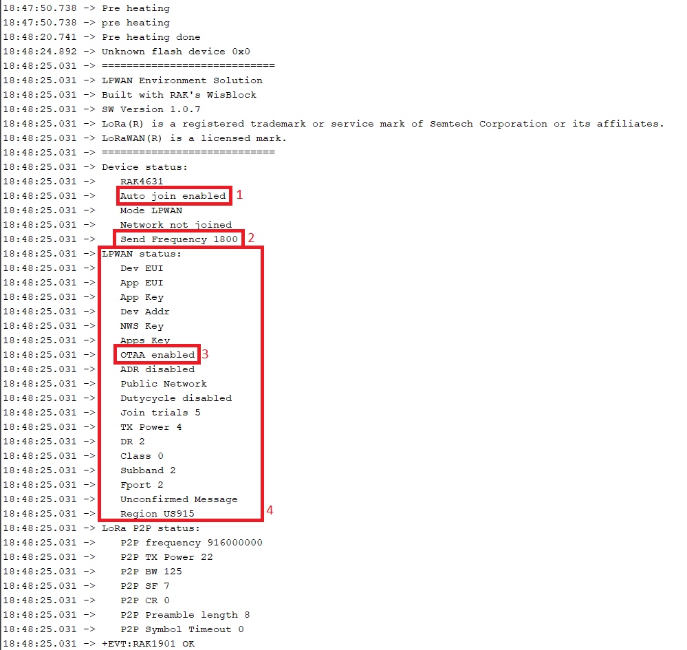
You should see the device status once the pre-heating has finished.
![]()
- This field will let us know if the device will try to join the network automaticaly once is on
- This field will let us know the time between each transmition in secons
- This field will let us know what kind of authentication are we, using in this case OTAA
- This fields will let us know all the LoRaWAN information as the Class, in thi cas Class A, the sub-band, the region, if the message is confirmed etc.
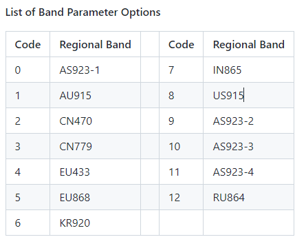
Configure the band depending on the region you are:
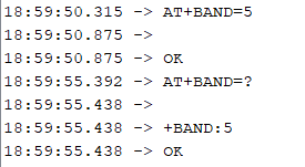
You can always verify the band that you're on working with the command "?" after all the equal signs.
AT+BAND=?
The number thats shown can be linked to a region by the next table
In order to change it to for example EU868 we need to use the next command
AT+BAND=5
Now lets configure the authentication as OTAA:
Configure OTAA
AT+NJM=1
Configure automatic Join
AT+JOIN=1:1:7:10Configure your credentials
To configure the credentials is necessay to use the next commands, MAKE SHURE YOU CHANGE THE "XXXXX"s FOR YOUR HELIUM CREDENTIALS CREATED THE STEP BEFORE.Hint: you can use the webpage https://loratools.nl/#/ to get a little help with the copy/paste of the keys.
DevEUI
AT+DEVEUI=XXXXXXXXXXXXXXXX
AppEUI
AT+APPPEUI=XXXXXXXXXXXXXXXX
AppKey
AT+APPKEY=XXXXXXXXXXXXXXXXXXXXXXXXXXXXXXXX
Configure the report time
To configure the time interval you need to calculate it with seconds.
AT+SENDFREQ=3600
REMARK 1 After changing LoRaWAN® parameters or LoRa P2P settings, the device must be reset by either the ATZ command or pushing the reset button.
REMARK 2 The Serial port connection is lost after the ATZ command or pushing the reset button. The connection must be re-established on the connected computer before log output can be seen or AT commands can be entered again.
REMARK 3 The Serial port is setup for 115200 baud, 8N1. It cannot be changed by AT commands.
2022 HDP 4 - Climate Resilient Communities
Air quality sensor systems for urban bodies of water, so that the population can avoid potentially dangerous exposure
 Supplyframe DesignLab



Discussions
Become a Hackaday.io Member
Create an account to leave a comment. Already have an account? Log In.