Michael Gardi
-
Rejoice the Keyboard Has Arrived
10/28/2022 at 22:32 • 0 commentsI've kind of been in a holding pattern waiting for the keyboard "kit" to arrive but no more as it was delivered this week. This is a classic retro-style ASCII keyboard, modeled after the ADM-3A keyboard, which can also be populated to fit perfectly in an Apple II/II+, or an Ohio Scientific Inc. computer, or as it turns out an MCM/70. For details check out the Unified Retro Keyboard project.
I was able to purchase the keyboard PCB, a set of Futaba MD-4PCS keys, a stabilizer panel for the Futaba keys, and a keyboard encoder card from Dave from osiweb.org.
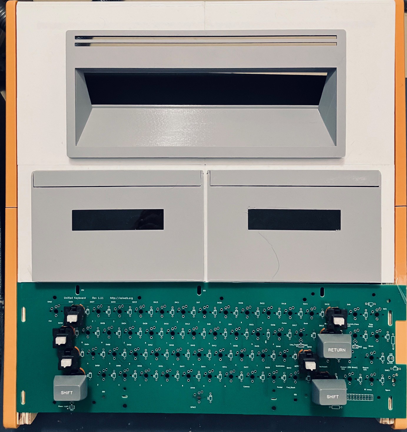
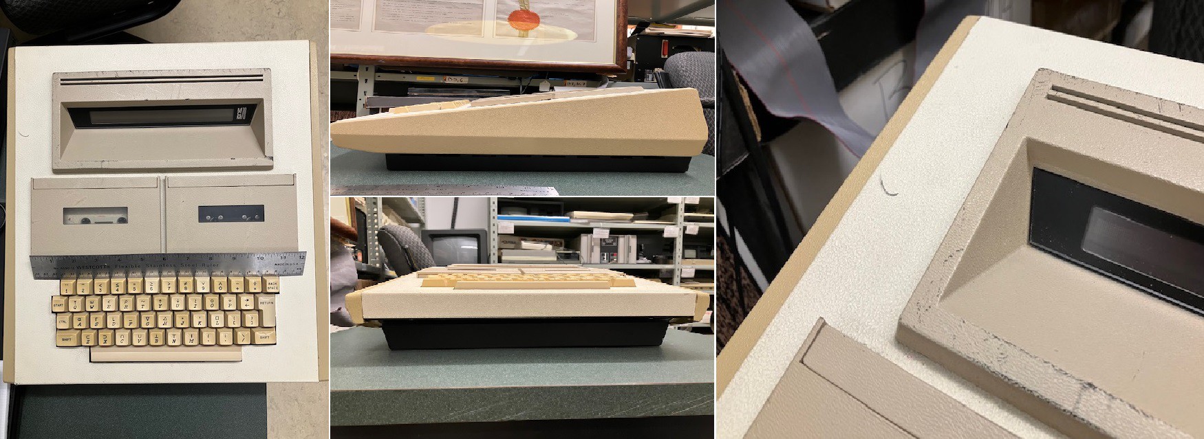
The first thing I did was to set the keyboard PCB with a few keys loosely set in place onto the partially finished MCM/70 case to get a rough feel for what it would take to integrate the keyboard.
![]()
I was happy to see that while it looks like a tight fit, I am sure that I can make it work. So with some confidence I went ahead and assembled the encoder and keyboard. I'm not going to detail the process here since it was mostly identical to the work I did on my Sol-20 Reproduction. For details check out:
- The Keyboard Encoder
- Keyboard Construction (Note that the newer keyboard PCB has the discrete diodes and resistors pre-populated on the board. A real time saver. Thanks Dave.)
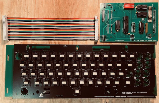
Here they are.
![]()
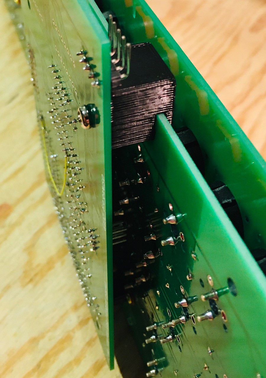
By design the encoder can be mounted onto the back of the keyboard via the 40-pin headers. This is what it looked like for the Sol-20.
![]()
However there is not enough room in the MCM/70 case, so I am going to use the ribbon cable pictured above.
Next testing.
-
Hoping for Some Legendary Keycaps
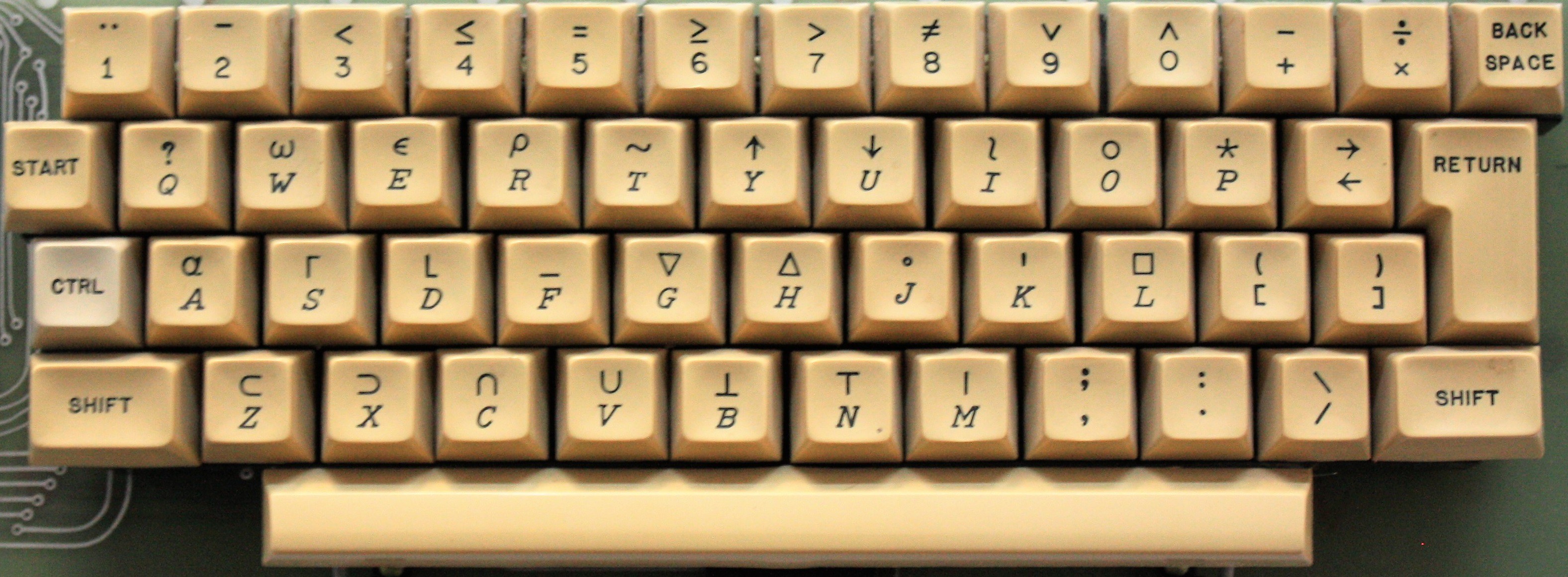
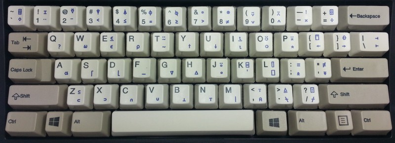
09/07/2022 at 15:38 • 3 commentsTo say that the MCM/70 keyboard is unique would be an understatement. Because it supports APL out-of-the-box there are twenty plus keys that have special shifted characters like α and ∆. Not to mention that the more standard special character keys are in different places than on a modern keyboard. Plus I don't know if I've ever seen italicized letter key legends .
![]()
Believe it or not you can still purchase APL keycaps, like this set from UNICOMP (for a pretty reasonable $35).
![]()
While there appears to be a standard APL layout for the keys, the key legends look quite different. So I'm resigned to having to make my own keycaps. But how?
After doing a bit of research I thought there were four potential options:
- Waterslide Decals. Key legends are printed on special waterslide paper and transferred by first soaking them in water then sliding the clear top layer with the glyph and some adhesive to the keycap.
- Dye Sublimation. Key legends are printed (reversed) with special dye sublimation ink. The glyphs are then positioned directly on the keycap and transferred by applying heat (400 F - can be accomplished with a hair curler) and pressure.
- Laser Etching. While directly etching the legends onto a keycap has not worked very well, DIYers have had success by coating the keycap surface with print toner or dye sublimation ink then using laser etching to fuse the glyphs to the surface. Once done the excess toner or ink is washed away.
- Purchase. A number of vendors will now allow you to submit SVG files with your keycap legends and produce the keys for you.
These are arranged for the most part in easiest/cheapest to hardest/most expensive order. So my plan is to start at 1. and keep trying these methods in order until I get a result that I'm happy with.
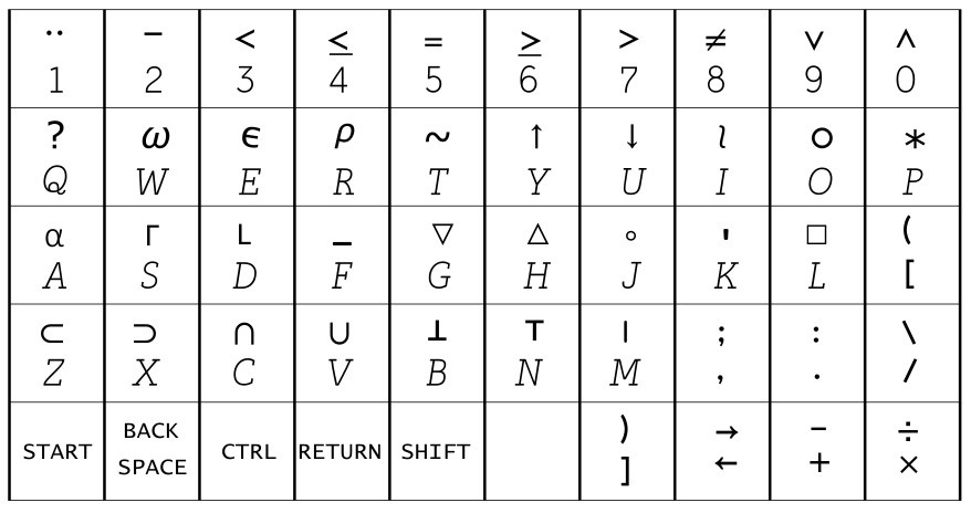
Regardless of the method that I use, I need to have the key legends defined. To that end I have used Inkscape to create SVG versions of the legends that can be scaled to fit the keycaps. Here is what they look like.
![]()
Still needs a bit of work but a pretty good start.
-
Quick Update
07/12/2022 at 16:29 • 0 commentsI haven't posted for a while because I'm still waiting on the keyboard PCBs from Dave, which had to be manufactured since he was out of stock. I'm still researching how to make the proper keycaps but I am reluctant to commit to a technique in the absence of the actual hardware. Stay tuned.
-
Top Panel
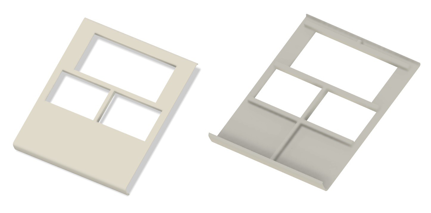
06/02/2022 at 14:30 • 0 commentsWith the frame built it's time to add the top panel. First I modeled the panel in Fusion 360. Notice that I don't have a cutout for the keyboard yet because I don't have the keyboard yet.
![]()
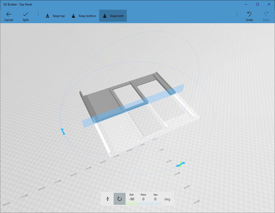
I have added integrated support "beams" to the underside. Since this model is way to big for my print bed I used 3D Builder (which I believe ships with all current Windows versions) to cut the model into six pieces. The Split tool in 3D builder is easy to use and works great.
![]()
I did all of the splits down the centerline of the vertical and two center horizontal beams so that I would have a lot of surface area when gluing the pieces back together.
![]()
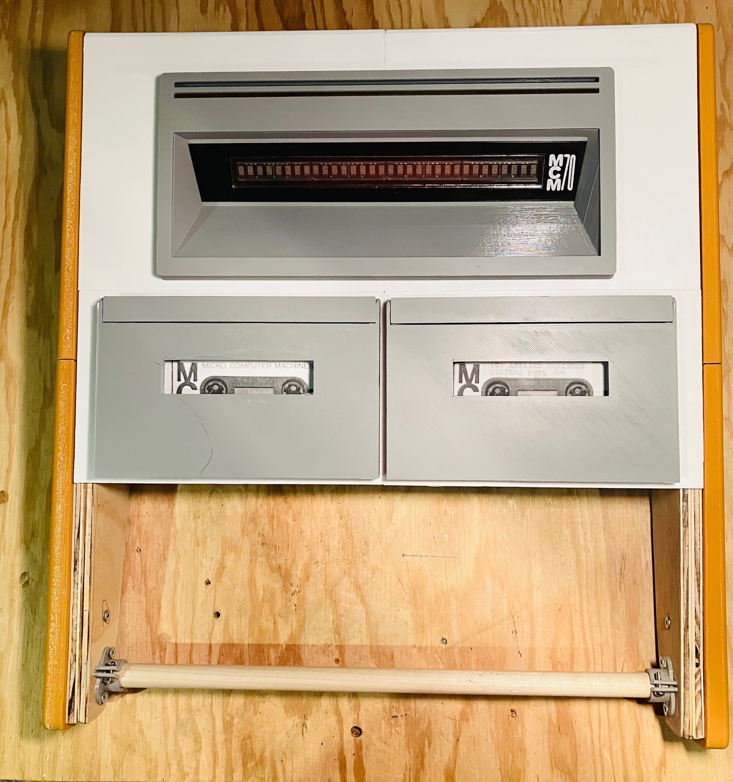
So far I have printed and assembled the top four panel parts. I used a gel CA glue to attach the pieces together. I printed the top panel in white because I could not find a suitable pale yellow filament. I have seen images where the panel appears to be white but that could just be due to the lighting when the photo was taken. I'm not opposed to painting the top panel at some point closer to the end of the project.
![]()
And this is what it looks like so far with the display and cassette drives installed.
-
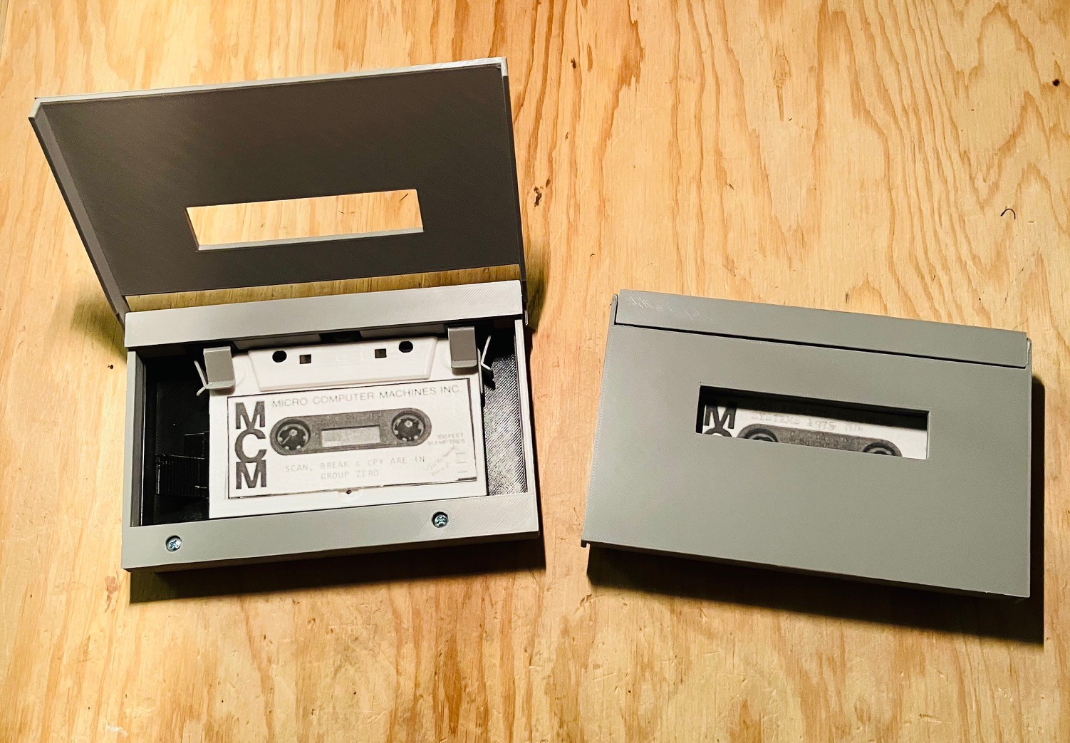
Placebo Cassette Decks
05/31/2022 at 06:35 • 0 commentsSo I'm adding fake cassette decks to my MCM/70 reproduction and you might be wondering why. Couple of reasons.
First of all the YUCoM software that I am using emulates a machine that has two cassette decks. When I visited the the York University Computer Museum Zbigniew Stachniak (Ziggy) mentioned that MCM did ship a model with no cassette decks (and one with a cassette deck and a modem), but that without cassettes the machine was basically just an APL calculator. So I could have saved some time and still been historically accurate I guess.
More importantly though, virtually all of the online images of the MCM/70 feature the two tape deck model. It's important to me that my reproduction is clearly recognizable as an MCM/70 so placebo cassette decks it is.
Here is the result of my efforts.
![]()
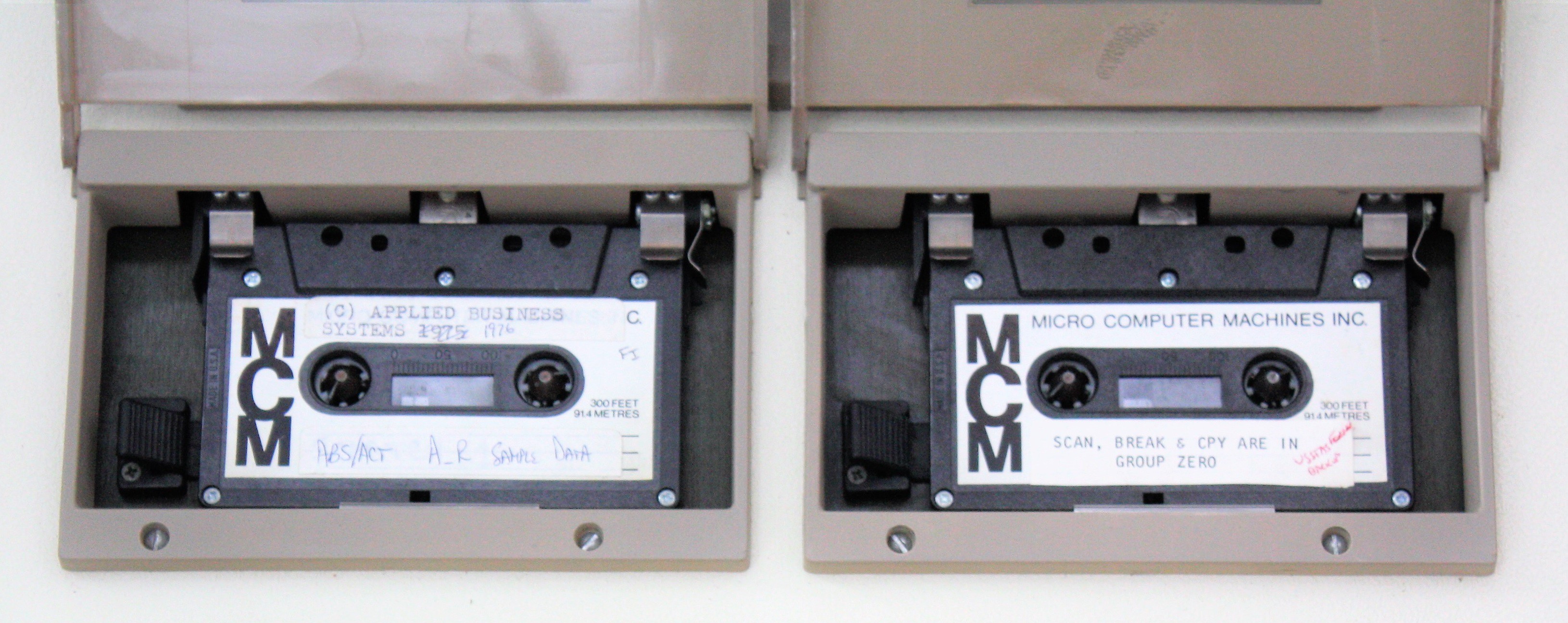
Based primarily on this photo and the measurements that I took at the museum.
![]()
I even got the tape eject lever working ;-) I still have to laser cut the acrylic windows for the lids.
-
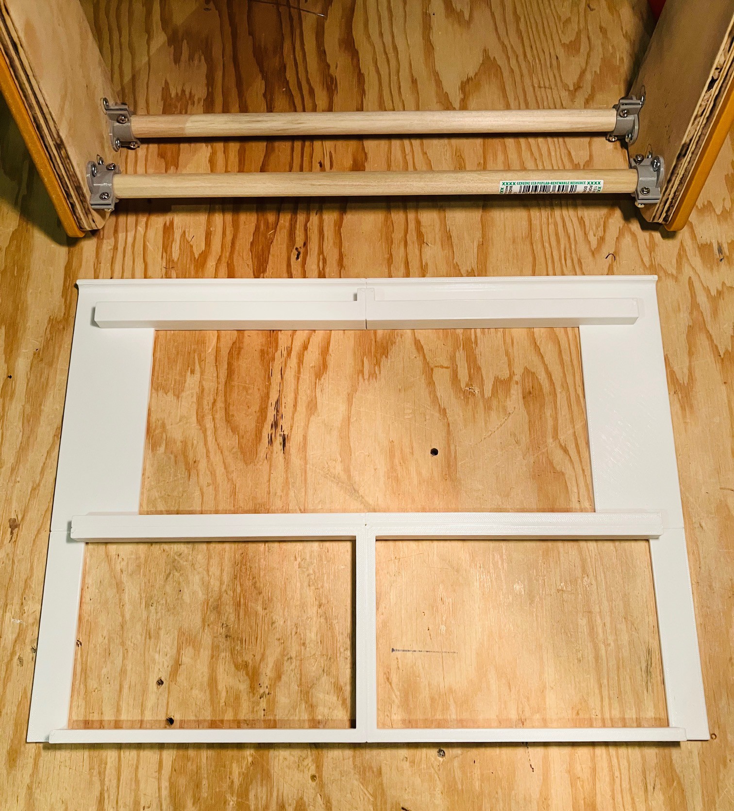
The Frame
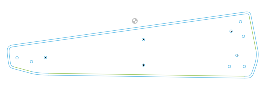
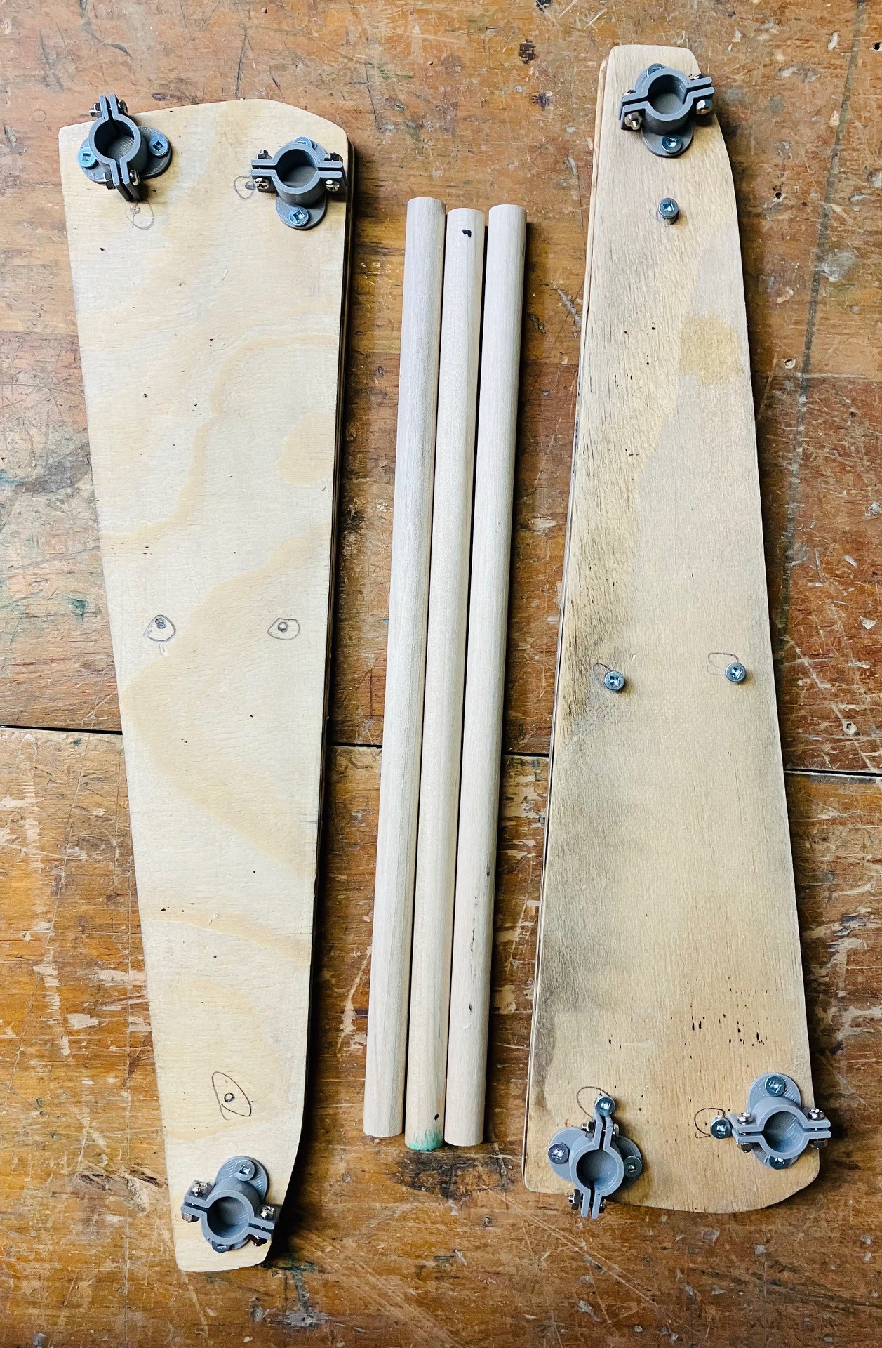
05/27/2022 at 01:30 • 0 commentsI created a template to cut out the "in"side panel pieces for the MCM/70
![]()
frame. The outside line represents the side panels as printed, while the inside outline is 3 mm smaller and is used to make an inner frame to support the top panels. Holes indicate positions where screws (#6 x 3/4 inch) will be used to attach the printed side panels to the inner frame (black dots), and attach flanges for 1/2 inch doweling to the inside frame (#6 x 1/2inch screws). I laser cut the template from a scrap of acrylic I had lying around to use as a positioning guide for the screw holes.
![]()
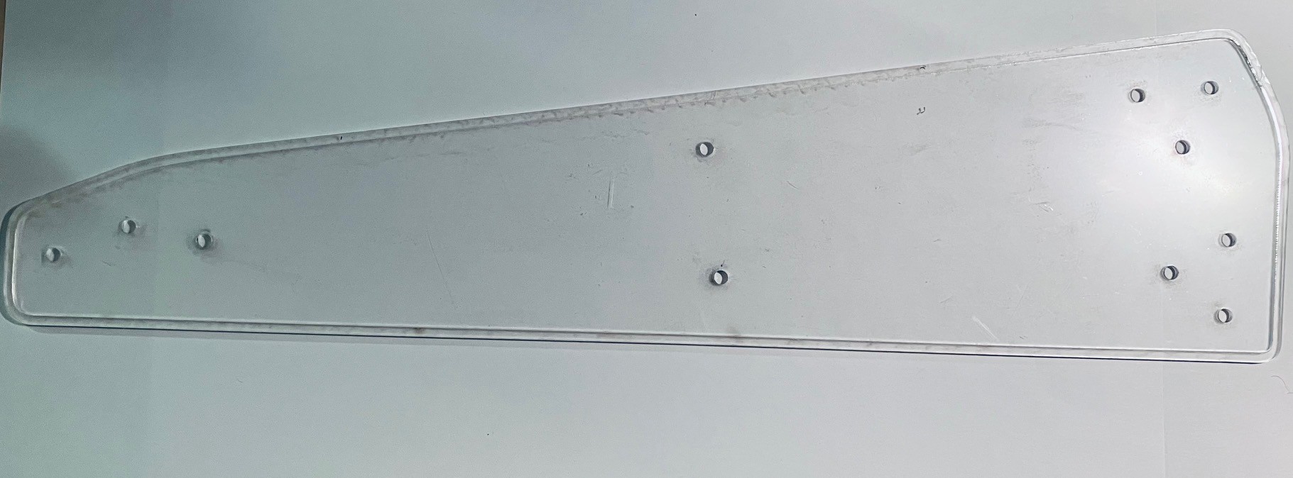
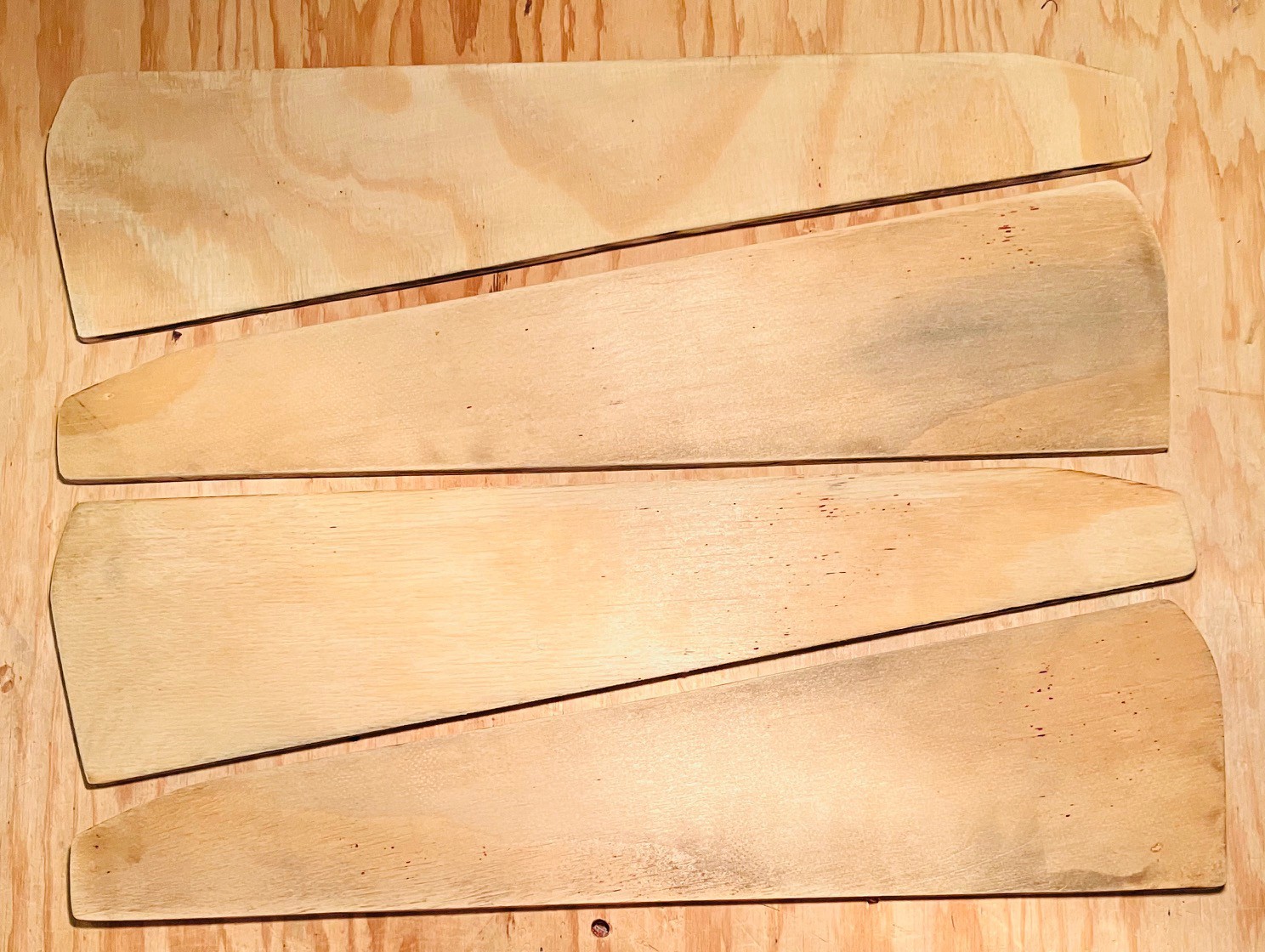
Then I laser cut four of the smaller pieces from 6 mm plywood.
![]()
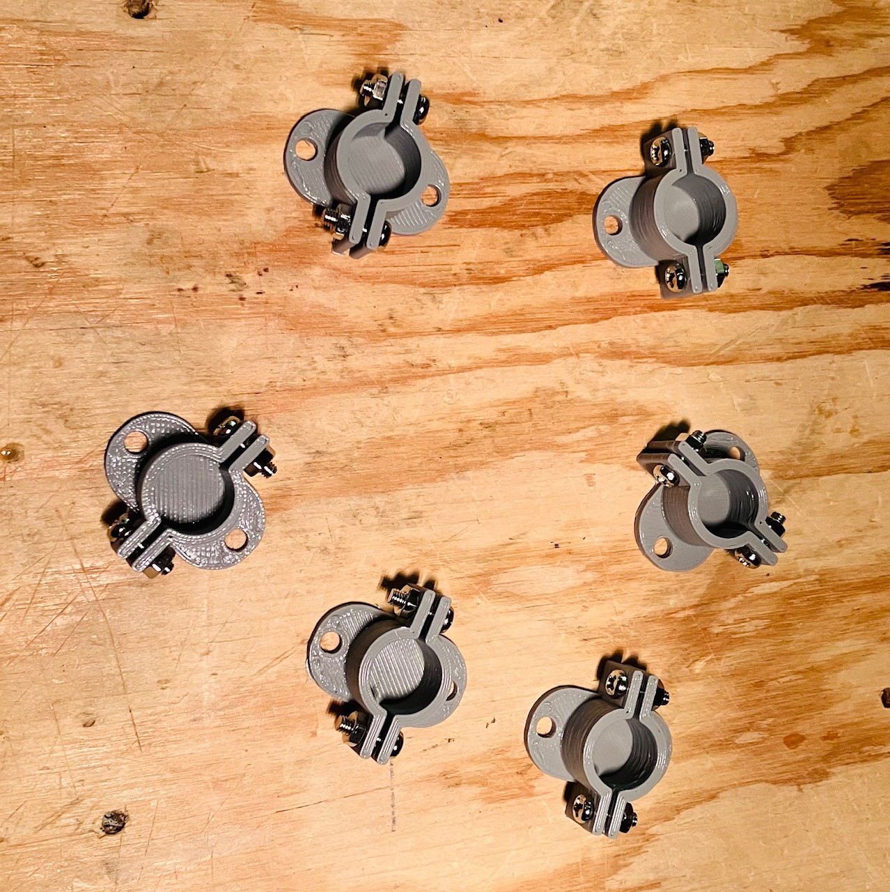
I designed and printed six flanges to anchor 1/2 inch dowels.
![]()
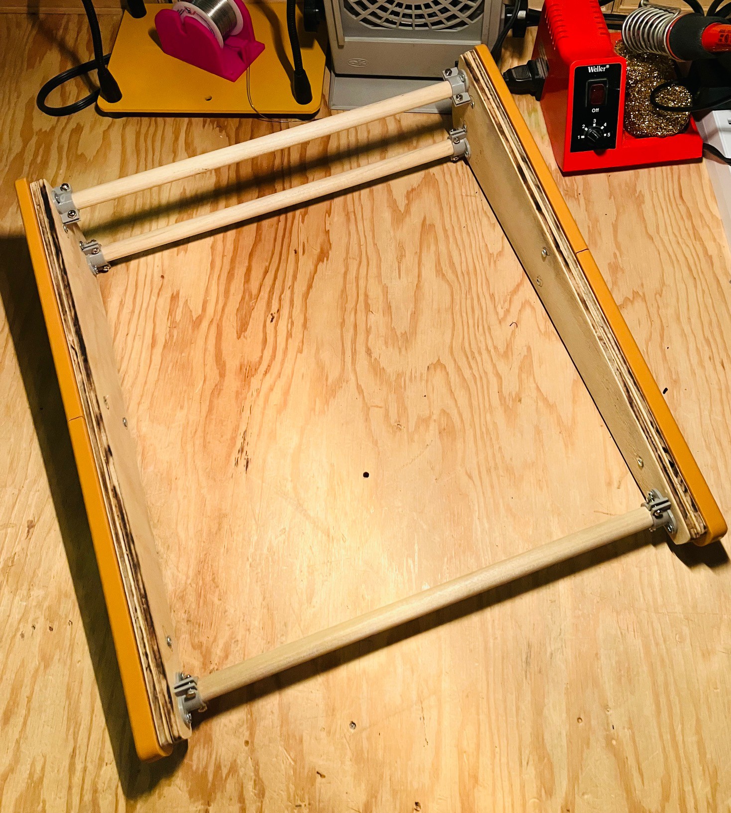
Then I glued two panels together for each inside frame and mounted the flanges based on the template.
![]()
The dowels were cut so that the width of the machine from the outside edges of the inner frames is exactly 13.25 inches just as it is in the original. I attached the printed side panels to the inner frame pieces and inserted the dowels.
![]()
So I now have a solid frame to which I will mount the rest of the MCM/70 components.
-
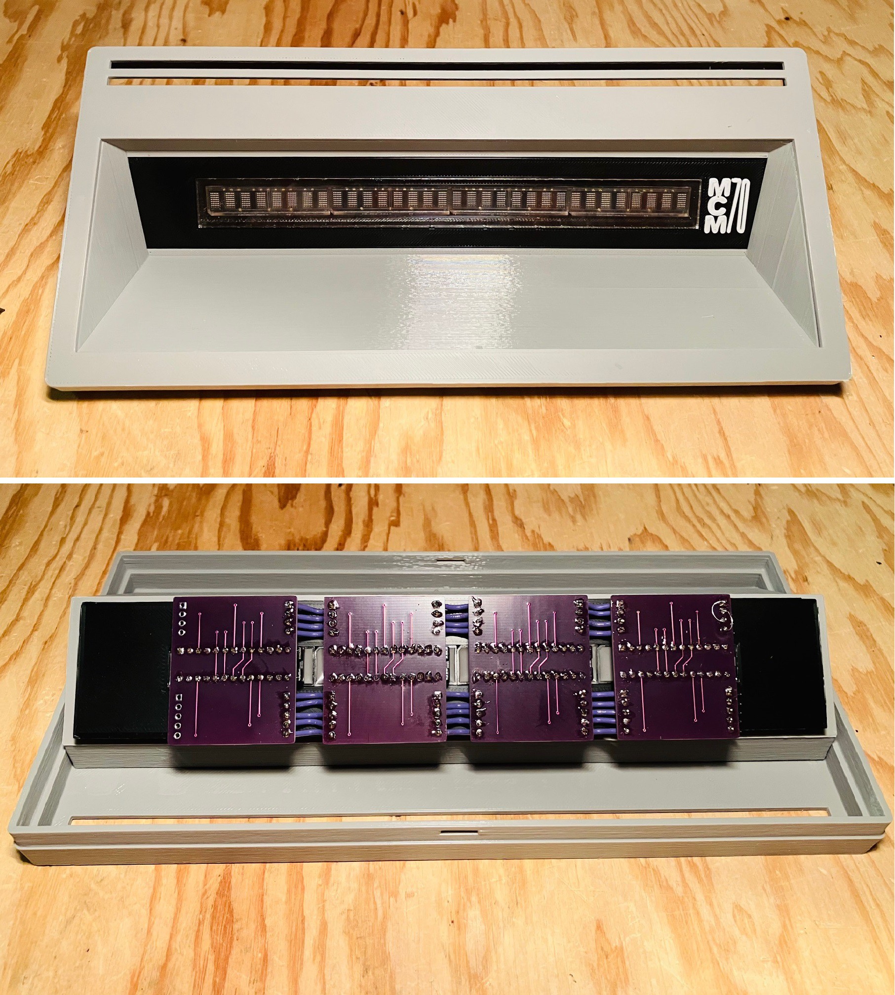
Display Assembly
05/25/2022 at 21:41 • 0 commentsFinished the display assembly. It's ready to pop into the case when that's done.
![]()
-
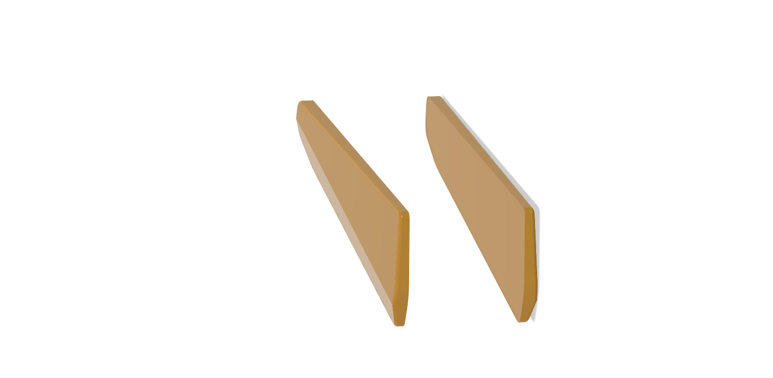
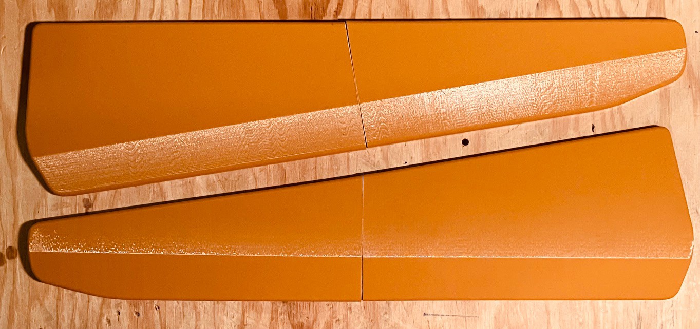
Side Panels
05/25/2022 at 20:43 • 0 commentsI mentioned that to my surprise the side panels for the MCM/70 were injected molded plastic, so I decided to 3D print them. It took a bit to get the models to my liking based on the photos I had, but in the end I was happy with the results. Here are my models.
![]()
And this is what they look like printed.
![]()
Time to start putting together a frame.
-
York University Computer Museum Visit
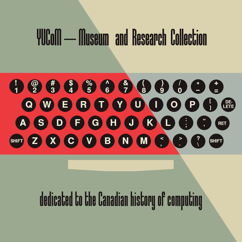
05/11/2022 at 16:49 • 1 commentLast week I had the pleasure of visiting the York University Computer Museum (YUCoM). I was greeted by Zbigniew Stachniak (Ziggy), curator of the Museum and author of the book "Inventing the PC - The MCM/70 Story". The museum is about an hours drive from my home in Waterloo Ontario.
![]()
As the above poster indicates the museum specializes in Canada's contribution to the computing field.
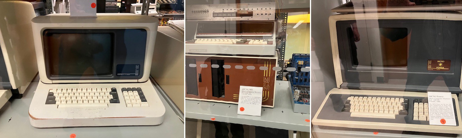
The museum has a small selection of their large archive of Canadian computers on display. Since I was interested in the MCM/70 I first focused in on some of the other MCM models that they had on display.
![]()
From left to right: MCM/900, MCM/800, and an MCM Power.
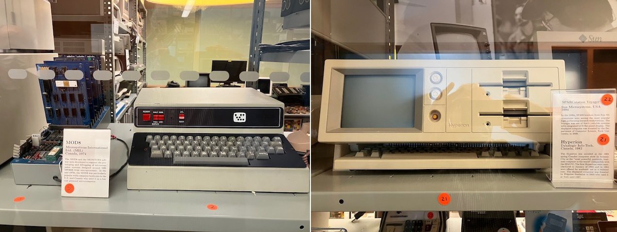
There were a few other exabits that caught my eye.
![]()
On the left is a computer based on the MIL 8008 microprocessor, a Canadian version of the Intel 8008. In the middle is a very early Volker-Craig terminal. VC terminals were manufactured in Waterloo and designed by a couple of University of Waterloo grads Michael C. Volker and Ronald G. Craig starting in 1973. They were very popular at the University of Waterloo when I was there (1977-1982). On the right is a Hyperion, an early portable computer thought to be the first portable IBM PC compatible. It was marketed by Infotech Cie of Ottawa.
After a brief tour I got down to business taking a good look at the MCM/70 on display.
![]()
I took many photos as I would be modelling the MCM/70 case based on them. One surprise was that the side panels, which I thought to be made of wood, are actually injection molded. I would never have realized this had I not had access to the real thing.
While I was taking my pictures Ziggy and I had a great talk about the machine; he is probably the world's leading expert on the MCM/70. I especially enjoyed our conversation about the emulator that he wrote for the MCM/70. Since the intent is to use the emulator for research purposes he spent a lot of time making sure that it worked precisely as the hardware did. Since he had a couple of MCM/70s available to him he was able to validate the emulator's faithfulness to the original. We were also able to compare emulation techniques since I wrote an emulator for a Sol-20. Nothing like spending an afternoon geeking out ;-)
So now I have what I need to get going on the MCM/70 case. Ziggy has graciously offered to provide more information should I require it. I foresee spending a lot of time working with Fusion 360 over the next couple of weeks.
-
Update 2022-05-01
05/01/2022 at 23:50 • 2 commentsThe project is at a bit of a pause right now while I wait for stuff. Dave from osiweb.org is currently out of OSI replacement keyboard PCBs. He is having some manufactured but it could be a couple of weeks. I'm reluctant to do any work on the keycaps until the keyboard is done. I have not as yet been able to obtain measurements for the MCM/70 so I can't begin modelling the case. If anyone knows of an MCM/70 out there please let me know.
While I'm waiting I have been making a Sinclair ZX80 clone based on [Cees Meijer]’s excellent writeup (also see: A ZX80 WITH A PROPER CASE).
MCM/70 Reproduction
I am making a full sized MCM/70 reproduction, a Canadian personal computer from 1974.