GOAT INDUSTRIES
-
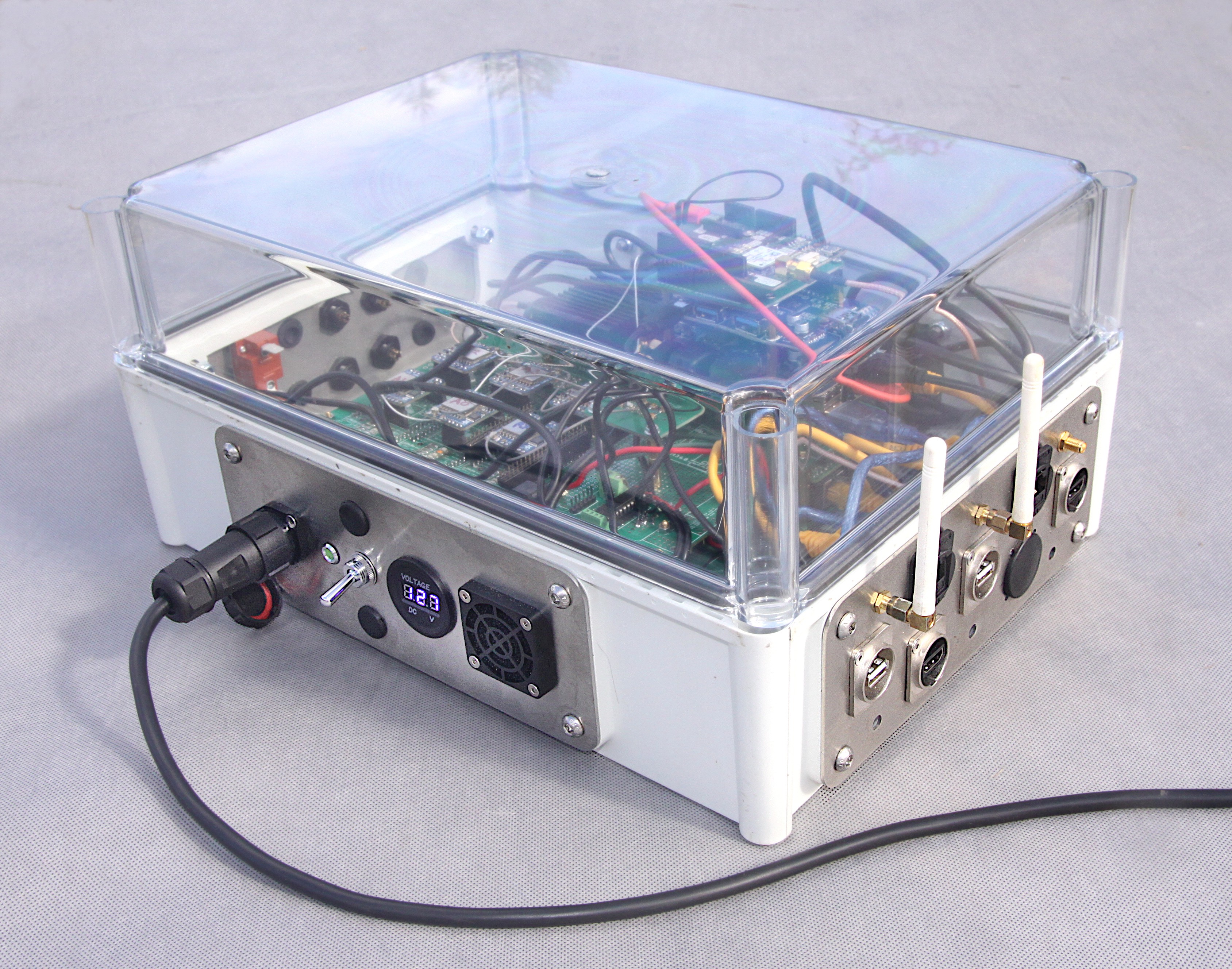
Weather Proof Box for the Machine Based Unit
09/24/2022 at 12:11 • 0 commentsFancy custom made stainless steel panels were drawn up in LibreCAD and ordered from my local laser cutting factory. Files are available here: https://github.com/paddygoat/quadROSbot_2022/tree/main/Enclosure . These allow not only ethernet connection, but USB and HDMI ports for debugging of the Pis on the machine if necessary. If deployed to Mars, Martians could use them for watching Netflix.
![]()
-
Proof of Concept Achieved !!
08/01/2022 at 20:55 • 0 commentsYay ..... The system now has four LoRa modules sending data to another set of four modules in parallel!
In the previous update I had one module working at a spreading factor (SF) of 7 and bandwidth of 500 KHz transmitting every 5 seconds or so. Now I managed to ramp up the SF to 9 and pull down the bandwidth to 125 KHz, with a similar transmit time. Strangely, no parallel programming was required, even though the modules themselves run in parallel, which is a bit counter-intuitive. During testing, other than actually getting a GPS 'Fix', I developed some simple indicators to check that the data was coherent such as detecting non - standard characters, checking for missing data chunks and measuring the time taken to transmit each chunk. The sleep time in the python script that performed the task of breaking the data down into chunks set the overall rate of the whole system and was simply the time recorded for each transmit divided by four. Having plenty of Blinkenlights available was useful and red LEDs were flashed on the receiver side every time a data chunk was missed - which was thankfully very rare!
The whole system could now be scaled up to get the maximum perfermance out of the LoRa modules ie a SF of 12 and this would required about 32 x 2 modules (SF 9 = 4 modules, SF 10 = 8 modules, SF 11 = 16 modules, SF 12 = 32 modules). However, it's getting to be expensive and for the time being tests out in the wild can be done with the current 2 x 4 set up. The next step is to sling the dog controller into a suitably sized enclosure and bolt it onto one of my robots ...... Hmmmmmn ..... which one will I choose ??
-
PCB Layer Cake
07/17/2022 at 18:22 • 0 comments![]()
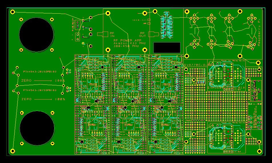
In this latest iteration of the basic design, the large PCBs from PCBWay were stacked 2 high as shown above, but if we count all the PCB layers, there are about 7 in total which will give a total of 12 LoRa radio modules. But this is not the end of it, more of the large custom PCBs can be added to extend the LoRa modules by 6 for each PCB added. This entails A LOT of 3mm brass stand offs and USB hubs and very kindly, Liam at PCBWay sponsored this project by supplying these aforementioned components and the large PCBs for free. Thank you Liam !!! Nonetheless, the LoRa modules are quite expensive, as are the 'MEGA 2560 PRO Embed CH340' modules that control them and so I chose initially to test on just four modules working simultaneously which should also make programming a bit easier to start with. I also had a bit of a scare with the MEGA 2560 PRO modules as in one batch about 50% were defective. Fortunately, this problem was solved by simply removing one of the 3 pronged voltage regulators which got crazy hot after a very short time. If anybody else comes across this problem - just remove the component that gets hot with a soldering iron. Obviously the module can no longer be externally powered other than by USB or 5 volts, but this project does not need to do this.
Getting back to the Layer Cake, on the bottom we have one of the large custom made PCBs from PCBWay. The next layer is the MEGA 2560 PRO modules which can be seen and the Master Rasperry Pi and the MPS 8A 5V power supply which both cant be seen in this photo. The 3rd layer up is another large custom PCB and the 4th the LoRa modules which are at the same level as the slave Raspberry Pi. 5th layer is a 5 way USB hub. The 6th a Raspberry Pi to Arduino footprint adapter and the 7th layer a fancy Ublox F9P GPS module. These layer cakes are in pairs and there is one, with the joy sticks fitted, that sits in the control room, or 'Nest'. The other requires no joy sticks and sits on the machine, the 'Dog', wherever that might be. The whole point of this project is to get correction data transmitted in parallel from the Nest to the Dog ..... so the next challenge to to upgrade the software with some parallel processing!
-
Microcontroller Choice
06/18/2022 at 14:00 • 0 comments![]()
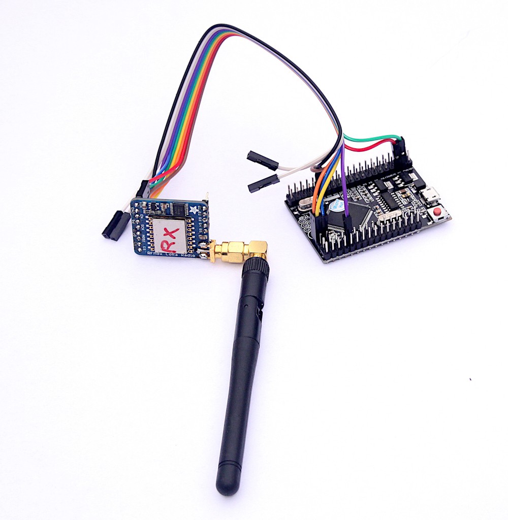
Well, actually, in the end the Heltec ESP32 module could not be made to work with ROS and LoRa simultaneously :( I'm sure it's possible, but I ended up spending too much time on it and decided to go for an Arduino Mega 2560 Mini Pro instead, which worked straight away without any messing about. The end solution is a bit more expensive as there is no onboard LoRa chip, but time is also precious!
It's now time to get another run or PCBs made and incorporate a few more handy features such as the ability to turn the power on/off to the RPis from one of the micro-controllers and get auxillary power via Type C USB cables.
![]()
-
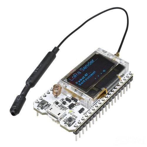
Testing Heltech LoRa ESP32 Modules
06/14/2022 at 10:39 • 0 comments![]()
Although the name suggests these devices might be hellishly difficult to work with, it actually only took me 2 days to get it working with ROS via WiFi and initialise a LoRa session. The boards look incredibly well made and, best of all, they have a blue LED on GPIO pin 25. To get all features on the device working Heltech have produced their own IDE tool chain and part of it is used in the Arduino IDE and, strangely, this software only works on an AMD 64 type PC running Ubuntu v.20. Ubuntu 18 does not have the USB driver required, although I guess they could be tracked down and installed manually. It was also tested on a Raspberry Pi, but failed. Having data sent to the ROS could be a lot less hassle although I'm wondering how many of these devices can be used at the same time without clogging up the local WiFi radio spectrum. Should I rebuild the PCBs with slots for 10 of these gadgets ..... or maybe 20?
-
Data Now Flowing Through the LoRa Airwaves
06/05/2022 at 16:14 • 0 commentsFinally, after many days of coding and decoding, I got data flowing from the Nest through the LoRa airwaves to the Dog. Not only that, I managed to get a proper 'Fix' on the Dog Ublox ZED F9P. At the beginning, it took about 120 seconds for one chunk of fix data to get sent, which equates to about 3,000 bytes. These chunks were split up into about 85 packets of about 45 bytes each. After messing about with the LoRa code, and various settings such as spreading factors and bandwidths, I got the chunk transmit time down to about 4 seconds and only then did the F9P get a proper fix. I'll now be slowing increasing the spreading factors until the transmit time starts to get affected and the Dog starts to detect missing packets and bleeps it's buzzer at me, but I've got a feeling that the system is already running at full tilt. However, even if this is the case, all is not lost as it's more than possible to add a whole load more radio modules to the system - dial it up to eleven! (One for Dog Tx and ten for Dog Rx and ten for Nest Tx and one for Nest Rx). This would give 10x the speed and the opportunity to increase the spreading factor for longer range.
-
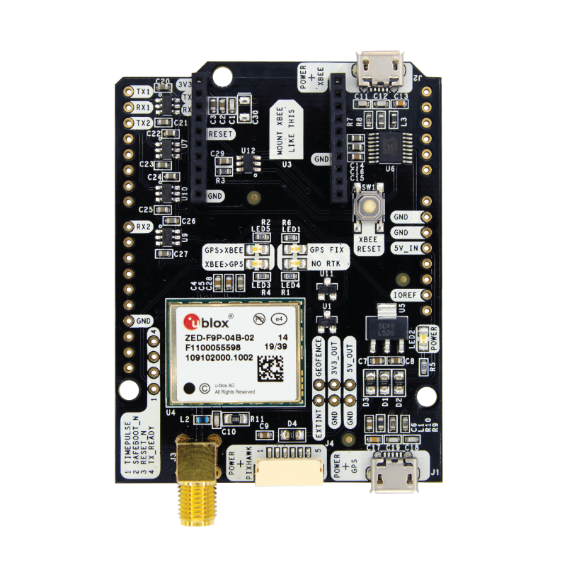
Accurate Satellite Positioning
05/31/2022 at 09:40 • 0 comments![]()
Probably the most important task for long range machine to machine communication is to know exactly where our roving machines are, and even the stationary ones. In many cases, ordinary GPS/GNSS satellite positioning would be fine, giving an accuracy of about 2 metres for a moving machine. The accuracy of a stationary machine can be much better if thousands of readings are averaged over 24 hours or even a whole week. To get the positional accuracy of moving machines to an acceptable levels, correction data needs to be sent to the machine (Dog) itself for it to calculate an accurate position for itself, which can then be transmitted back to Mission Control (Nest). The idea of correction data is a slightly abstract concept and has a few logical fundamentals to be aware of:
- Data sent from satellites travel through the Earth's atmosphere, which causes the time component to vary slightly causing a subsequent small error.
- This error can be largely corrected for a stationary module in the Nest by taking an average of many thousands of readings over a whole week.
- We now know the exact position of this one module located in the Nest.
- The Dog is roaming around within a few miles from the Nest and so the data from the satellites goes through pretty much the same chunk of Earth's atmosphere as the Nest.
- The error for the Dog and Nest is pretty much the same.
- The Nest module knows exactly where it is, so it also knows the error at any given time.
- If the Nest can send the error details to the Dog, then the Dog would also know the error and so be able to correct it's own position.
Fortunately, the Ublox module does a lot of the work for us and all we have to do it to configure it to export the correction data if the module is in the Nest and import it if it is on a Dog. Configuration files are available in the Github repo. The Ublox configuration is done on a Windows computer running the free Ucenter app, which is quite vast and may take a bit of time to navigate - but it's quite fun to see all the satellites buzzing about the sky and the true positional accuracy of our machines.
Normally, we'd just get a radio module for the Ublox module, bolt it on and job done, but I chose to take control of the correction data and route it into a LoRa module for long range transmission. I wanted to have ROS enabled in all the machines, so it was logical to get the data moving trough the ROS, which proved to be quite 'interesting'. In a previous iteration , we used RTKLIB and it's str2str app, which worked really well through WIFI, but with very limited range. Getting the data moving through ROS meant changing it from ASCII characters into HEX format, changing HEX into a string, and then splitting the HEX string data into packets of size 45 characters each. The data is given a 'start' and 'finish' flag and then gets relayed to an Arduino MCU through ROS which is then transmitted through LoRa, one packet at a time with additional data such as signal strength and such like bolted on. It's quite satisfying to see the data come over on the Dog and the process for getting the received data into the Dog's Ublox module is just a matter of reversing what was done in the Nest.
If anybody's interested in the actual code that handles this, it's located in a file called: nest_slave_talker_listener.py in the custom made nest_slave_talker_listener ROS package. Serial data is handled very nicely by the Python Serial library.
-
Can documentation be fun?
05/29/2022 at 10:13 • 0 commentsNormally, in the recent past, I'd create a device or machine with all manner of fancy Ai equipped all seeing, all thinking, super fantastic sensation that even worked really well. But, and this is the big one, by the time I'd finished, I had pretty much no idea what all the components were, especially when it came to interactive files in the software stack. In one project, I ended up with a pretty crazy diagram showing how all the files interacted, but it just was not properly accurate for my liking.
One of the problems is that I like to work really fast and focus entirely on getting the project working. This time I am taking a more leisurely approach and am trying to create enough documentation to enable myself, never mind anyone else, to see how it was all pieced together. To do this, the documentation stages need to be enjoyable.
Due to previous experience in this particular field, I pretty much know 95% that this project is going to work really nicely as it is built on top of other previous successful projects. I believe that by doing the project a bit more slowly and methodically could be MORE enjoyable and taking a bit of time out to do some documentation could actually make it MORE fun and rewarding.
The first step in this new adventure is to keep track of the software stack as more files are added and not to lose track of how files interact with each other. Currently, as of May 2022, the stack is quite simple but, as the project evolves, this is likely to change quite radically. If I start iteratively updating the stack diagram after each major change, can I accurately keep track of it all? I am going to try, at least!
The diagram below is the second iteration - it's the second diagram I have produce so fat detailing the components of the stack. It's going to get much bigger as time goes on.
![]()
The eager eyed amongst us will notice that the stack is split into 2 halves and the right hand side is currently empty. So far, I've been working exclusively on the 'Nest' which is my own term for the control centre, or 'Mission Control' in NASA lingo. The choice of words for parts of the stack and the system in general is absolutely crucial as in previous projects I saw terminology, especially with regards to satellite positioning, deteriorate into a travesty of inappropriate descriptions. Other projects ended up with multiple use of the word 'base' which resulted in truly incomprehensible instructions. 'Base' is a banned word in this project and all parts of the system are to be described by objects in the animal kingdom including 'Nest', 'Dog' and 'Snout'. Nest is used to indicate that the device or part of the stack is physically located in the mission control room. We could then have Nest_Master to indicate that the device is the master in the ROS operating system in the Nest. Dog is a roving machine and dog_snout is the front of the machine. Trust me, this form of nomenclature is infinitely better than what seems to be the industry standard.
In the diagram above, the most crucial details of the stack in the nestmaster and nestslave are shown. Both these devices are Raspberry Pi V4's. There's also currently just one Arduino Mega 2560 called arduino_master_tx. I should probably re-name this to arduino_nest_tx in the next iteration of the documentation for extra clarity. There's also going to be an arduino_nest_rx to handle incoming radio waves from the dogs and any other machines out in the wilderness.
Another thing that might be slightly interesting, is that I will be backing up the SD cards or SSD's or whatever, regularly throughout the development so that there will always be at least 2 copies of each Raspberry Pi system. Also, the plan is to have fully duplicated SD cards (or whatever) for the main Raspberry Pis so that, for example, the Master SD card will contain all the files for all the Masters that exist in the entire ecosystem. Logically, I should probably change the word nestmaster to masternest, this being the case. This may sound trivial, but having properly logic defined names massively helps understand the system. The nomenclature of the system is constantly evolving at the moment!
Long Range Machine Control System
LoRa + ROS Full Duplex Peer to Peer Data Transceiver Array with Onboard High Precision Satellite Positioning