-
Counting seconds. Accurately.
04/23/2022 at 20:48 • 3 commentsI don't know if you ever tried to measure time with a microcontroller ? It's quite good for order of magnitude, or for comparing several duration, but when it comes to precisely keep track of the time, it's another story entirely. Let's have a look at what solutions are available (in an Arduino context).
You can use millis().
No, it's a joke.You can use a dedicated timer and its interrupts. The first step in the right direction. Most (if not all, I don't know !) microcontrollers have hardware timers. On Atmega 328p (Arduino Uno, Nano, etc.) you have three timers, two 8 bits (timers 0 and 2) and one 16 bits (timer 1). The first is used by millis(), the second is used by the Servo library, if my brain serve well (in french that would be a pun ! Servo / cerveau), the third by Tone. PWM uses either of the three, following the pin you want to use.
A 16 bit timer seems to be a good choice to keep track of the time. You can use the prescaler to make it tick every seconds, or you can use it at its fastest speed, count overflows and at a regular interval change the overflow value to get a round count to one second. By using this, you soon discover that your resonator doesn't run at 16MHz, but more to some 16MHz-ish speed. Ok, no problem, you just need to compensate it by comparing against a known accurate time. But then you realize that the clock that was too fast ten minutes ago is know too slow. And we are talking about several seconds over ten minutes. Dead-end. The main problem here is that microcontroller boards use resonators as clock, not quartz. And their precision is far from good on long term. We are talking about ±0.5% absolute precision and ±0.2% drift with temperature. 0.2% is 172 seconds per day, or 7 seconds per hour.One side note : when using this kind of visual synchronization, you also quickly realize that most of the devices you think are precise, are not that much. On my smartphone the 59th second of every minute is only half a second, I believe that every minutes it receives a reference tick from my network or the service provider. Between those reference ticks it relies only on its internal circuitry, which boils down to the resonator accuracy exposed above. My computer is not a good choice either : With a simple processing sketch, I can visually measure quite a difference between the processing update, which seems reliable, and the clock update on my taskbar.
The first thing that comes to mind when you've tried this is "use a RTC module ! They are readily available for a few euros (or dollars if you count with them), and they are made for keeping track of time". Yes. That's what I did. Maybe I was unlucky, but the one I tried was far from beeing anything near reliable. several seconds drift per hour. Maybe they (DS1307) can be calibrated, but the datasheet doesn't explain how.
On Atmega 328p, if you read the datasheet, you learn that the microcontroller has an internal 8 MHz oscillator that it can run on (that should be enough for a clock !) and the datasheet claims that it can be very accurately calibrated by the user. Promising ! You can indeed calibrate this oscillator, and the difference is immediately visible. I've stopped at "this value set on the calibration byte gives a too slow clock, but the value immediately above is too fast". I don't know if it's stable on long term, because I couldn't have a frequency that is multiple of a second. The calibration process I've used, exposed hereafter, could make it a valid choice. Need to test it one day.
On atmega 328p again, if you read the datasheet further, you also learn that Timer 2 can run asynchronously. That is, it can take its reference from the same clock as the CPU, but it can also use another one, like a pulse input on a specific pin, or an external resonator. If you correlate this with the previous point, that means that you could run the whole microcontroller on its internal clock at 8 MHz, and use a 32.768 kHz crystal to clock the Timer 2, that you will use as a reference for the clock. It still have a noticeable drift, but this time it can probably be calibrated. If watchmaker have known how to do this for 50 years on wristwatch, I believe it can be made on a modern microcontroller. Honestly I don't know if it works, I stopped at this calibration problem on the Atmega 328P...
But use the exact same thing on the Attiny 816 ! The main difference are that the Attiny is a much modern controller, which can run at 20MHz on its internal oscillator at any voltage, and that it has a RTC timer for exactly what we want : counting time. It should be straightforward. Yes, almost. Handling registers on modern Attiny is a bit different than on Atmega. No big deal, the datasheet is quite clear. Except on one point : the naming of the bitshift constants for each register bytes. Hardcoding works, but it's less portable. Configuring the timer is quite easy once you've read the datasheet. There are a few examples on Internet, and I'm pleased to see that where Atmel had Applications Notes covering specific points of working with their chips (both for soft and hardware), microchip continues this traditions with Getting Started tutorials on how to use this or this part. Here you learn the bare minimum to wake the RTC, and also that your crystal needs two charge capacitor, which were not needed on Atmega chip. You soon have a chip that has a reliable timer, that drift for a few second per hour, but that drift uniformly. That leads to the last part :
Calibration ! The crystal I used on this project is the most accurate I could find at Mouser's. It runs at 32.768 kHz and has a ±15ppm tolerance (that is, it less than 0.5 Hz deviation from the reference frequency). So, which way can we calibrate it ?
One solution is to set the time, let one day pass, and check the drift after 24 hours. It's long, and relies on the ability of the user to be precise enough.
One other solution is to do the same thing using a computer. I've wrote a short Processing program to that : send an arbitrary byte to start a counter on the clock, let ten minutes elapse, then send another byte to stop the counter and request its value, and compare it to the one in the Processing program. There is at least two drawbacks with that approach : if I make several clocks (which I plan to do), I have to let my computer alone for long times, and more importantly, you can control how the USB sends packets, so In the end you're not controlling the accuracy of the calibration.
The solution I used is quite easy : use a GPS as the reference clock. GPS modules are available, they are quite cheap, and they are very accurate. Plus most GPS ships and modules have a "1pps" (one pulse per second) output. That's great, with this e can trigger an interrupt and have a reliable way or calibrating our system !
The algorithm I came with is quite simple, is processed in 30 seconds, and is divided in two parts :
On each tick of the GPS clock, the RTC current value is sampled. The current sample is compared with the previous one, and the cumulated drift is computed.
After ten seconds, the average drift per tick is computed, and this value is added or subtracted to the counter top value.
The drift is again measured with the new counter top value, this time over 20 seconds. Then the cumulated drift is again computed, and two values are determined. One is a correction to apply on a regular delay, and the other is the delay.
With these values known, the main program can now count ticks, and every n ticks it will add or subtract a given value to the counter. The value are of course saved to EEPROM, so on next startup a calibration will not be needed.
With this simple calibration, accuracy of half a second drift per day is eaisly obtained, which is quite good, and as good as, or even better, than most watch and clocks available on the market.There is still room for improvement. Better calibration can probably be made by simply let it run a bit longer. Another thing is that crystal drifting is dependent on ambient temperature. Attiny, like Atmega, have a temperature sensor channel on their ADC. This could be used to monitor temperature and compensate calibration accordingly.
Finally, there is one thing that can be made : moving the GPS reference clock from its breadboard to another freeform object ! And that will probably happen soon.
-
Design choices.
04/23/2022 at 15:01 • 0 commentsIt's been a long time since I wanted to give a try at freeform circuits (or circuit sculpture, call them how you like). And preferably a clock, because it's probably the most obvious thing can be useful in everyday life. In fact, the clock should have an old calculator VFD display. The ones I saved here and there will one day come to life again.
So. Clock, freeform. Freeform, but there's a catch : I'm quite lazy. Planning something too complex was the best way to start nothing at all. And a display, two shift register, a microcontroller, quartz, photodiode and amplification circuit, plus a safety cell start to be something complex, at least if every connection has to be hand made, and hand shaped. That's roughly 120 wires to cut, form, etc. Plus, I love the esthetic of PCBs. Making a PCB that groups functions on several individual boards could be a good base for several different geometries, and that will easy the freeform assembly.
![]()
![]()
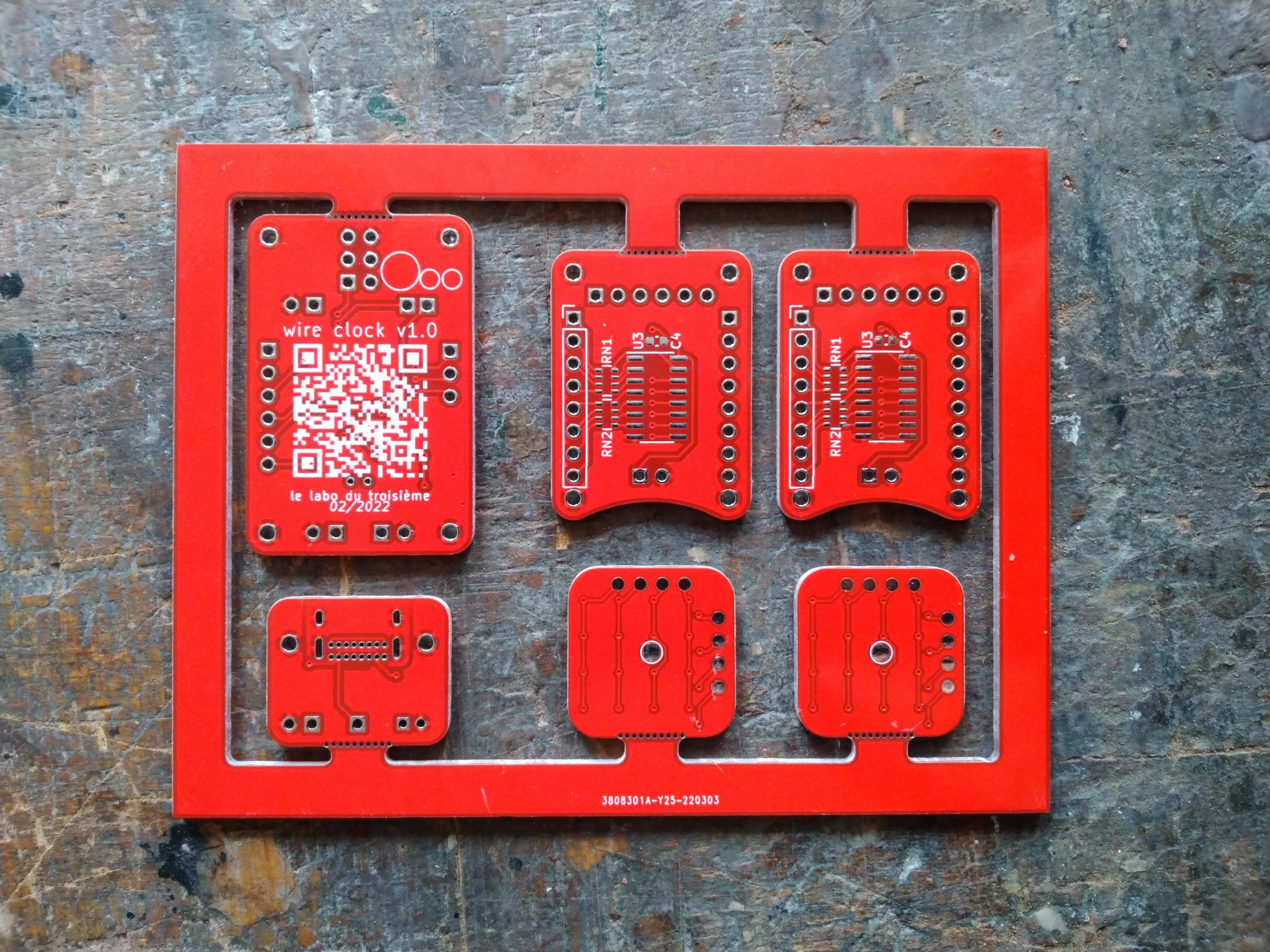
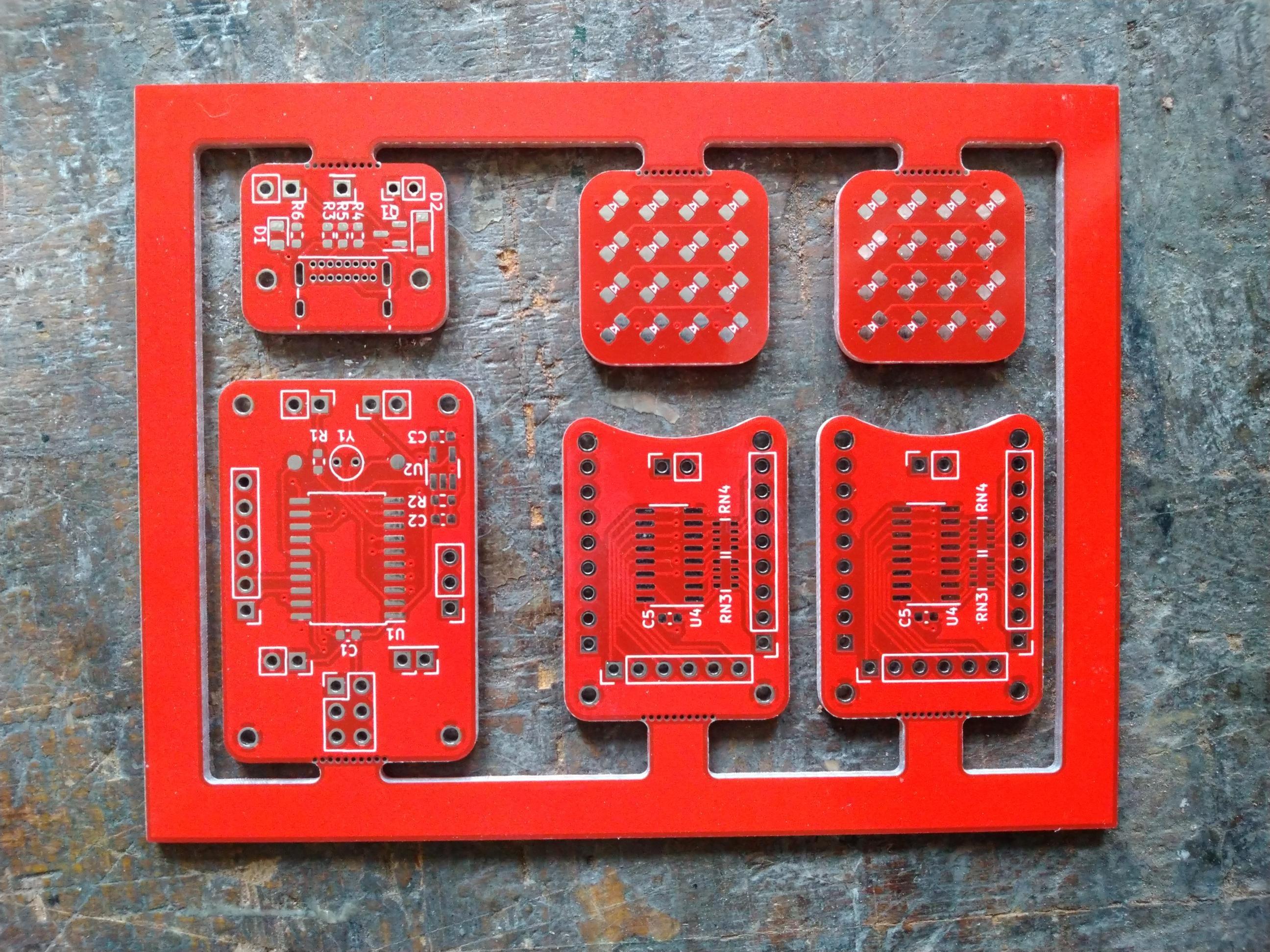
The circuit has been subdivided in three (four) different circuits :
- Main board. This contains the Attiny 816. Side note : I was planning to used an Attiny 1616 instead, but you've maybe heard of ship shortage ? That's this thing that makes you design a board not following the functions you need, but what you can source before two years have past. Seriously, for some projects I work on, we had to revise the design not to correct bugs, but to accomodate for different references or footprints that are available...
Attiny 816, connectors to other boards, crystal (dedicated log to come), photodiode and its amplification circuit. There is also a UPDI port for programing, and while I've followed Microchip recommendations for this footprint, I should not have. On next revision I'll use the three pin connector recommended by SpenceKonde of MegaTinyCore (which is the Arduino plugin used for programming the Attiny series 1). The three pins have two advantages : less real estate used, and it's symmetrical, so can be used from both faces. And I quickly realized that it's not useful : it's essential, given how constrained space can become on this kind of project. :D
There are three connections for buttons, to set time. I didn't know while designing PCB what would be those buttons, so I just provisioned ports. They could be capacitive buttons, classic tact buttons, or freeform. After all, a button is a device that shorts a circuit, so let's be creative ! On future revision I'll probably add a button board : I don't like capacitive that much (mostly because I prefer the tactile feedback of a button), and "wire buttons" do not inspire confidence. - Power board. Quite straightforward. A USB port. It's the first time I use USB C connector. They are available in a wide variety, from completely implemented USB C to power only, with USB 2 in between. On this board there is a power led, a provision for connecting a coin cell for data saving in case of power loss, and a few resistors (USB C asks that you place pull-down resistors on CC1 & CC2 lines when replacing USB B or micro B).
- Shift register boards. There are two of them. One is used for providing VCC to each segment, the other to provide GND connection for active digit. The SR can be mounted on either side of the board, the output ports are symmetrical. The idea is that two boards can face one another, the inputs pins are aligned (except of course the data pin, as they are chained), and each output pin face a non-connected pin on the other board. That way the two boards form a strong assembly with 16 wires forming two 8 bits "data bus", going from their pins on one board, to "mechanical" pins on the other. And following how we want to place things in space, SR can be mounted to either face.
The drawback of this is that the boards virtually becomes a "two-sided one-side PCB", as there is no room for vias. At least on the size I wanted not to exceed. It contrains the port to map the SR pins one on one. Initially the connection were supposed to match with the main board. That's no longer the case, but that adds a bit of intricacy to the wires. - Lastly, there are two little square board. I'm always sad (kind of) to have some resources not used. That's the case here : with a 4 digit display, there's only half the outputs of the shift register used. I wondered what I could do with the remaining, imagined 32 leds bargraph (that I even designed in Kicad), or two 16 leds bargraphs, before I realized that 16 is 4x4, and settled for two 4x4 matrix. That end up not beeing used, as you can see.
A final note : I would never have designed such a circuit made of several different boards without a fantastic tools, Kikit. It makes panelizing almost as easy as blinking an eye. It's been mentioned on Hackaday, and you can find the reference here. I really owe Kikit to have unleash the potential of what can be made with PCB.
- Main board. This contains the Attiny 816. Side note : I was planning to used an Attiny 1616 instead, but you've maybe heard of ship shortage ? That's this thing that makes you design a board not following the functions you need, but what you can source before two years have past. Seriously, for some projects I work on, we had to revise the design not to correct bugs, but to accomodate for different references or footprints that are available...
-
Why is there a 8x8 matrix display at the top ?
04/23/2022 at 08:37 • 0 commentsYou may notice that while I mention a seven segment display in the description, and in other logs, there is no such display on half of the pictures of the clock. There is a reason to that.
A few weeks back, there was a beautiful project shared on hackaday, about a big led matrix becoming a smaller one (and another form factor) thanks to fiber optics. I've really loved it, and as I was planning the first clock I thought I had to try to display time on a seven segment display, from an 8x8 led matrix, using fiber optics. Ordered some fibers, some small 2x2cm matrix display, and wait for them to arrive.The clock has been assembled with that in mind : the led matrix on top of the clock, and one fiber optic going from each dot of the matrix to one segment of a 7 segment display. Each column of the matrix would be a digit, the lines would be the segments from A to G plus the decimal point. Displaying hours, minutes and seconds would use six of the height columns. That's two columns not used, which could stay off, or could display random patterns to add blinkiness, or be routed to other places to display other informations (am/pm, alarm, etc.)
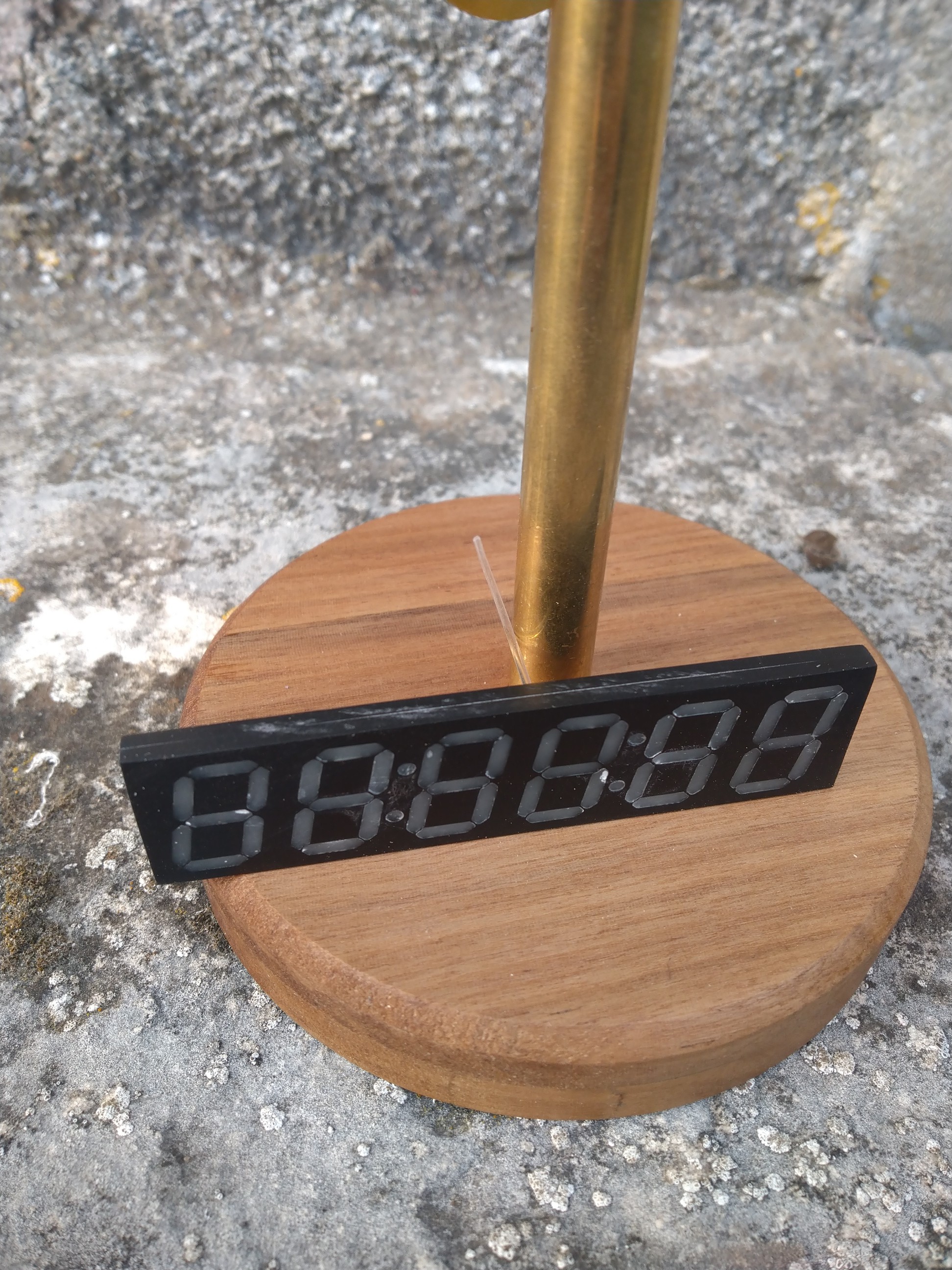
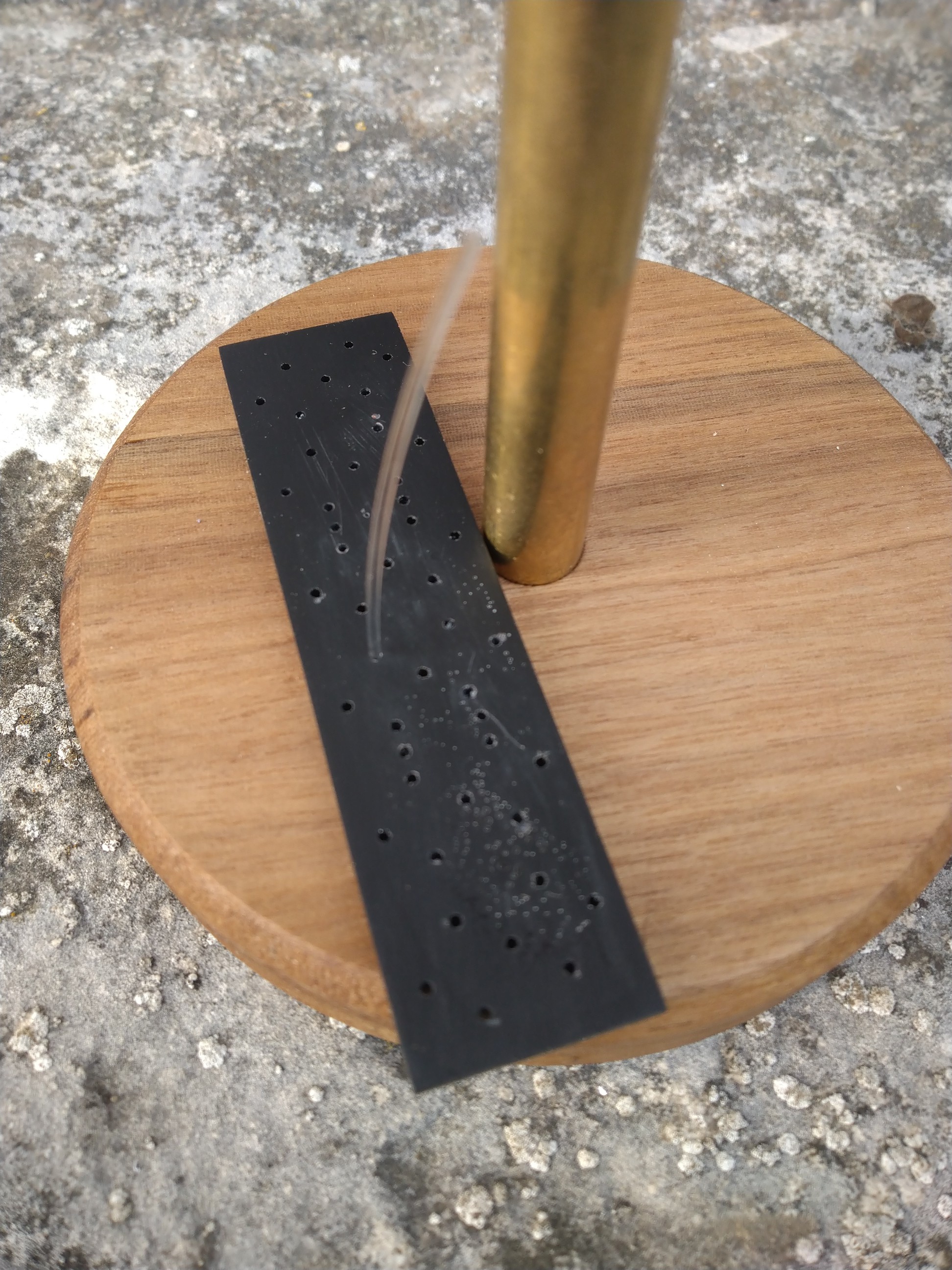
The seven segment display has been made with 2mm acrylic sheet, cut with CO2 laser. It's about the same shape as any commercially available display, it just shows 6 digits and two double-dot separation. It's composed of two layers : on the front layer are segments shapes, on the back one are 1mm holes at the center of each segments. Both layers have been glued together (soldered is the right words as it's assembled with chloroform), then a white diffusive PU resin has been poured into each segment. The idea was that the fiber should go through the hole, and diffuse into the resin.
![]()
![]()
Unfortunately, it doesn't work. At all. The resin is probably too much opaque, or too thick, to properly diffuse light. There might be too much loss into the fiber. Or at the ends of it. The leds are also probably not powerful enough. I believe it could work, but it would need more tries.
So I just add a "real" 7 segments display to it. I've kept the 8x8 matrix, because it looks cool. And as they are wired together, you can literally read each byte for each digit. Plus seconds. :)
-
Using shift registers to drive 7 segments displays.
04/22/2022 at 11:14 • 0 commentsA few years ago, I made a timer for photographic processes (which you can find information about here, and that is available here), which also has a 7-segment display. On this board the display is handled by the classic MAX7219 driver. Although it works very well, this chip has a kind of drawback : it's quite pricey, something like 9€/piece when bought by 10 at mouser's. That's half the price of all components I have for this project, for one of them ! And almost four times the price of the Atmega 328p running the board.
Of course, one can bought them on aliexpress / Ebay, they are much cheaper there. But are either counterfeit, or recycled, and not everyone of them will work.
So, I wanted to replace this component by something cheaper. Two shift registers should work, don't they ? This was one of the things I wanted to test with this project.
The first thing I wanted to be sure of is if they could be multiplexed. Shift registers are often used to drive 7 segments displays, but with one SR per digit, and as many SR chained as there are digits. It seems a waste of resource, as you could theoretically use of them to drive segments, and another one to select digit. The only thing is that the one used for digit selection would have inversed logic, so ts can sink current. So be it. It works perfectly, with one drawback (I'll come to it later).Another thing I wanted to know : all programs or libraries I've read that use shift registers use bit banging. The protocol they use is quite close to SPI, so I wanted to try and use. There are two pro and one con.
- The first advantage is that there is no function to write : just use a SPI library. One line of code for init, and one for each byte you want to send. Bonus : there are four SPI modes, one beeing the exact timing we need to drive a 74HC595.
- The second pro, and the most important to me, is that on most microcontrollers there is a SPI hardware driver. So you just have to handle the bytes you want to send to the hardware, and can do something else in the meantime. Ok, the Arduino SPI library writes the byte to the SPI driver, but waits until the transfer is over, so the benefice of it is quite light.
- The con is that as there is no slave select line on the shift register, you cannot use the SPI bus with any other device, as any data exchanged on the bus would appear on the SR. In this case this is not a problem since there is only one device on the line, but it could be.
On the Arduino Nano I first tested it, the bus can be run at 8MHz. On the clock I've used the same clock frequency, but the chip runs at 20MHz, so 10MHz for SPI clock should be possible.
Last thing : on my timer I offer the user to set the brightness he needs. Could it be with serial registers too ? I supposed yes, as there is an OE (output enable) pin. If we apply PWM on it, we should be able do dim the brightness, yes ? Well, it works really well too. The only thing to take care of is that the OE pin is active low, so the PWM duty cycle is reversed. If using Arduino's analogWrite(), you just subtract the duty cycle you want from 255, and you're good. If working with hardware timers directly (that could enable a 16bit resolution), you can chose the pin behavior (set on 0, clear on compare, or clear on 0, set on compare). On Attiny series 1, it's even simpler : you can invert logic for any pin by setting a bit in setting register, so when you write 1 to this pin, it goes to 0, and vice versa.
Here we are : two shift registers used for driving a 7-segments display, with hardware SPI, brightness dimming. There are a few things to note, though :
- The global brightness is less than with a MAX7219. That maybe because of the multiplexing (but MAX7219 also multiplexes its output, so I don't thing this is the cause), but also about the value chosen for led series resistances. I'll have to give a try with other resistance value.
- The brightness is not the same for all numbers. 1s are far brighter than 3s or 0s. I think this comes from the shift register limitation : IT's sn74HC595 datasheet gives a max continuous current source / sink of 35mA per pin. It's ok, we are far less than that. But the max current through VCC or GND is 70mA, and here we probably demand more. A mosfet on each output could be a solution to handle more current and have an even brightness on the display, whatever the numbers displayed are.
- There can be a flicker when PWMing the display. With a refresh frequency of 1kHz (i.e. each millisecond the next digit is updated) the flickers disappears. I believe it's due to an interference between the display refresh rate and the PWM frequency.
That's all for today !
 Pierre-Loup M.


