Ruediger F. Loeckenhoff
-
We did it! 25 Boards Ordered.
10/19/2022 at 18:35 • 0 commentsWe really did it! 25 boards are ordered and confirmed. This includes assembly at PCBWay. We will only have to solder the batteries and the TVS diode which wasn't available there. Wish us luck that the design proves to be flawless. It should be - it is called V2.0 for a reason. Yet I need to apologize that I couldn't keep the $25 price tag. Including taxes and shipping from Hong-Kong your fair share of the costs will be $40 – with all the risk at our side. Without the generous sponsoring from PCBWay it would be $50. But hey! This is a tracker controller that could run a 100 m2 tracker or more and it includes all the required sensors without any extra sensor cabling. And once we have the open source hardware files online, anyone can order it for that price directly from PCBWay or wherever.
For me this is a great day: High precision solar tracking control can be regarded as a solved problem!
This doesn’t mean that there is nothing left to do. Ermanno is designing a probe card board for upload and testing right now. I will have to figure out the test routine and print the jig that will hold all the boards. Probably we will make those parts open source too. Finally I will have to perfect the tracking with the new sensors. The magnetic sensor has less noise but the tilt sensor more than the MPU9250. This will be easy compared to the work performed. Finally we will make efforts to let people know. A good rank within the hackaday contest would certainly help. And of course we will tell our partners in the CPV community.
-
Make it an I2C device for RasPi robotics!
10/12/2022 at 14:56 • 0 commentsI am presently writing a detailled description of the board and I realized how usefull the second I2C port of the ATMEGA328pb may be. It allows you to turn the whole board into an I2C slave for a Raspberry Pi. You can controll the motors of a two wheeled robot (digger) and set servo positions through I2C. On the other hand, the board can constantly read the compass chips and RTC and provide the results in registers for the RasPi to read. I am getting more and more confident that the board can be a hit!
-
Leo Stelzers Project
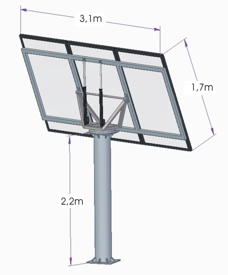
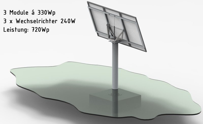
10/09/2022 at 21:02 • 0 commentsLeo Stelzer sent me some very nice pictures of the solar tracker he is planning for in his garden and allowed me to repost them here. I hope you will keep us up to date with your progress.
![]()
![]()
![]()
-
Not just for Solar Tracker Control - Hack it
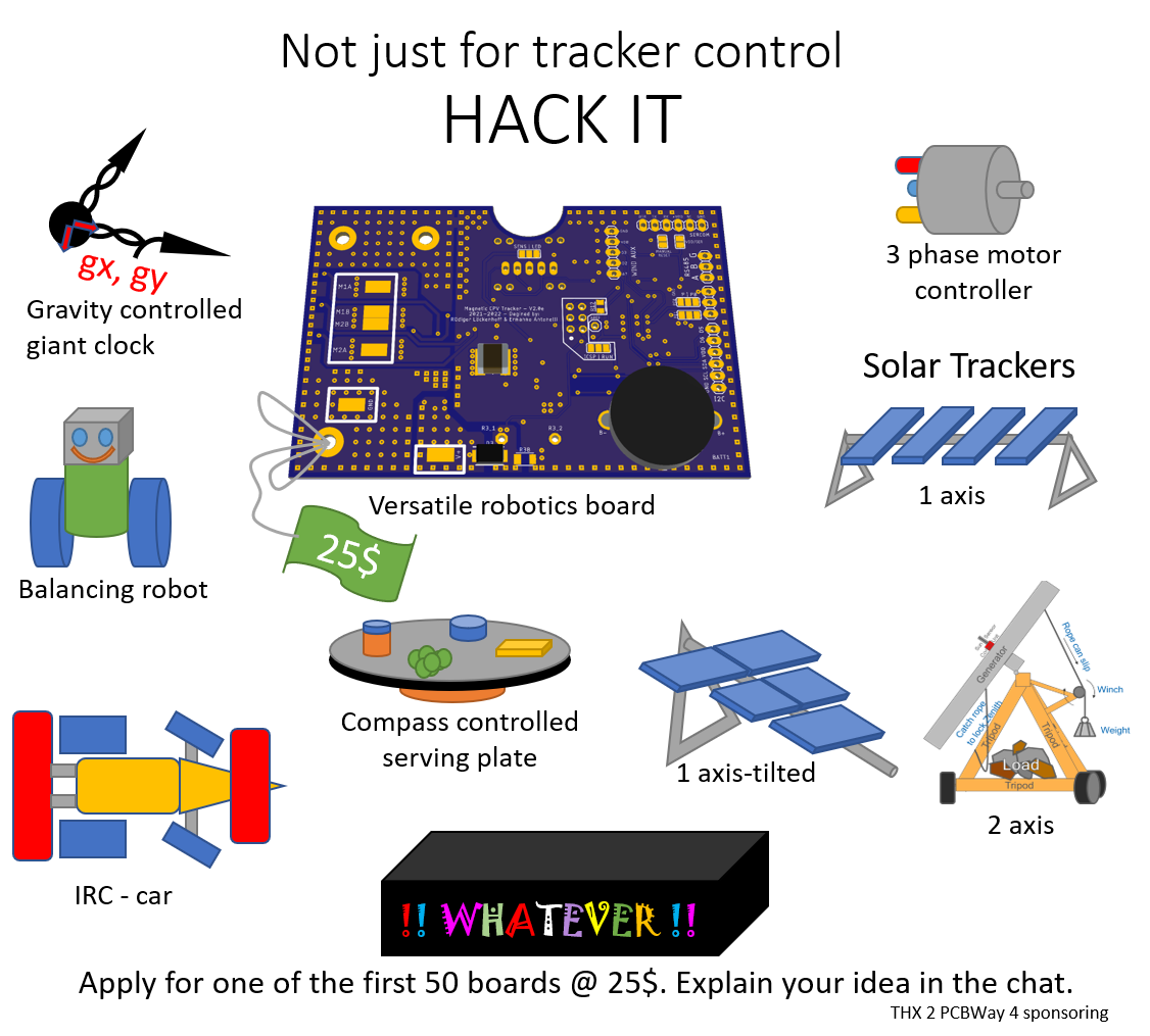
10/08/2022 at 08:38 • 0 commentsWe have a new vision! We want this board to become widely available through many shops in Asia and anywhere. It should become the standard solution for solar trackers and we want to build an active community around it. Solar tracking alone won’t do that trick and it doesn’t need to. It’s not just a tracker controller, it’s
A GENERAL ROBOTICS BOARD
It’s an ATMEGA 328pb board with a powerful 24V 8A 3-phase motor controller that can also be used to run two DC motors at different speeds at the same time. The inbuild accelerometer and magnetometer allow for orientation sensing without external sensors. The RS485 communication and the real time clock are ideal for remote automation. There is also a current monitor to detect abnormally high currents. And there is the 4-channel light sensor connected to ground or VDD with pullup/pull-down resistors. Two I2C ports are available externally together with all unused pins of the µC. We are not aware of any other board with such versatile components. And all this will be available
AT A PRICE AS LOW AS $25. NOW IMAGINE WHAT YOU CAN DO WITH THAT!
The board is ideal for building up a community because it will make the replication of your projects so easy. There won’t be any sourcing issues because most things you need are already on the board. Just make the external connections and upload the code. We will love to see what you will come up with. Here are some cool ideas.
![]()
NOW THIS IS STILL ALL ABOUT SAVING THE WORLD
But why shouldn’t you have fun in the process.
APPLY FOR IT NOW!
Explain your idea in the discussions section!
Our sponsor PCB-Way will sponsor this first set and will allow us to give the parts away for $25. So, you can get it now for a price which will only be reached again in mass production! Apply for a piece in the chat and explain your idea. We cannot wait to hear about it! If you want to build a solar tracker – even better. You will just have to wait some extra weeks until I have perfected the code for the new sensor chips. The code and the board drawings will be open source soon. We promise!
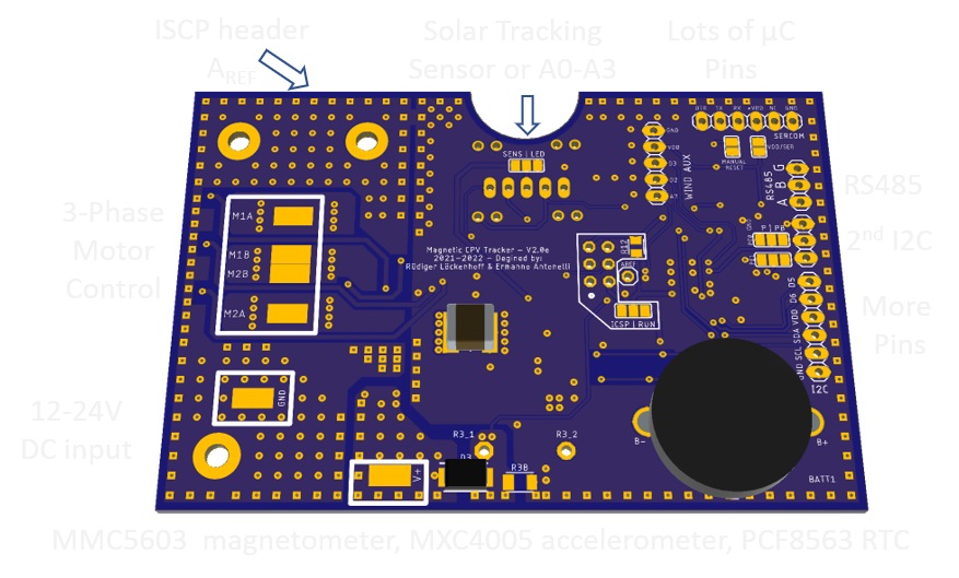
Now here is a preview of the board with all features explained.
![]()
-
Plans for the shading beam sensor.
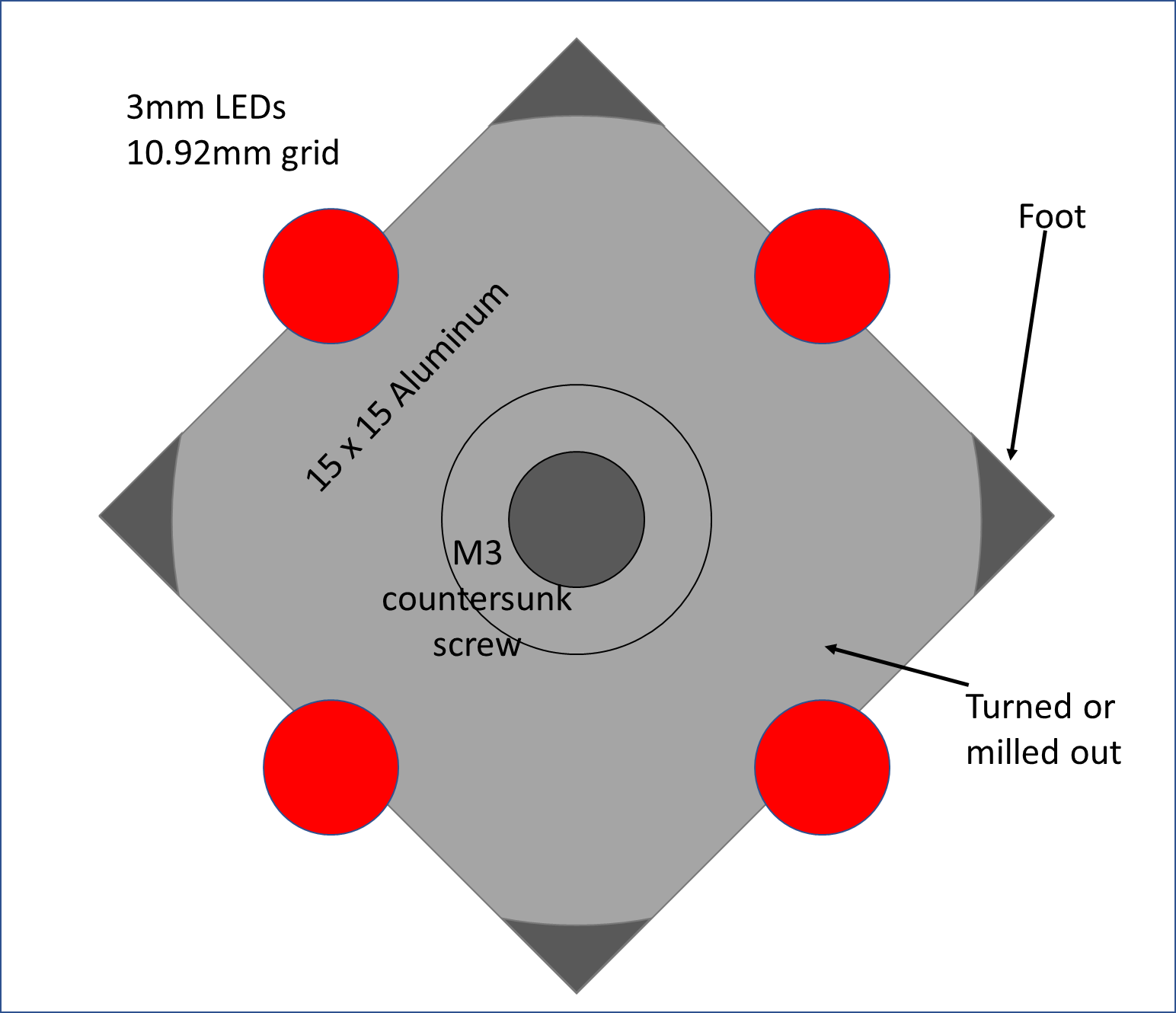
10/03/2022 at 09:35 • 0 commentsErmanno has been working on the board and designed it such, that the sensor may either be an imaging sensor by AZUR SPACE solar power or it may consist of 4 LEDs as photocells in a grid with 10.92mm spacing. Now I had to come up with a shading beam arrangement that fits these sensors.
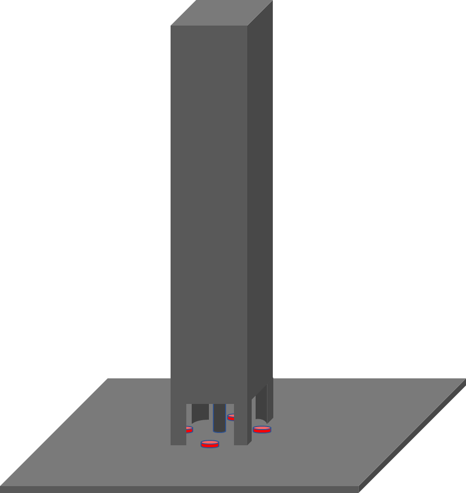
This is my solution. 3mm LEDs will be set into holes within the front plate with a central hole for a countersunk screw. A 15x15mm aluminum beam will be screwed on top as a shading beam. Please see the sectional drawing through the top surface of the aluminum plate and the isometric side view below.
The shading beam is secured to the mounting plate of the controller with a countersunk screw. The LEDs are ground off such that they are still protruding from the plate by about 1mm. This arrangement will ensure that water and dirt can pass over the LEDs and dirt cannot build up. Only a leaf or a bird dropping will disable the sensor. I will need to make sure, that such an event is reported to field control over RS485.
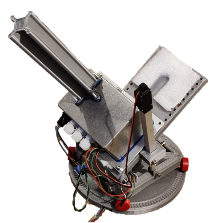
Here is an earlier version of the shading beam sensor on the desktop tracker I used for "living room table software development". It has a 3d-printed shading beam. That remains an option too, but I prefer a simple, sturdy metal part for extended outdoor application.
The advantage of this shading beam sensor will be its availability and simplicity. On the other hand, the AZUR SPACE sun sensor will be more sensitive and much easier to clean. It is basically a 4 pixel camera and I am describing it in detail here:
https://aip.scitation.org/doi/pdf/10.1063/5.0101466
In particular, it will be beneficial in a tracker field where cleaning trucks with rotating brushes run along the CPV sun trackers to crean the modules. The shading beam may get damaged but the flat front glass of the "4 pixel camera" will just be cleaned. Have a look here, to see what I mean:
https://www.sunbrushmobil.com/en/
In any case, Ermanno found a PCB layout which accomodates both versions of the tracking sensor, so you can choose. We are rapidly approaching our final design.
-
Magnetometer arrived - all parts are working! (Almost) ready to order final boards.
09/28/2022 at 21:09 • 0 commentsI received the MXC4005 and added it to the two other breakout boards. It all works together without any issues. I am reading time from PCF8563, magnetic field from MMC5603, acceleration from MXC4005. I am a bit disappointed about the MXC4005. It works very well in x and y but has a -0.4g zero offset in z. I can correct for it in the code during calibration. But yet I expected it to be a bit better. The signal is also quite noisy. Up until now with the MPU9250 (accelerometer + magnetometer) I needed to do oversampling for the magnetometer and a single read of the accelerometer was enough. With the MEMSIC sensors it seems to be the other way round.
In any case, the MEMSIC parts are available and comparably cost effective, so we will continue in this direction and deal with the issues of MXC4005.
**** All parts are tested in combination ****
**** We are ready for the final boards ****
Ermanno is already working on the last changes.
Side issue:
What I do like about the MEMSIC parts is their simplicity. You just set a the sensitivity in the registers and start reading. In comparison, the successor of the MPU9250 is ICM20948. It needs a lot of work in the I2C registers before it even starts working. I made it work by evesdropping on the library of Wolfgang Ewald "Wolle" and just banged out the bytes in succession with a delay in between where it was necessary. I couldn't use "Wolles" library itself because it ate away to much of my 32kB program space of the ATMEGA328. The ICM20948 is also quite expensive and has 52 weeks delivery time. Today you apparently need to source by availability. With the MEMSIC parts which are readily available in highest quantities at good prices we made the right choice - even so they are a bit trickier concerning assembly and calibration (in case of MXC4005).
-
That's what we have
09/25/2022 at 07:49 • 0 commentsThis is a contest and you deserve that I show you all that we have.

It doesn't look like much and that's the whole idea. To the right you can see the tracker control board with the sun sensor at the bottom. The motor cables extend to the right and the 24V supply to the top. In the center of the picture there are two breakout boards that should not be there. One is the old MPU9250 and the other an MMC5603 magnetic compass. The problem was that the MMC5603 magnetometer and the MXC4005 accelerometer are sub millimeter in size and just not hand-solderable. So presently I am using the old MPU9250 tilt sensor and the MMC5603 magnetometer. In a few days I will also receive the MXC4005 breakout board and I will connect it in parallel to the other breakouts for testing. Once this is done, Ermanno can finalize the board and we will have it made by our sponsor PCBWay. By then, the small breakout boards will be gone and we will have a couple of final boards.
They are meant for testing by anyone who is interested and who can make us believe that he/she has a real project in mind.To the left you will probably recognize an Arduino Uno with a MAX485 breakout board. Yesterday I successfully demonstrated a half duplex communication between the boards. We wont have the final board at the end of the contest but shortly after - I promise.
As you can see the board will be approx. the size of an Arduino Uno and capable of controlling up to 50V, 8A = 400W. That's enough for a 100 square meter solar tracker - if you absolutely wanted to go big. I demonstrated a tracking precision much better than 0.1° in an earlier project log.
-
RS485 works, board is fully tested
09/24/2022 at 21:40 • 0 commentsI almost lost my nerves trying to figure out the RS485. The task sounds simple. The field control should send a “Ping” to the tracker and the tracker should answer with “Pong” when it received the “Ping” correctly or with “Piep” if it didn’t get it. It didn’t work. The problem proved to be that with RS485 in half-duplex there must always be a device that controls the line. When the line is loose, a lot of gibberish is coming in. Once I understood that problem, I made sure that there is an overlap when both devices control the line. First, the field control asks the tracker for data and still controls the line to give the tracker time to react. The tracker also takes control of the line and for an overlap time no device tries to send data. When the tracker has waited long enough to be sure, that the field control has released the line, it sends the requested data string.
Now here is the printout from the "field control" that sent the traffic to my computer through the normal Arduino Serial port. It doesn’t look like much but it certainly took a lot of time.
Ready for a match!
Ping_Pong
Ping_Pong
Ping_Pong
…Now the Ping can be a request to a certain tracker to send data. The Pong can be that data.
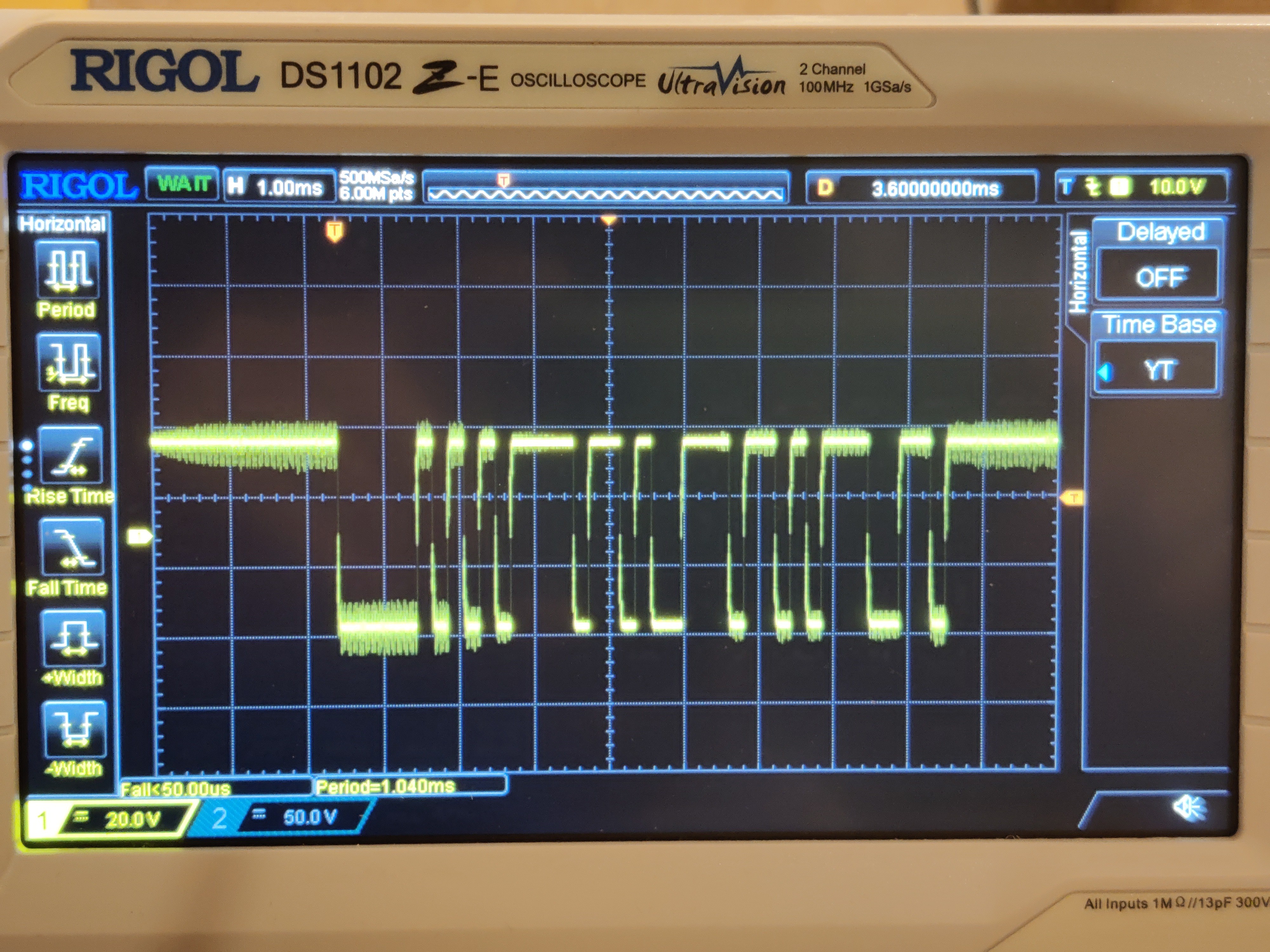
This is what the "Ping" looks like on the scope:
![]()
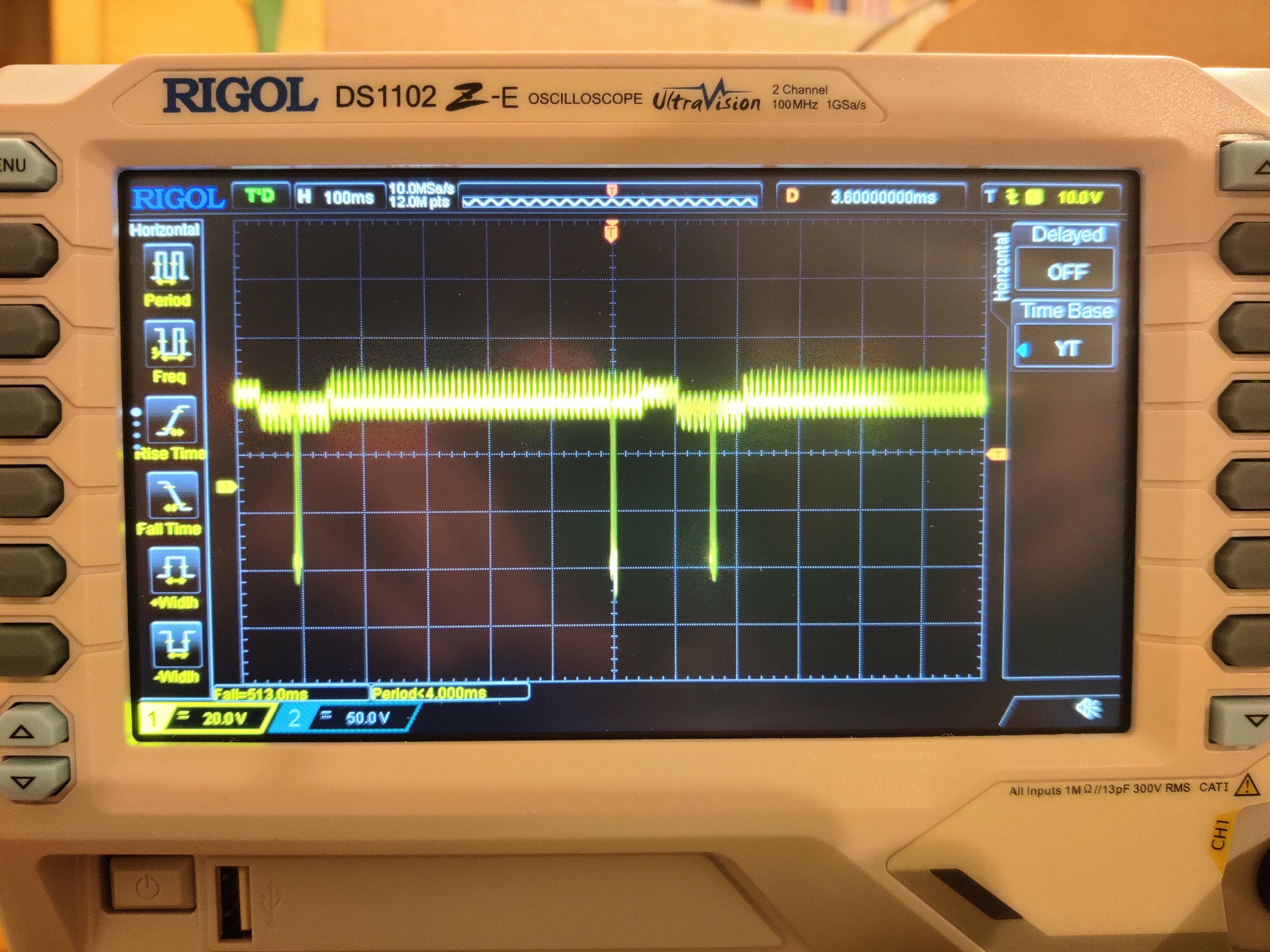
And this is the Ping_Pong where you can see some differences between the voltage levels of the two RS485 chips.
![]()
At the time of the trigger (middle of the screen) the field control holds the bus. Then, both RS485 chips control the bus together. Then the tracker controls the bus alone to sends its "Pong" and releases it after a short while to the field control again.
Now the present board is fully tested and working fine and I am waiting for the new tilt sensor as the last part missing. When this is working too, Ermanno can get the final version of the board ready to be produced by PCBWay, who offered to sponsor us in this way. Exciting! We are so close to a professional all in one board solution.
-
Motor Control and Current Measurements work very well.
09/24/2022 at 13:40 • 0 commentsMotor controller and current measurement
This will be a long log, so I want to summarize: The motor controller of the “single board” works as expected and we can get a current measurement which is good enough to detect blocked or damaged gears and motors. We can transfer these readings to a central field management computer via RS485.
Adjusting and checking the PWM
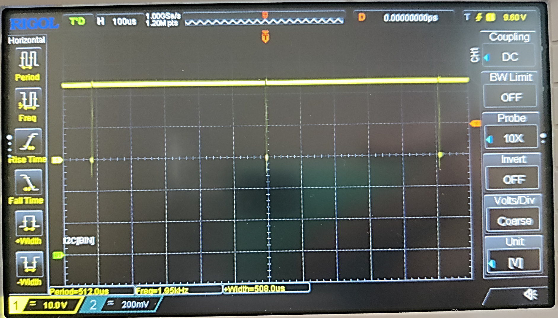
I had 3.9 kHz at 16 MHz clock speed for the open source tracker. So, I expected this to reduce to 1.95 kHz at 8 MHz clock speed. My expectation was correct.
![]()
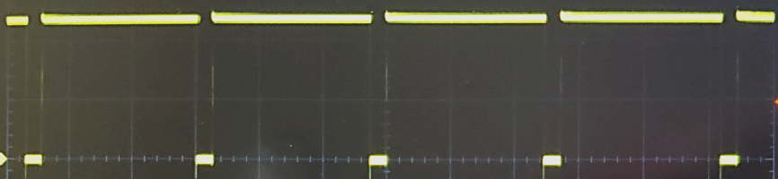
This is full speed. We are using a DRV8300 bootstrap driver and the small dips are necessary to recharge the bootstrap diodes. Without these dips, the driving voltage of the upper FETs in the half bridges would collapse.
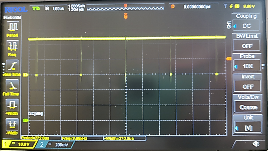
Now, I wanted to increase the PWM frequency to 3.9 kHz again by adjusting the timer pre-scalers for the PWM timer (I am using timer 1). This almost worked out. I guess, I am losing some time somewhere in the interrupts. 3.68 kHz is good enough.
![]()
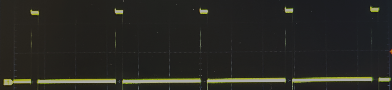
Motor speeds can be chosen from 1 to 16, where 16 is full speed as seen above. Now I tried speeds 1, 8 and 15. Everything works as expected.
![]()
![]()
![]()
Perfect! Well done, Ermanno (who figured out the DRV8300).
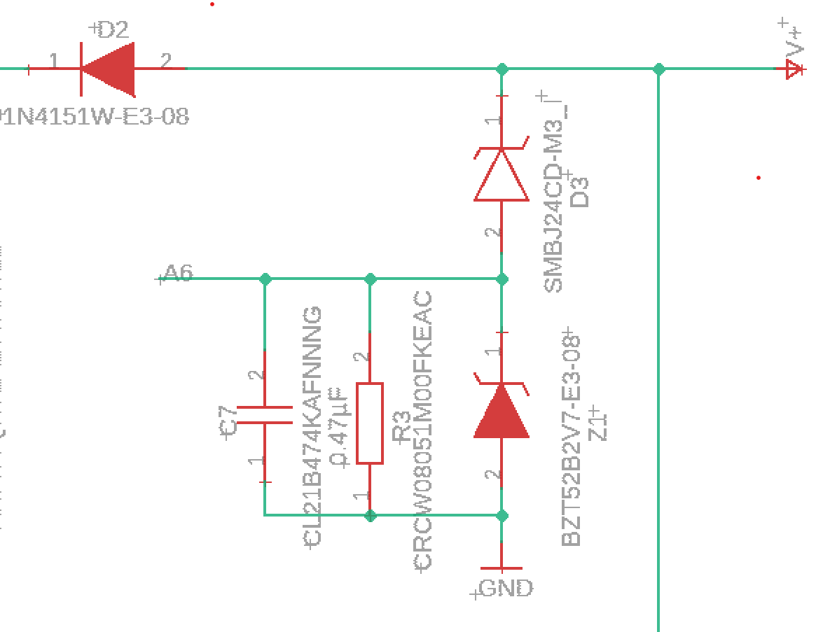
Now I should explain, how we are doing the current measurement. Please have a look at the schematic below.
![]()
The current is coming in from the right at e.g. 24V. The power supply and the cable are inductive. On the other side, the circuit is drawing power in pulses, especially as far as the motor controller is concerned. When current through an inductivity is interrupted, a high voltage pulse is generated. We don’t want that, because it can fry the MOS-FETs. So we either need to use an input capacitor or an overvoltage surge protection diode. We decided for the latter. It is basically a 26V Z-Diode (SMBJ…). It will absorb voltage spikes and thus we loose a tiny amount of power.
Now, it’s not a bug, it’s a feature! We yet need motor current monitoring. So let’s measure the spillover current through the Arduino Analog ports. This yet requires a measurement shunt an a filtering capacitor as well as another Z-Diode (BZ…) to protect the analog input ports.
Now that’s unconventional. Will it work?
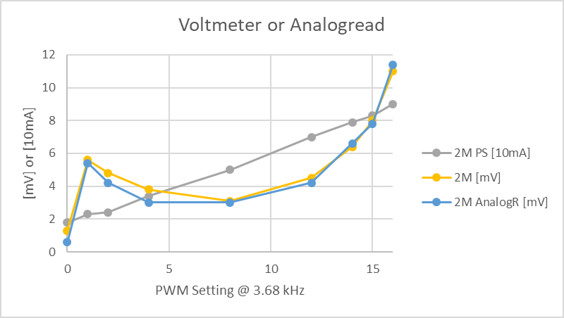
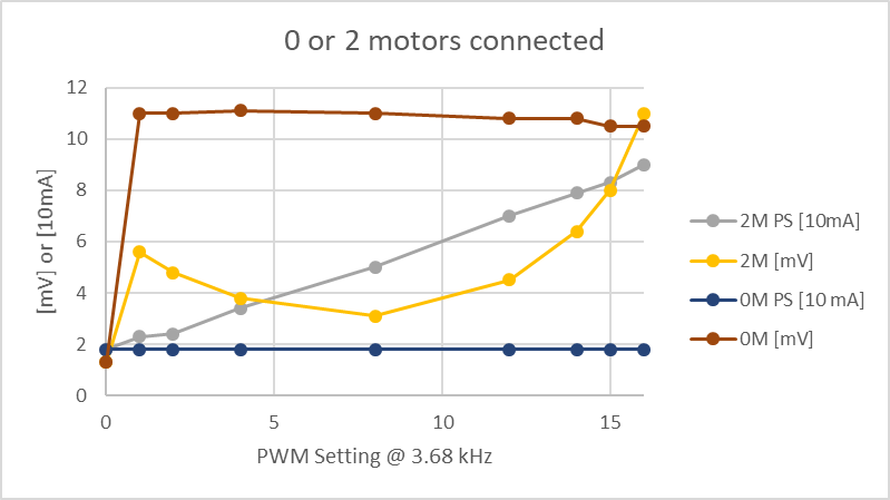
First I want to show you the following graph:
![]()
“2M PS [10 mA]” is the power consumed by the whole circuit which I read from the power supply. 2 motors “2M” are connected to one output to give me a bit more power consumption. The circuit without motors running consumes 18 mA which corresponds to “1.8” in the graph. Now I sped up the motor by increasing the PWM duty cycle from 1 to 16. The power from the supply increases more or less linearly. “2M [mV]” is the voltage at the 0.47µF capacitor read with a voltmeter. This corresponds to “2M AnalogR [mV]” which is the value obtained through the analog port with 10 bit ADC and an internal reference voltage of 1200 mV. 1100 mV is standard and 1200 mV is still in the allowed range for the ATMEGA328. Yet I rather guess that the measurement error is caused by the impedance of the voltmeter when I measure mV by hand. When I try to stop the motors, the analogRead value increases a bit.
First Conclusion: it kind of works!
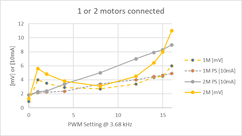
Yet the shape is a bit strange. Let us compare the mV reading for single load (1 motor) and double load (2 motors).
![]()
So when two motors are connected, the reading at the 0.47 µF capacitor increases at any PWM duty cycle. That’s good, that’s expected!
Now, here comes the surprise. This is the comparison between no motors and 2 motors connected.
![]()
Apparently, the bootstrap driver generates spikes when no motor is connected and thus we read 11 mV at the capacitor even when no current is drawn from the motors. This doesn't mean that we would see a higher consumption at the power supply.
Now, please note that I used tiny motors for testing which draw 25 mA at full speed. So, realistically, the current in the field will be 100 times as high, i.e. in the range of 2.5A. The voltage signal of the motor will be in the range of 500 mV. The 10 mV signal from the bootstrap driver will not matter much anymore. I need to find a bigger motor. The maximum reading at the capacitor is limited by the 2.7V Z diode which protects the Arduino analog port. If 500 mV is 2.5A, then 2.5V at the Analog input would be 12.5A. This is more than our 8A FETs can handle. I guess, the current monitoring is amazingly well adjusted. If we yet wanted to change it, we just need to swap the 1 MOhm resistor in the schematic by some other value.
-
magnetometer works
09/22/2022 at 19:55 • 0 commentsThe new magnetometer works perfectly as a breakout board. We just could not place it by hand. It has less noise than the MPU9250 and also seems to be faster. I have it working on the present version of the circuit board and I am using the MPU9250 tilt sensor. So the Memsic tilt sensor will be the next piece to add as a breakout board, then we will be done with testing and move on to the final version of the all in one circuit board.
Open Concentrating PV Solar Tracker Controller
Achieve better than 0.1° sun tracking accuracy with a compass a tilt sensor and a shading beam sun sensor.