Close
0%
0%

OpenDendrometer

monitor the health of trees and fruit

Similar projects worth following
The OpenDendrometer solution provides insights on critical plant health information. It is a valuable tool for studying and managing plant growth.

OpenDendrometer can help answer questions such as:
Is a tree experiencing water stress?
Has tree growth rate slowed?
Is fruit growth rate on track for harvest?

A dendrometer is an instrument used to measure diameter changes of trees and fruit. Small micrometer changes in diameter occur in trees and fruit throughout the day as part of healthy water transport processes. Comparisons of these daily changes in diameter can help predict the onset and occurrence of water stress. In addition, diameter measurements collected over weeks and months can reveal the rate and magnitude of plant growth. 

The OpenDendrometer is a low-cost digital dendrometer with wireless data transfer capabilities. In simplest terms, it is device that measures, logs, and wirelessly reports changes in linear displacement. It uses commonly available electronics components and fabrication techniques to ensure that others can easily build their own OpenDendrometer. All design files and information are shared freely.

OpenDentromter_EN.xlsx

OpenDendrometer Engineering Notebook, 2023-05-03

sheet - 11.22 MB - 05/04/2023 at 00:17

Download

OpenDendrometer_v0.5.ino

OpenDendrometer Arduino Sketch Sv0.5, 2023-05-03

ino - 8.27 kB - 05/04/2023 at 00:21

Download

OpenDendrometer_v0.2_KiCad_20230503.zip

OpenDendrometer Ev0.2 KiCad project files, 2023-05-03

x-zip-compressed - 374.32 kB - 05/04/2023 at 00:18

Download

OpenDendrometer_Ev0.2_PCB_Schematic_20230503.pdf

OpenDendrometer Ev0.2 PCB Schematic, 2023-05-03

Adobe Portable Document Format - 99.85 kB - 05/04/2023 at 00:20

Preview

OpenDendrometer_Ev0.2_Gerbers_20230503.zip

OpenDendrometer Ev0.2 PCB Gerbers and Drill File, 2023-05-03

x-zip-compressed - 72.65 kB - 05/04/2023 at 00:20

Download

View all 8 files

View all 22 components

  • Board v0.2 Received, Assembled, and Tested

    John Opsahl12/04/2022 at 04:39 0 comments

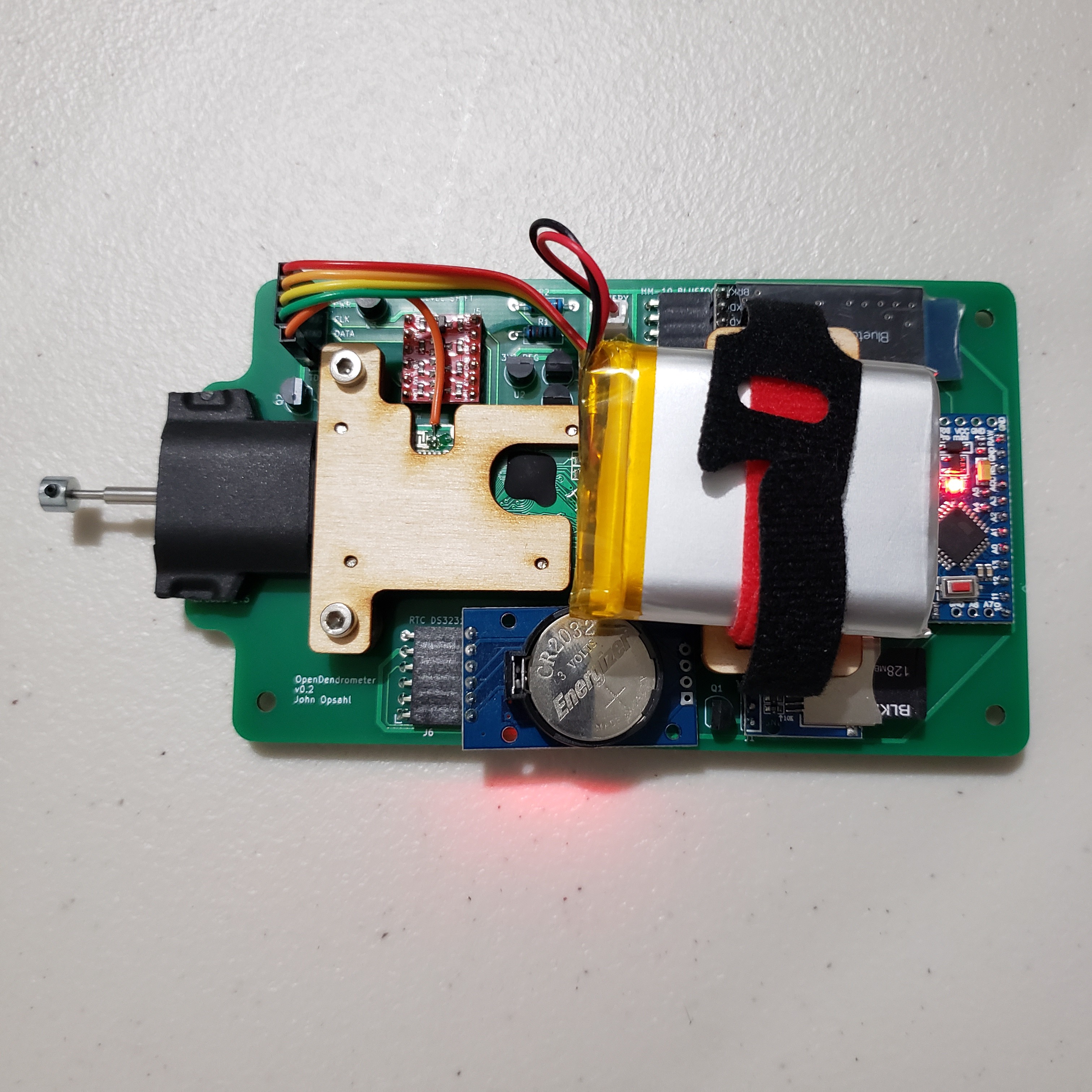
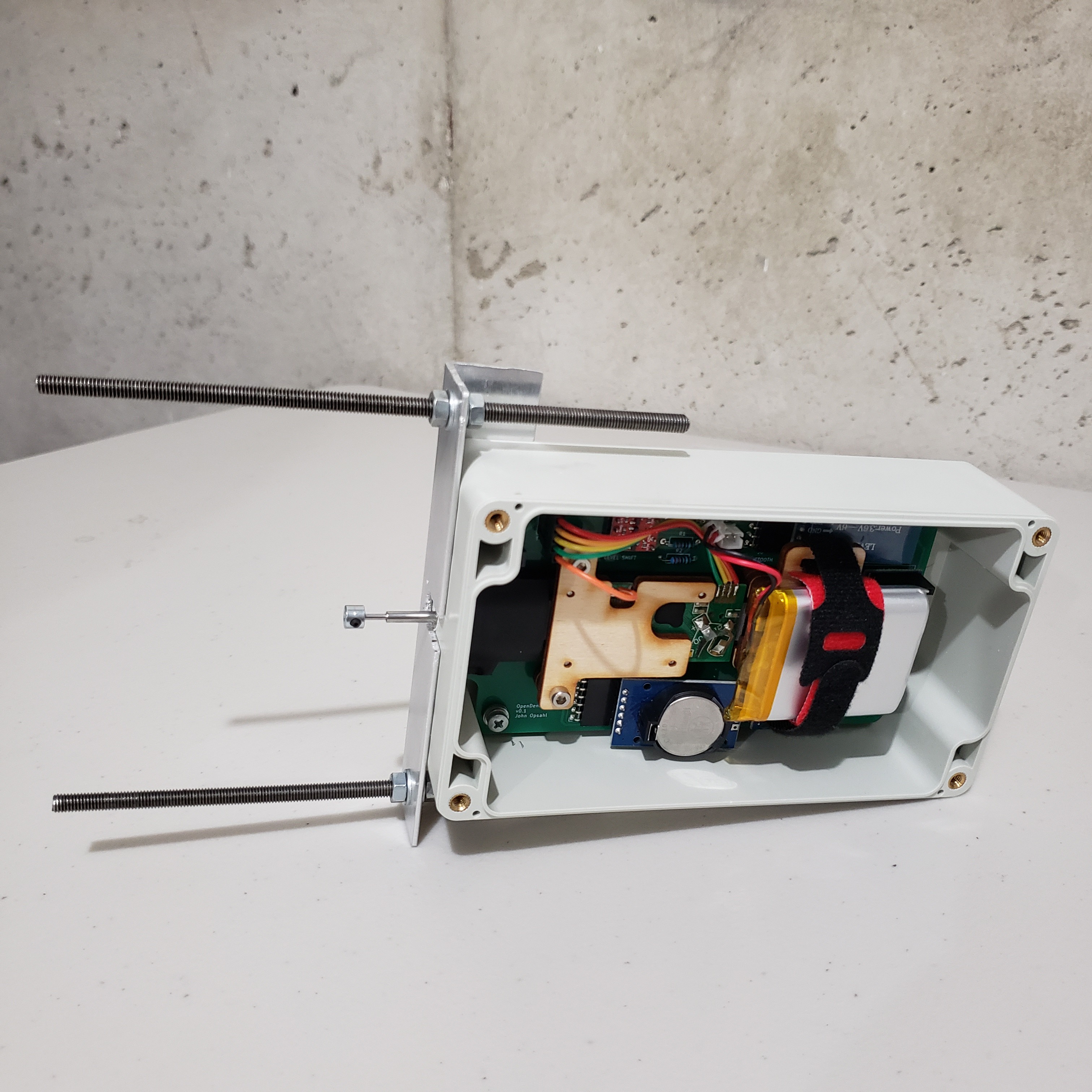
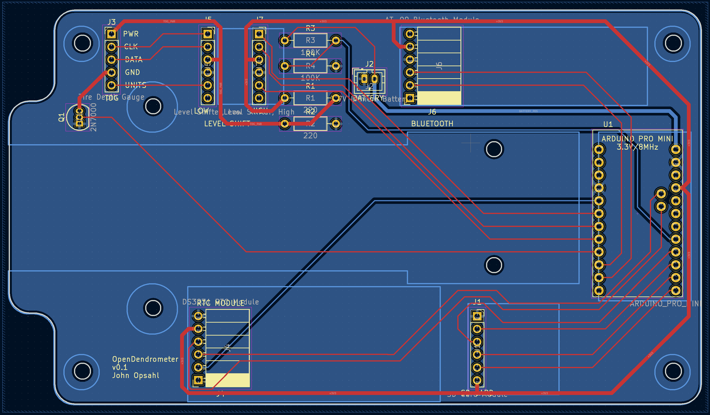
    OpenDendrometer board v0.2 has been received, assembled, and tested. All device functions are working properly. It reads the signal from the tread depth gauge (TDG), logs the TDG measurement and a timestamp from the RTC to the SD card, goes to sleep, wakes up if either the 4 minute period is over or a Bluetooth connection is made, and transfers data over Bluetooth upon request. The only unexpected finding was that the MCP1700-1502E/TO 1.5V regulator is actually providing around 1.3V. to the tread depth gauge. Fortunately, this lower supply voltage doesn't seem to effect the operation of the tread depth gauge. 

    Next step is measure battery current draw during a few test operations. Ultimately, the goal is to confirm that the reduced power consumption strategies are working and to put together a battery life estimate for the device.

    I am super happy with this board revision! Not only has it been my first board revision, but also the first time I haven't fully breadboarded before committing to fabricating the PCB. In addition, I have been wanting to develop a low-cost, low-power, Bluetooth, Arduino data logger design for years now. It is so great to finally see that come to fruition. 

  • Board v0.2 Finalized

    John Opsahl11/20/2022 at 06:01 0 comments

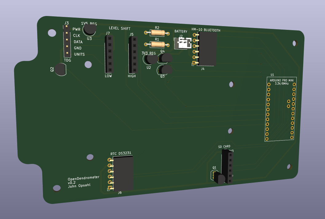
    Version 0.2 of the OpenDendrometer board has been finalized. Boards are out for order with JLCPCB. 

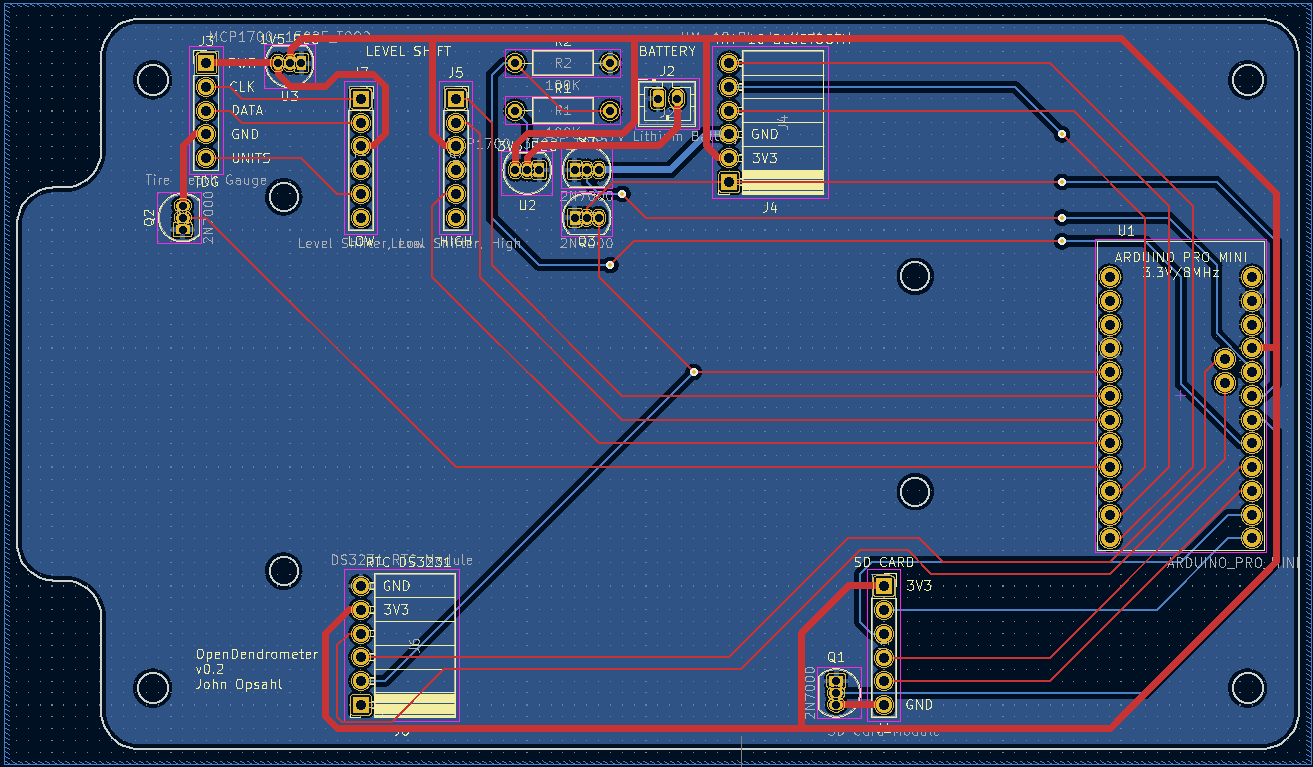
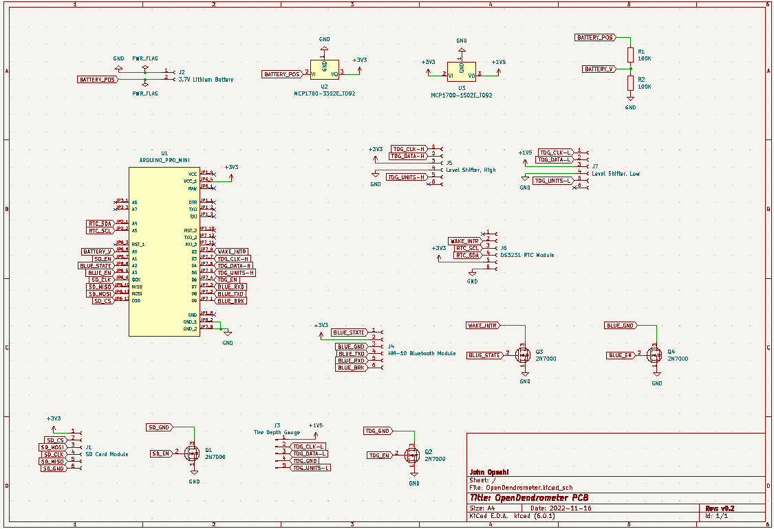
    v0.2 changes include:

    • MCP1700-3302E/TO 3.3V regulator with low quiescent current instead of 3.3V regulator provided on Arduino Pro Mini
    • MCP1700-1502E/TO 1.5V regulator instead of voltage divider off of regulated 3.3V
    • pinout to accommodate the HM-10 Bluetooth module
    • 2N7000 MOSFETs on SD card and HM-10 Bluetooth module power in order to disconnect when not in use to reduce power consumption
    • SD card module flipped over so it is easier to insert the SD card
    • 2N7000 MOSFET on Bluetooth "state" pin for microcontroller wake up interrupt
    • battery JST connector moved closer to the edge for less interference with tire depth gauge wires

    Most of these changes are part of the strategy to more than quadruple the battery life of the device. Interestingly, they will only add about $1.50 to the board cost. Current estimate of time between battery charging with the new strategies is 4 to 6 months.

  • Strategies to Reduce Power Consumption

    John Opsahl11/16/2022 at 04:47 0 comments

    I am planning to use the following strategies to reduce power consumption of the next revision of the OpenDendrometer:

    1. Remove the power status LED limit resistors from the Arduino Pro Mini and the RTC 3231 module.
    2. Use a MCP1700-1502E/TO 1.5V voltage regulator for the digital tire depth gauge power rather than a voltage divider off the regulated 3.3V.
    3. Remove the 3.3V voltage regulator from the Arduino Pro Mini. Use a MCP1700-3302E/TO 3.3V voltage regulator instead. 
    4. Use a 2N7000 mosfet to cut power to the SD card when not in use.
    5. Use a 2N7000 mosfet to cut power to the Bluetooth module during specific hours of the day. 
    6. Log data to the SD card in batches. Fill RTC 3231 4k EEPROM, then dump to SD card.
    7. Put the HM-10 Bluetooth module into a sleep state (via AT+SLEEP command) after disconnect.

  • 2022 Hackaday Prize is Over, Development Continues

    John Opsahl11/10/2022 at 16:17 0 comments

    The big push to achieve a working OpenDendrometer prototype in time for the 2022 Hackaday Prize finals was very successful. Though the project did not secure any top 5 finisher funding through the prize this year, it did receive $500 as a top 50 finalist. Fortunately, $500 goes a long way on this project.  

    I fully intend to use some of that $500 to continue development between now and the end of the year. I have decided on two focus areas for development:

    1. new hardware strategies to reduce power consumption
    2. full implementation of wireless data transfer over Bluetooth

    These changes will require a revision of the OpenDendrometer PCB. 

  • Testing With Bluetooth

    John Opsahl10/31/2022 at 03:30 0 comments

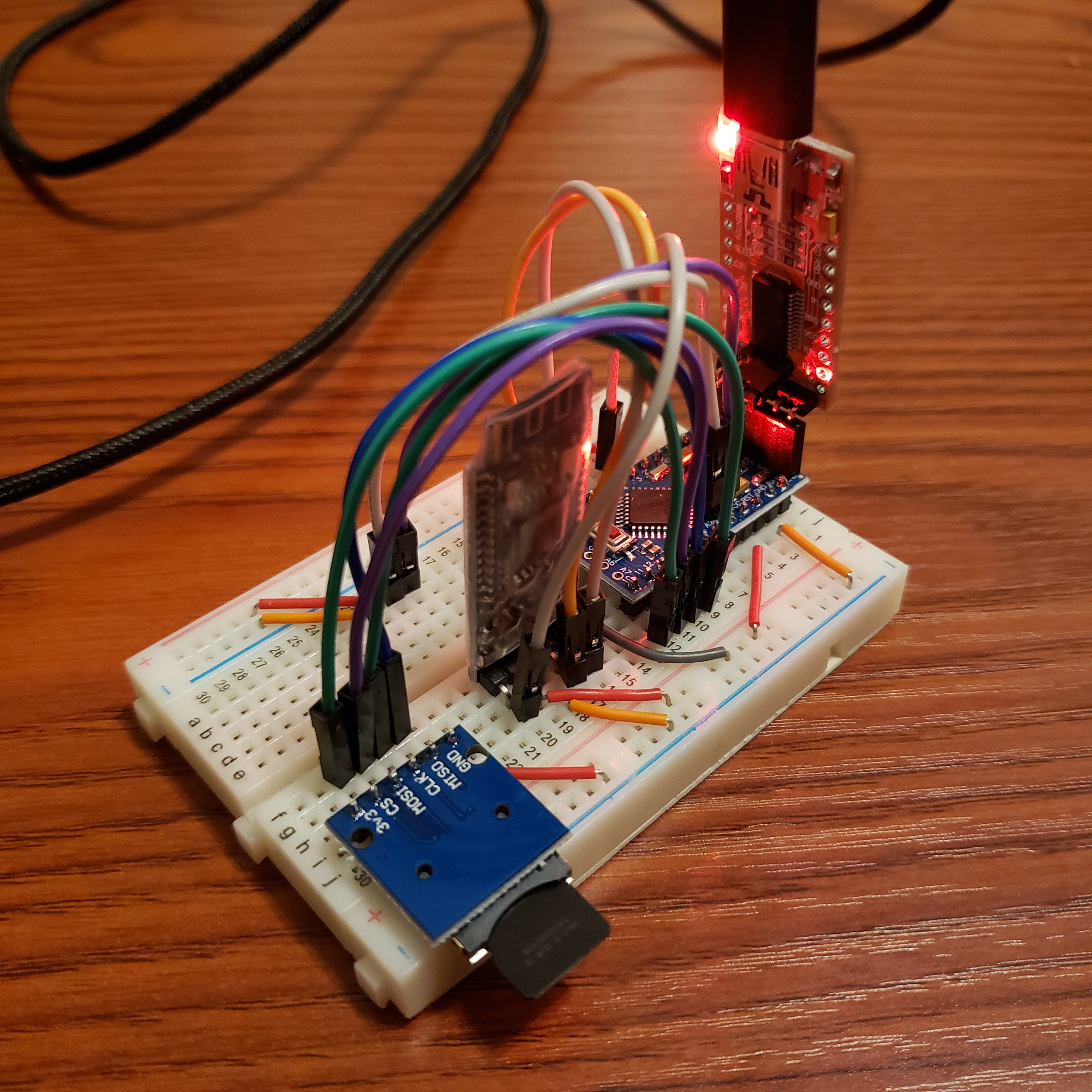
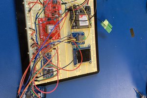
    I was able to make significant progress towards adding wireless data transfer with Bluetooth this weekend. The image above is the breadboard unit used for Bluetooth testing.
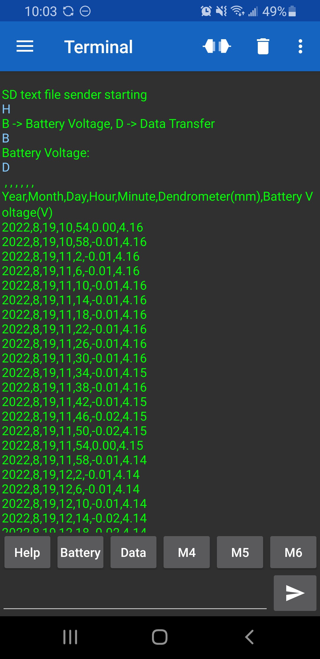
    Earlier in the week I had some issues getting the low-cost AT-09 Bluetooth modules to work. I was unable to connect to them with my phone. They also didn't respond as expected when I tried to configure them with AT commands. Based on comments online, seems like others have had similar issues with the AT-09 modules. To get away from this, I ordered HM-10 modules. The HM-10s have been working great without issue.

    I have been using "Serial Bluetooth Terminal" for Android to connect with the HM-10 on my phone.

    The screenshot below shows some of the functionality is working so far. Blue text "H", "B", and "D" commands are from the phone. Green text is what is received from the Arduino controlled HM-10 Bluetooth module. The "D" command transfers over all data from the SD card to the phone.

    Excited to get Bluetooth functionality added so I can pull data off the OpenDendrometer in the backyard from the comfort of my living room.

  • Unintentional Water Ingress Test

    John Opsahl10/27/2022 at 04:40 0 comments

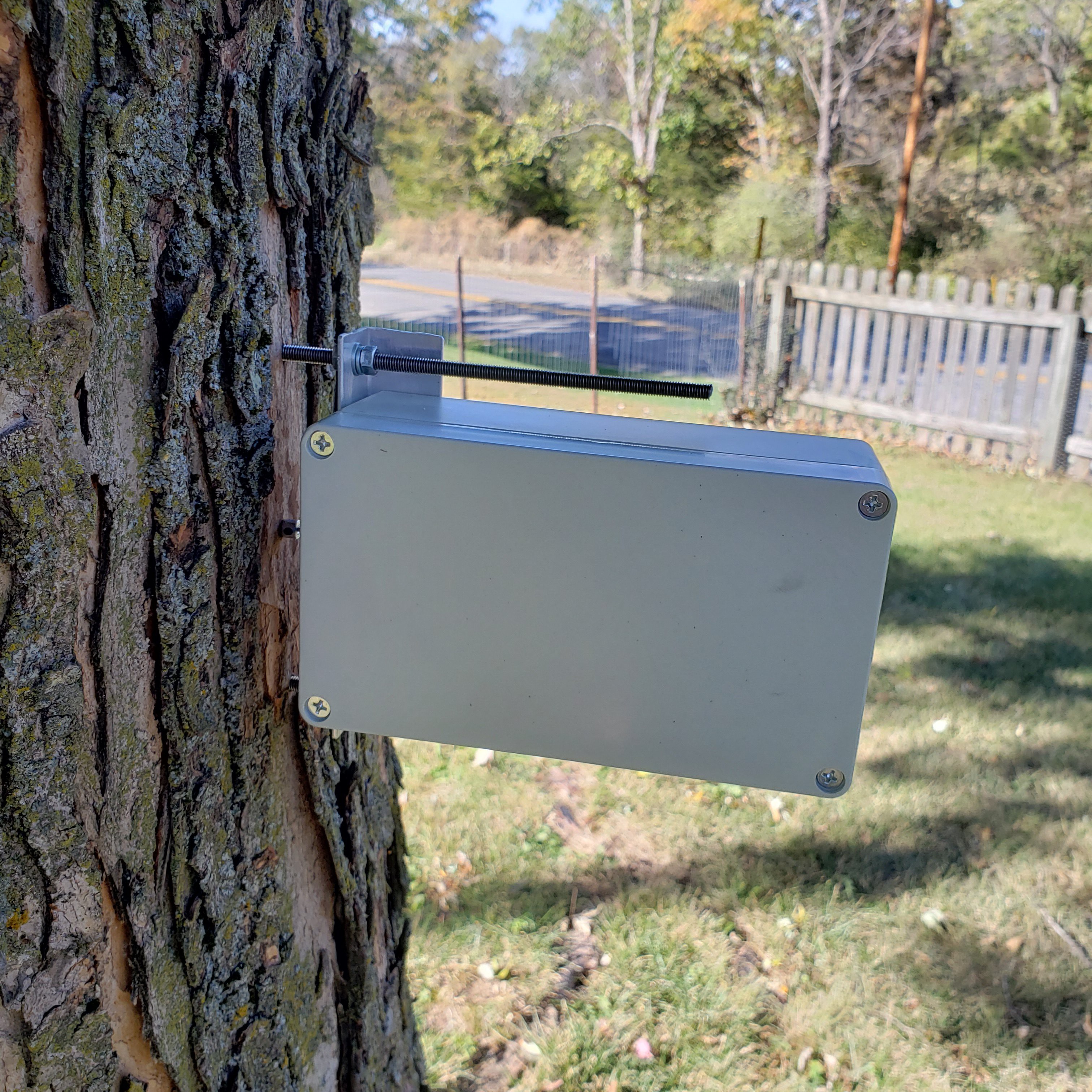
    It happened to start raining during the latest field test. Great to see the OpenDendrometer prototype dry and fully functional after 24 hours of exposure to rain. 

  • The True Power of The OpenDendrometer

    John Opsahl10/23/2022 at 04:08 0 comments

    The true power of the OpenDendrometer is the realization that most of us have so much left to discover and understand about the life of plants. That those seemly unmoving creatures outside your window are actually very dynamic systems and that tools exist to observe their behaviors. 

    It is weird to say since I have spent so much time developing it, but literally all the OpenDendrometer tool does is measure air temperature and small changes is displacement over time. Yet the data continues to capture my imagination about the life of plants -> periods of water stress and abundance, long term growth rates, changes that mark the seasons, and other stories that I haven't discovered yet.

    If my work on the OpenDendrometer has made you even mildly curious about using commonly available electronics components to understand the life of plants, then this project has been a success.

  • First Set of Data From the New Prototype

    John Opsahl10/22/2022 at 01:47 0 comments

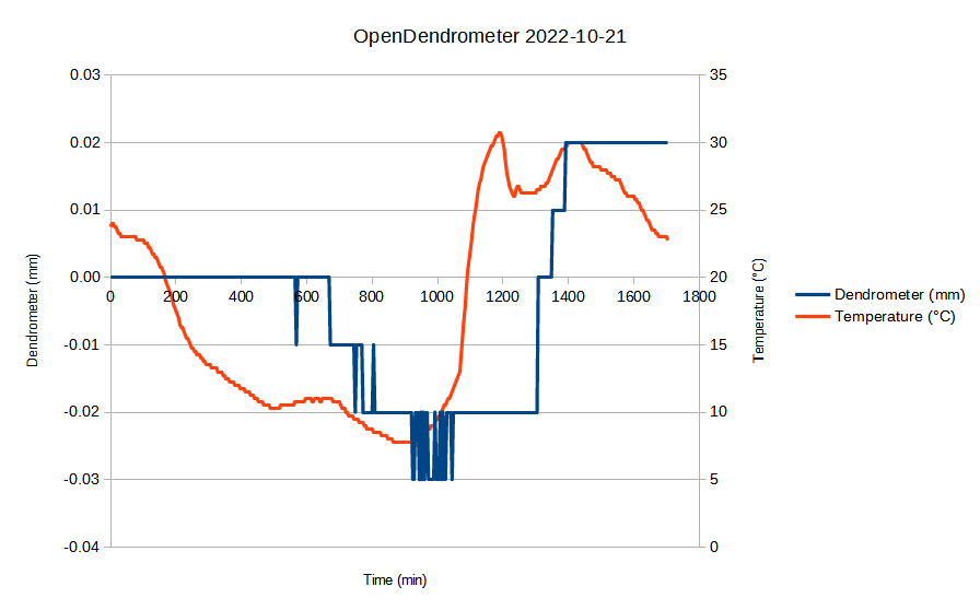
    Great looking data from the OpenDendrometer prototype over the last 28 hours! Showing the expected negative displacement at night (i.e. tree swelling) and positive displacement during the day (i.e. tree contraction). In contrast to the previous OpenDendrometer breadboard development unit, this prototype is showing dendrometer data with much less noise and larger changes in displacement. I suspect the primary cause of these improvements is due to design changes that increased rigidity between the tire depth gauge and the tree.

    It really paid off to start logging the temperature data from the DS3231 RTC module as well. It is interesting to see the response time between air temperature and the dendrometer measurements. 

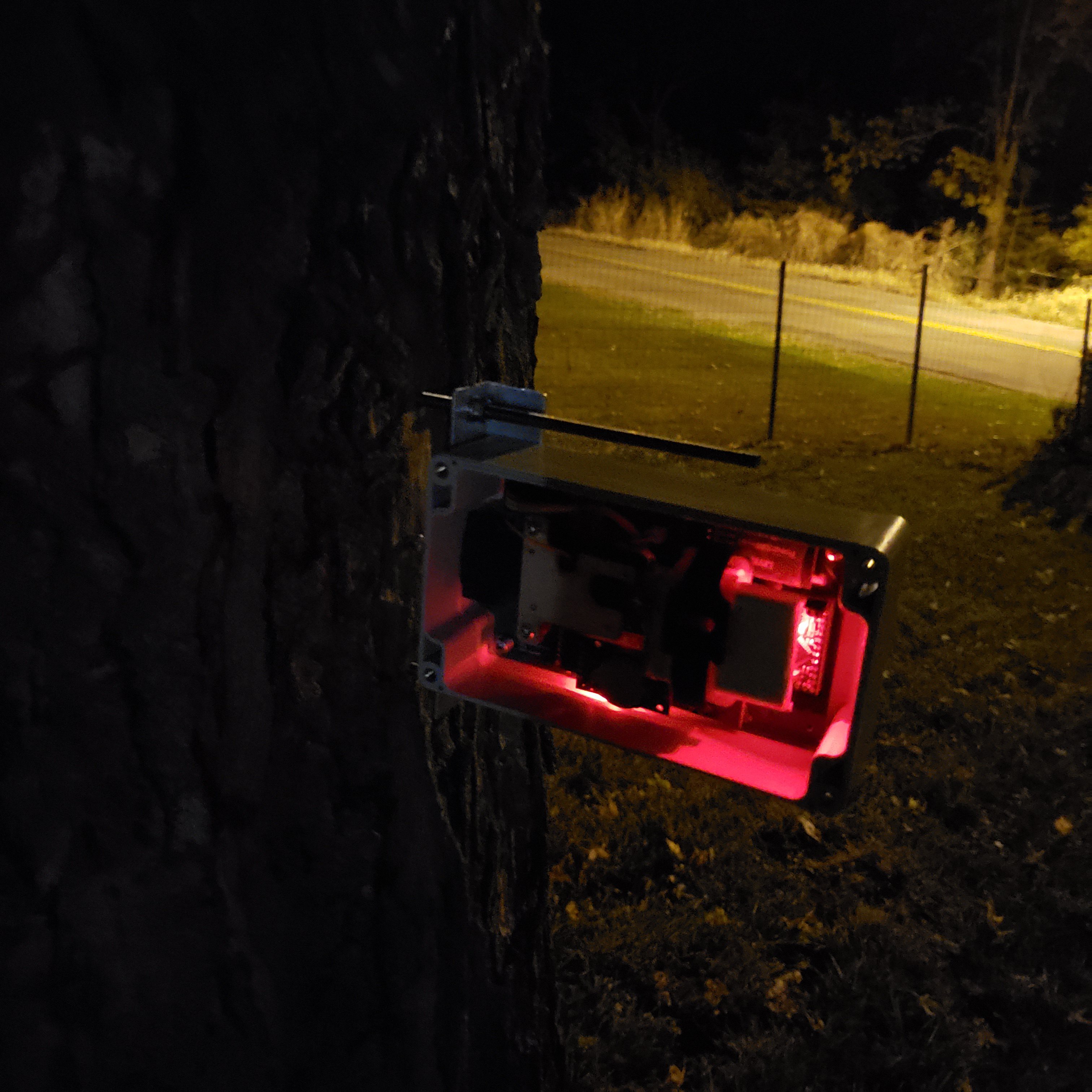
    It was dark outside when I went to collect the data and update the Arduino sketch. A spooky glow from the Arduino and DS3231 power LEDs.

    Next step of the plan is to collect data over a seven day period.

  • Installed and Collecting Data

    John Opsahl10/20/2022 at 20:01 0 comments

    I secured the new OpenDendrometer prototype to the tree in my backyard this afternoon. The plan is to collect data over the next couple of days.

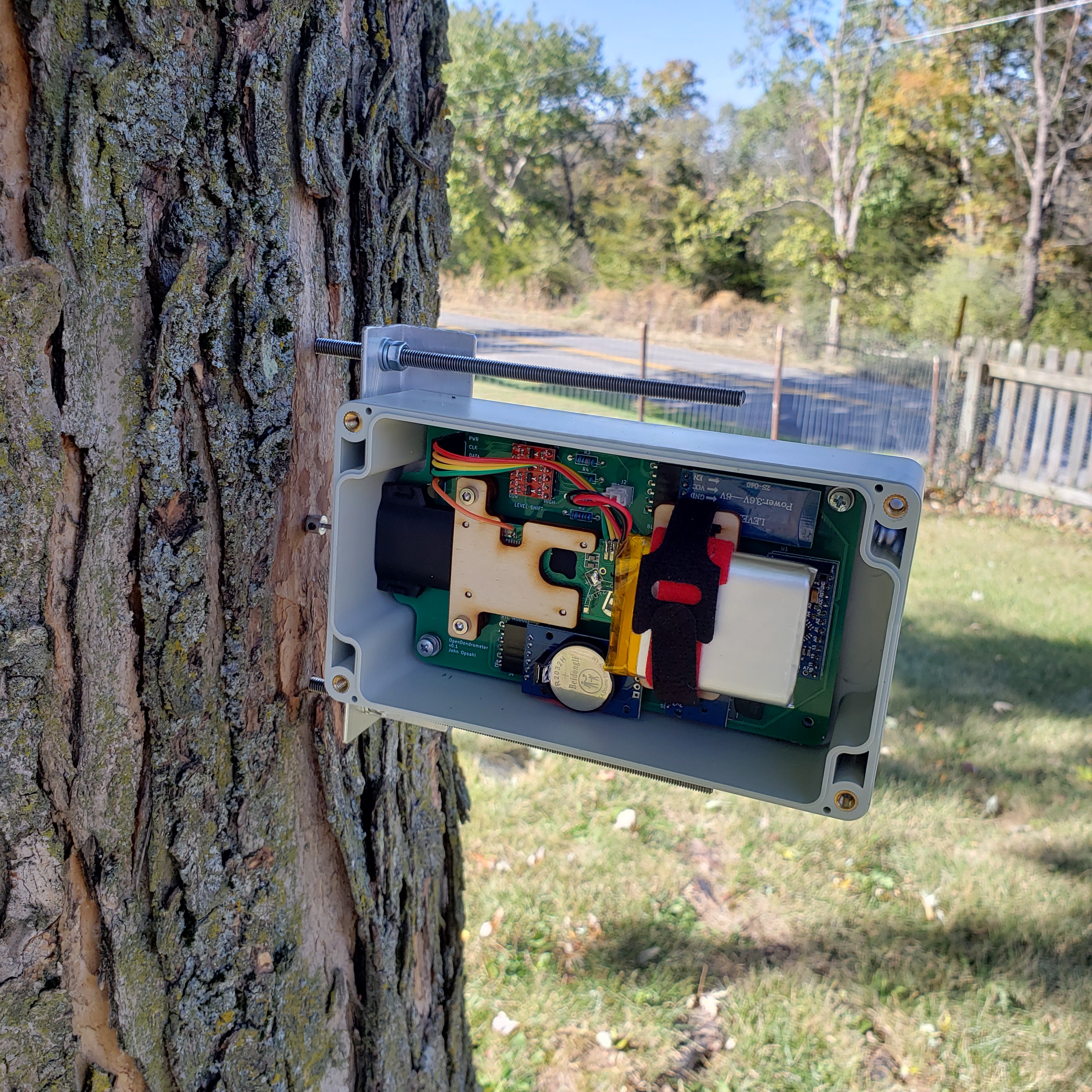
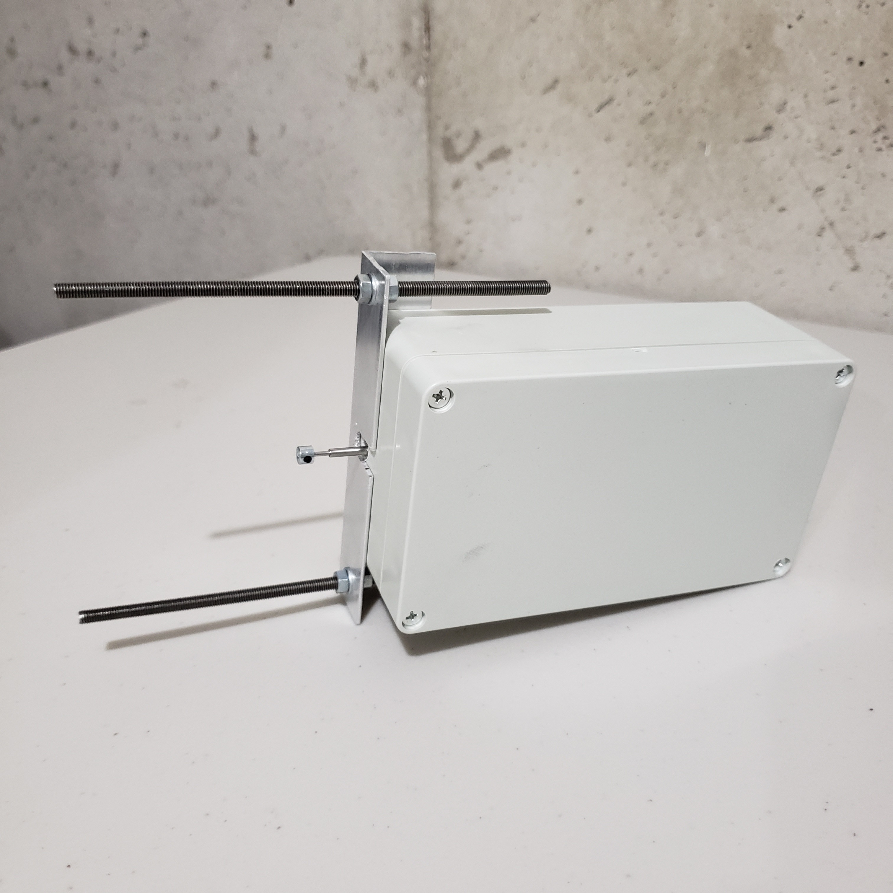
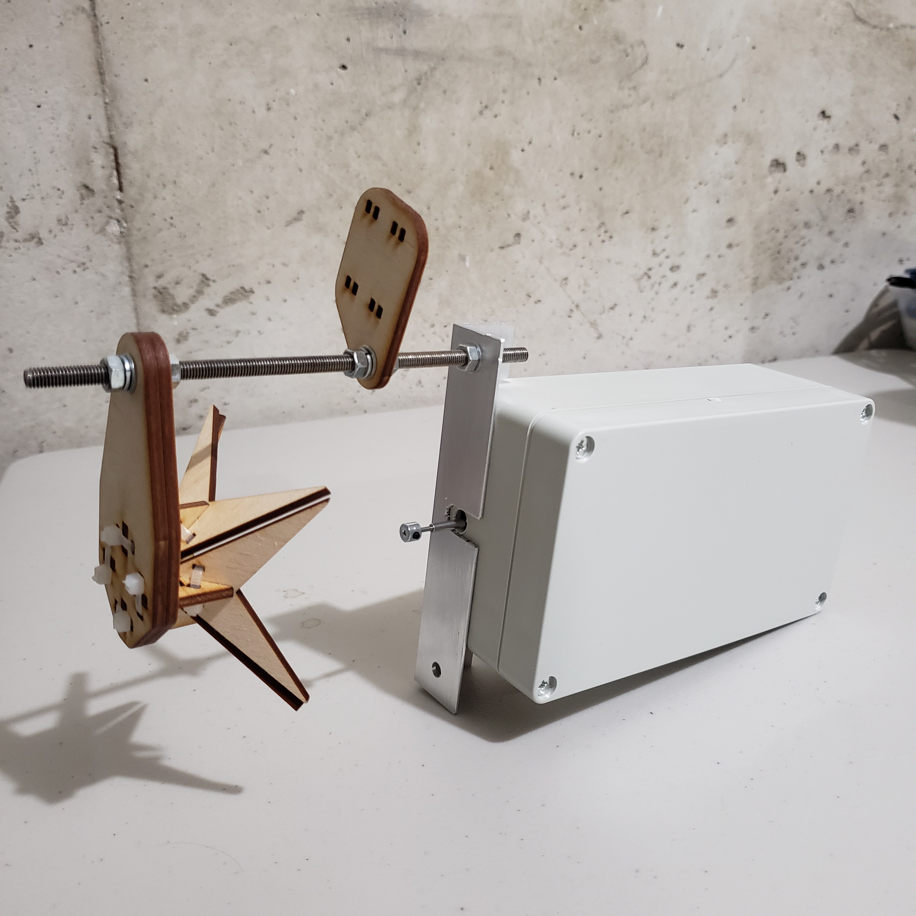
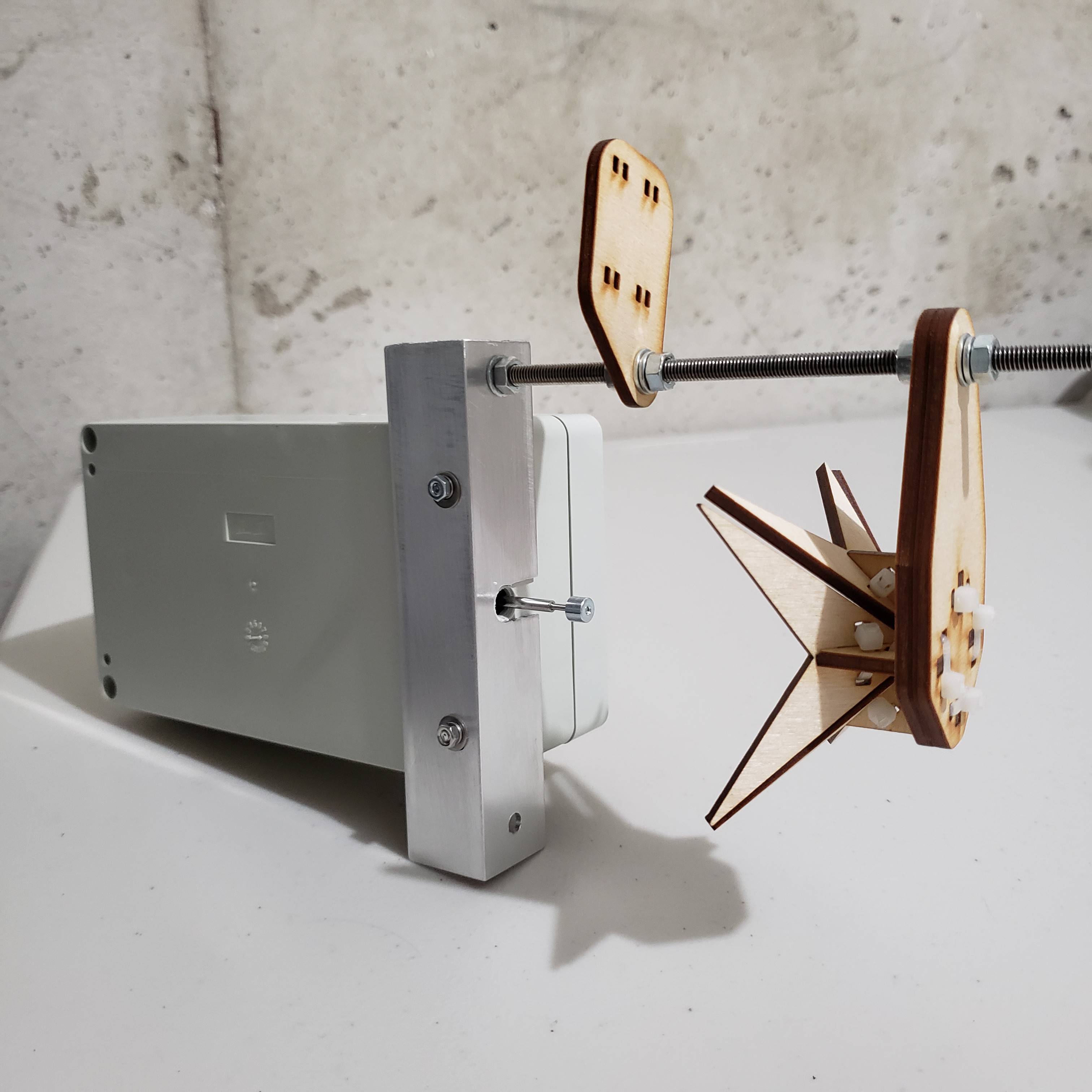
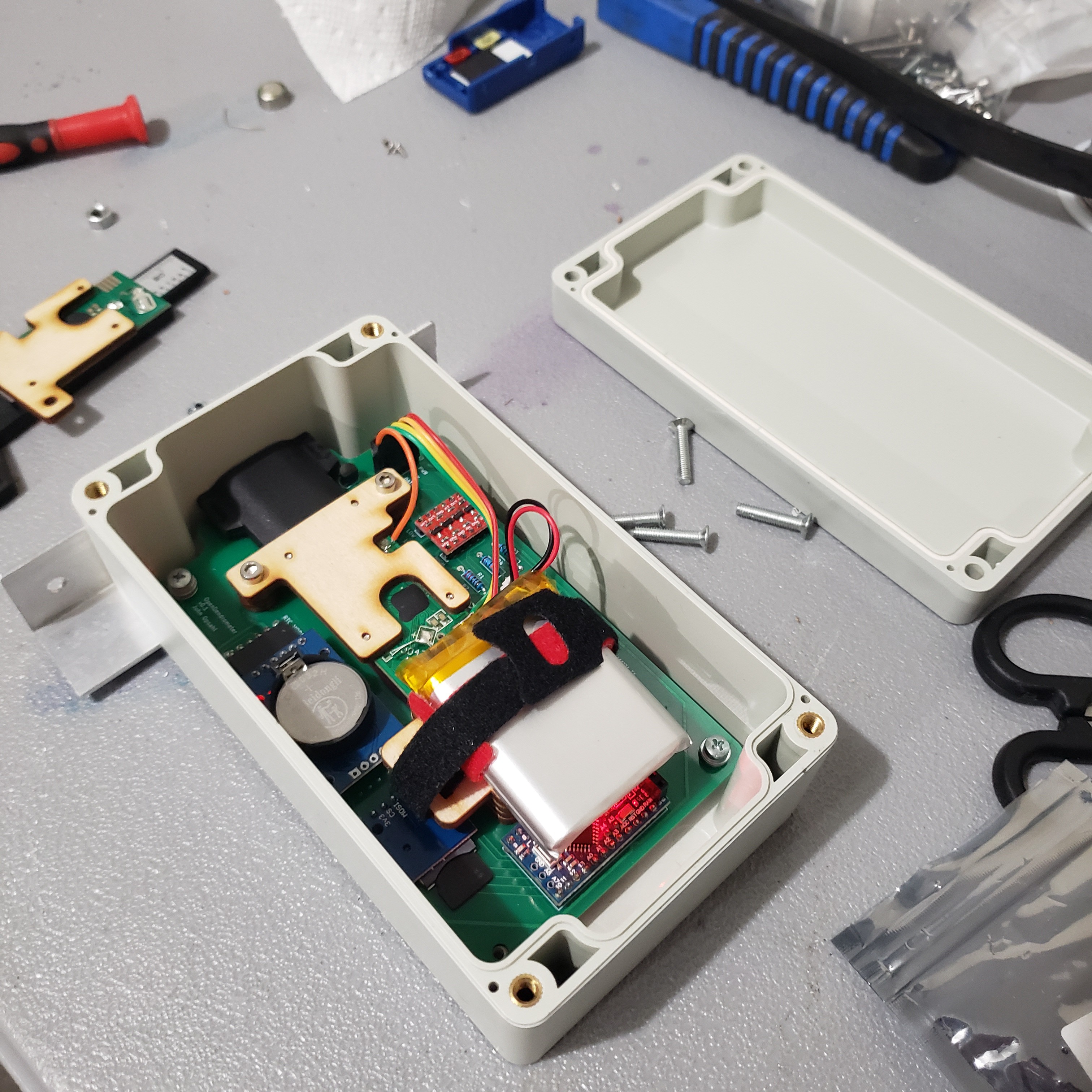
    This new mechanical design includes some features that increase the rigidity between the tire depth gauge and tree. These should improve the device's ability to detect micrometer changes in tree diameter. Changes include: no longer using a 3D printed enclosure (so no material softening at 30°C), two threaded rods to anchor to the tree (previously was only using one), and a metal shaft collar at the probe tip (previously was a 3D printed tip).

    Excited to see the data!

  • Fully Assembled and Ready for Testing

    John Opsahl10/20/2022 at 03:52 0 comments

View all 30 project logs

  • 1
    Purchase Off-The-Shelf Components

    Purchase the off-the-shelf components per the "Components" section of this Hackaday project or the "eBOM" spreadsheet of the OpenDendrometer engineering notebook.

  • 2
    Order the OpenDendrometer PCB

    Order the OpenDendrometer PCB using the latest version of the Gerber and Drill file package located in the "Files" section of this Hackaday project.

  • 3
    Order the Laser Cut Plywood Parts

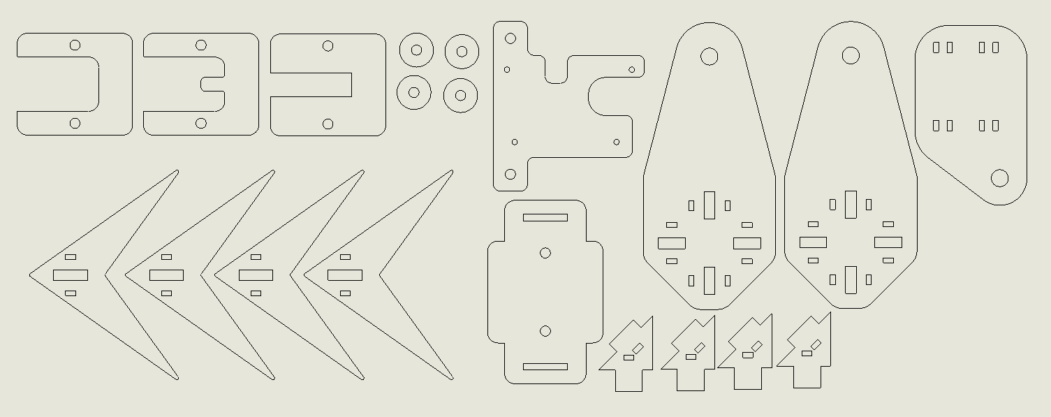
    Order the OpenDendrometer laser cut parts using the latest version of the laser cut DXF file located in the "Files" section of this Hackaday project. Cut from 1/8in baltic birch plywood.

View all 10 instructions

Enjoy this project?

Share

Discussions

Jacob David C Cunningham wrote 08/18/2022 at 14:21 point

haha gotta love the breadboard, ship it!

  Are you sure? yes | no

gregoryaborys wrote 08/04/2022 at 15:53 point

That's amazing. I really want to do this. My electronics skills are poor but it will give me a reason to print more with ASA and TPU. 

  Are you sure? yes | no

John Opsahl wrote 08/04/2022 at 18:04 point

I didn't even know outdoor rated 3D print filaments were a thing. 3D printing an integrated gasket hadn't crossed my mind yet either. Some fun ideas to explore. Thanks for the comment.

  Are you sure? yes | no

gregoryaborys wrote 08/04/2022 at 18:15 point

Thanks for posting your work!  The discount filament company I like just started carrying ASA.  I'd print the TPU separately and use it in to help hang brooms and etc.  Great thing about 3dp is that we can make the container look like whatever we want!

  Are you sure? yes | no

robomaniac wrote 08/04/2022 at 04:34 point

Nice project. Here are comments regarding the "foam cord gasket". I know you are making this a "splash proof" but I suggest you glue the end of the foam cord together with CA glue. Water will get in by there. Remember that the electronic heat up while rain is cold, this will create pressure and water will find it's way in.  Condensation will be the big problem so you can conformal coat all the electronic. 


also a oring compress, so you need to make room for the compression of the oring. In your case it's tight and can't compress well enough. There is lots of documentation and table depending of the oring diameter. Oring are complicated!  I would also place the oring in the cover and not the base that hold the electronic. By doing so, it's easier, faster to print the cover to fine tune the oring compression then the entire base. oh and you technically need more screws to have even pressure of the oring. Will all these tips it will be IP54 :P 
except the hole of the gauge! Grease would help seal.
good luck

  Are you sure? yes | no

John Opsahl wrote 08/04/2022 at 18:34 point

I am a mechanical engineer by education and you definitely hit on my favorite mechanical challenge of this build. 

Great suggestion on gluing the ends of the seal. Hadn't thought about what I was going to do there yet. Gluing is easy.

Once I have a working prototype, I am going to put it outside in the Missouri heat and humidity and see what fails first.

That is a great idea to put the o-ring on the cover. Already need to increase the stiffness of the cover so the additional depth to accept the o-ring has no downsides.

I was planning to have grease at the hole where the gauge goes through. Glad to have a second opinion there.

Thanks for sharing.

  Are you sure? yes | no

robomaniac wrote 08/04/2022 at 18:59 point

I am an electrical engineer and I learn all that from my mechanical engineers coworker. Even the intern was working with o-ring in the shop.
I just finish the design of a lora (helium hotspot) outdoor enclosure. I had the oring thing all wrong in my first version. Then I brought it at work during lunch break and the learning began!  My enclosure is big and what I have inside cost lots of money so I want to make sure it's waterproof. I also think my expectation are high, I wanted IP67 and was dunking the entire enclosure into my pool. LOL Even added a gore vent to equalize pressure.

Then I realize that IP67 is harsh for 3D printing and for my first design. So I now test with 3min under garden hose and try to be IP54. I just want to be rainproof but I do like the challenge to make it the best. I decided to stop messing around and finish the project because it's good enough. Will keep that challenge of been IP67 for a other time.

to increase the stiffness of my cover, I will use carbon fiber. I have a drone design that will get cut by cncmadness and will send the cover at the same time. It's not not big sheet of CF but just a 1cm border where the screws are.  The flex definitively does not help for good seal.

I have lots of trouble to print with ASA so will use PETG while I figure out how to print huge parts in ASA. Anyway lots of fun and most importantly lots of learning.

  Are you sure? yes | no

neilh wrote 08/03/2022 at 18:47 point

Fascinating. Of course the protocol to the sensor looks to be intriguing - I'm assuming its digital. 

I wonder if you've come across enviroDIY.org  they have an Arduino Board (AVR1284) https://www.envirodiy.org/mayfly/hardware/ and software to collect data https://github.com/EnviroDIY/ModularSensors and then a modem Xbee slot, with modem drivers, and then publishers to send to various destinations including https://monitormywatershed.org/.   

I've  am  creating a KiCad board for an extension board https://github.com/EnviroDIY/Mayfly-Modbus-Wing/tree/master/knh002-MayflyWingShield/rev8.  

I'm also in the process of porting the ModularSensors to the Seeed WioTerminal (SAMD51 CortexM4), on https://github.com/neilh10/ModularSensors

  Are you sure? yes | no

John Opsahl wrote 08/04/2022 at 00:19 point

Correct, the signal from the digital tire tread gauge is digital. You can find several tutorials online that detail how to read the digital signal from these with an Arduino. 

I had not heard of enviroDIY.org before. I admire anyone trying to advance the accessibility of environmental sensing in the conservation space. Thanks for sharing. 

  Are you sure? yes | no

Danie Conradie wrote 07/25/2022 at 14:31 point

Interesting project. Does the bar attached to the side of the enclosure in the renderings hooks around the branch or fruit? You could add a temp sensor to check that measurements are isn't getting affected by the enclosure expanding or contracting

  Are you sure? yes | no

John Opsahl wrote 07/25/2022 at 18:39 point

Thanks for your interest Danie! That "bar" is a wood screw. The device is mounted to a tree using the screw. I have some concepts on how to attached this device to a fruit, but the plan is to see if it works on trees first. Good point on the expansion and contraction of the enclosure being a consideration. That is definitely going to come into play on hot days at +/-0.01mm of accuracy. I believe the RTC module I am using for the breadboard unit has a built-in temperature sensor.

  Are you sure? yes | no

Similar Projects

Does this project spark your interest?

Become a member to follow this project and never miss any updates