Joseph Marlin
-
PCB Design, Manufacturing, and Test
02/12/2023 at 20:20 • 0 commentsOver the last three months I have completed most of the 3D printed structural components of the cat feeder, and so I have moved on to the brains of the operation.
The requirements for this project, as I assigned to myself back when I first started are:
- Aesthetically pleasing
- Secure - not vulnerable to my cats robbing it anytime they want a snack
- Configurable remotely via network (Wifi)
- Solid construction
- Ease of maintenance
- Low food warning
- Food capacity for two weeks or more
- Painless food refilling process
- High reliability
With these requirements in mind, I set off to design the circuit board that will control the cat feeder. I knew right off the bat that I would be using the ESP8266 based Wemos D1 Mini, because I've used them before and they are perfect for this - WiFi connection, small form factor, and sufficient IO for the project.
Besides that, the other interfaces that would be needed are:
- Ultrasonic distance sensor
- To sense when we're running out of food
- Addressable LEDs
- To make the crystal glow all pretty
- Motor control
- To move the cat feeder wheel.
Next, I set off to gather some parts. Here are the ones I selected:
- Ultrasonic distance sensor: HC-SR04
- Motor: Uxcell Dual Shaft 10RPM Wormgear Motor
- LEDs: WS2812B White, 5 meters 30 LEDs/meter, IP65, LED light strip
- Power Supply: 10A 5V Power supply
- Wemos D1 Mini
After gathering these materials, I began the board design. I chose to start with 5V and use a boost converter to supply 12V to the motor. Although power motors with a boost converter can be tricky, I felt that making a 10A power supply to supply the hungry hungry LED strip would be more trouble than it was worth. The LEDs 1.8A per meter at full brightness white. Although I expect to operate them neither at full brightness, nor full duty cycle, nor always white, it nevertheless seemed more appealing to me to start with 5V and boost to 12V for the motor.
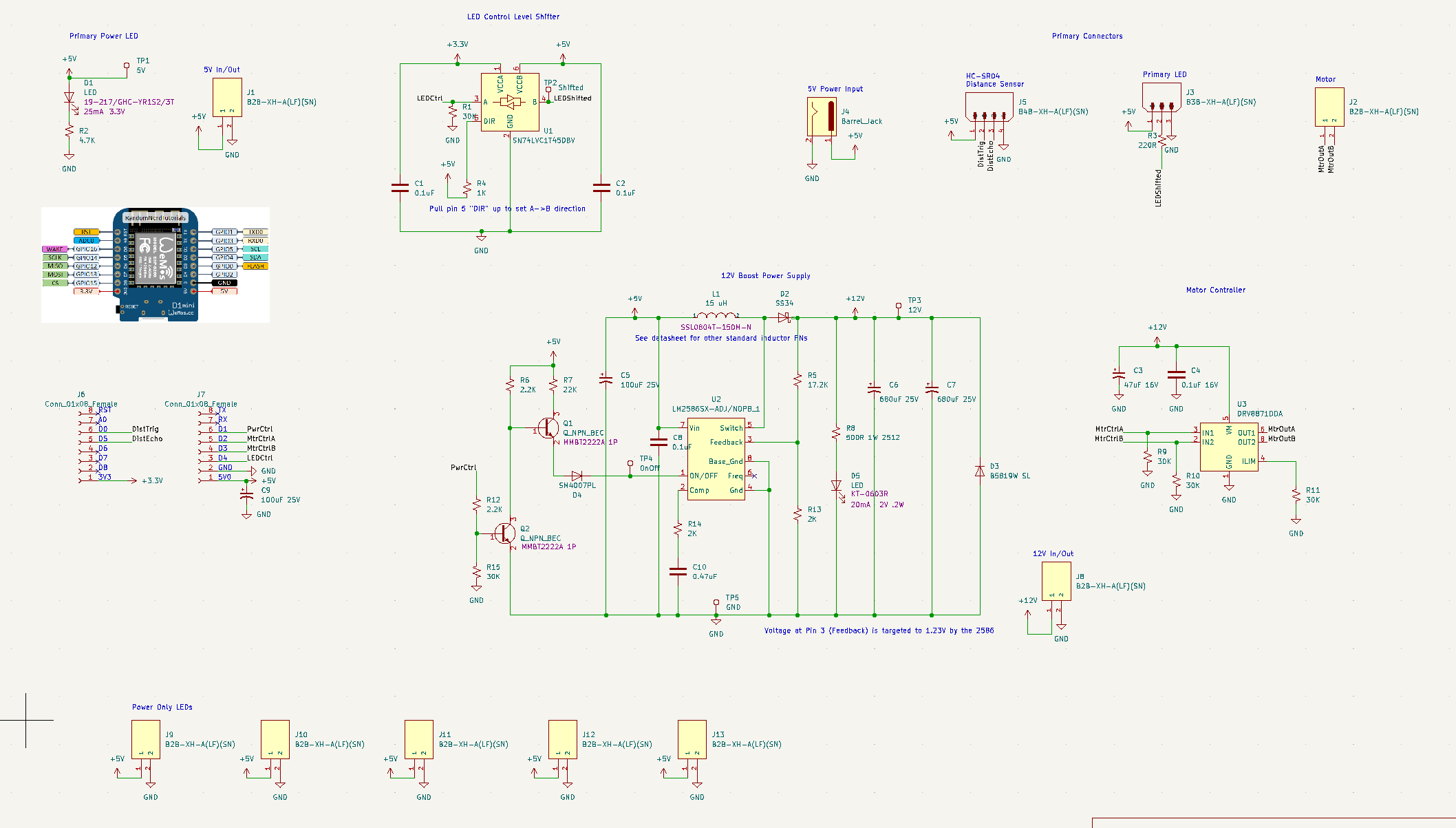
Here's what I developed:![]()
Multiple 5V power supply ports are available in order to power the LEDs - the control line can be daisy chained and each segment can have its own power port, keeping the current on the wires limited. I'm unsure if I'll be using that feature though.
I also included a level shifter - the 8266 uses 3.3V logic, and although that could work with just a few LEDs, the long strand of WS2812B programmable LEDs I am baselining made me want to supply a 5V signal.
Next we have the LM-2586-ADJ. This is the adjustable version, that required a specific ratio between R5 and R13 to ensure the output was 12V. There is a 12V specific version, but my board manufacturer, JLCPCB, didn't have it in stock.
You might also be confused by the weird looking double-BJT. This is because Pin 1 is dual use. It is the on/off pin, and it is also a frequency adjustment pin. You can either pull the pin high to shut down the chip, or leave floating to enable the chip. If you pull it down, the frequency adjustment mode gets activated. Thus, the double BJT scheme provides both an inverter from the ESP8266 control signal, and ensures it is floating, not pulled down, when the chip should be active.
Lastly, I put in a DRV8871DDA H-bridge controller ship. Although I don't need to turn the motor both ways, this gives me the capability should I decide I want it. It also just provides an easy way to turn the motor on and off besides simply killing the power supply.
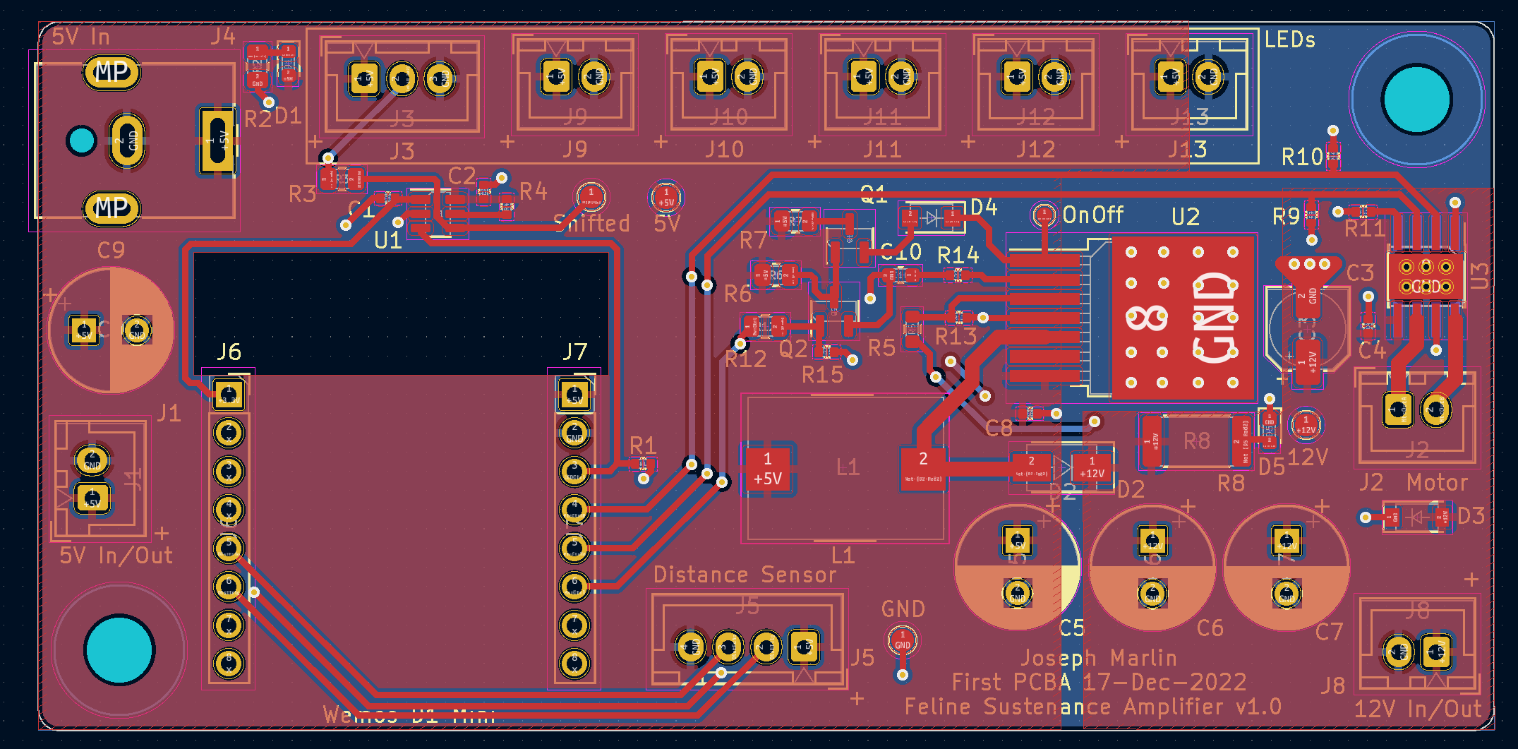
Next came layout, which ended up being fairly straightforward.
![]()
I used KiCAD for this, and the tool is fairly easy to use. The 5V side of the board is on the left, the LED ports on the top. The 12V regulator is center and H-bridge is far right. I also provided 5V and 12V access, at the recommendation of an engineer I found on Fiverr who reviewed my PCB for me. This allowed me to both supply and source these voltages externally should it be needed some day.
I put a lot of capacitance on the 12V side to supply the inrush for the motor, and was surprised to see that there is no good way to calculate how much capacitance you might need. My Fiverr reviewer was also concerned that the power draw from the motor might drop the 5V supply enough to cause the ESP8266 to reset, so I added more capacitance on that side too.
![]()
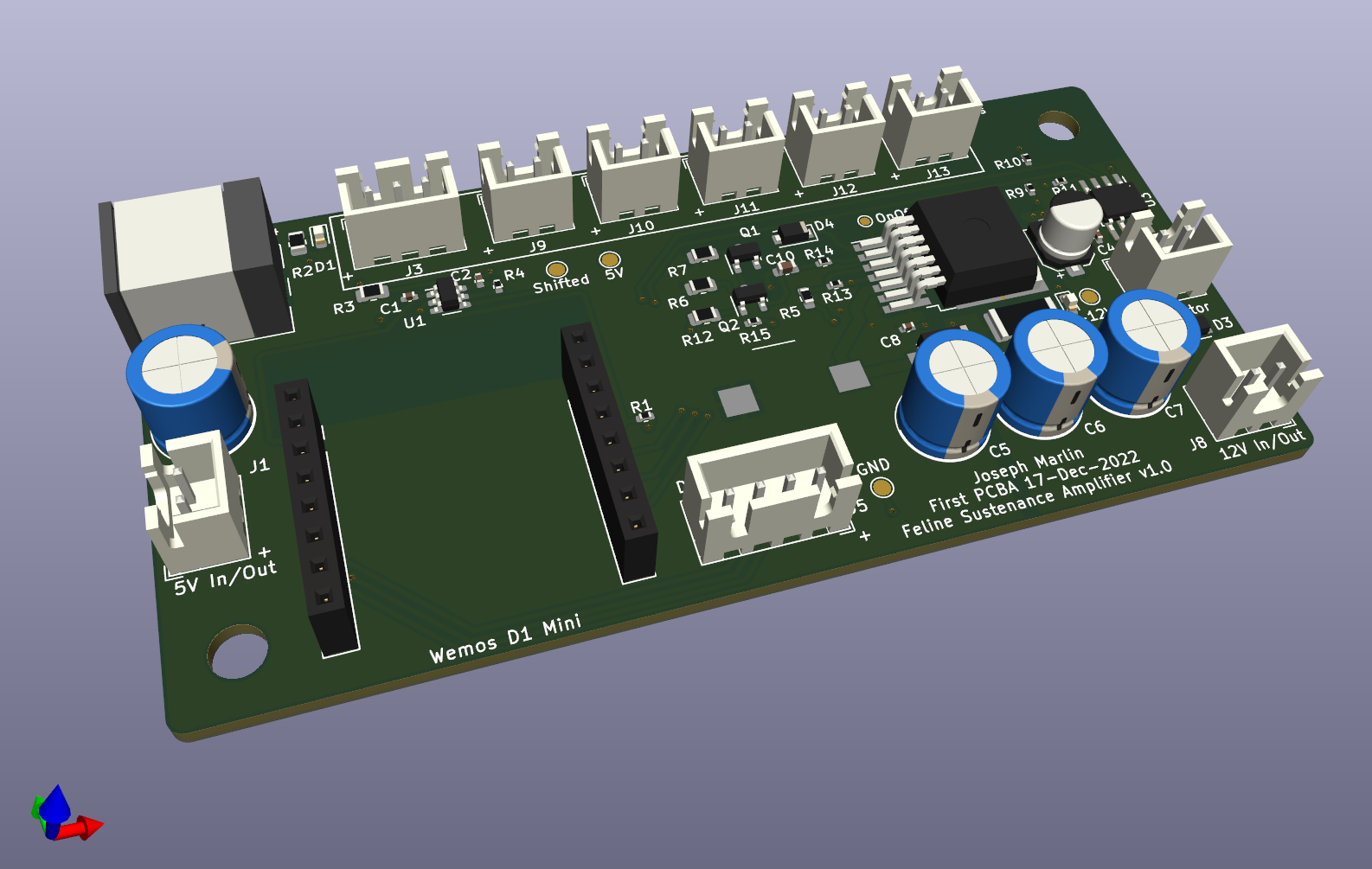
Finally, designed and ready to build, I headed over to JLCPCB. I opted to have two assembled, which I envision using as a "dev unit" and a "production unit". One to hack around on and figure out the problems, and one to use on the actual cat feeder.
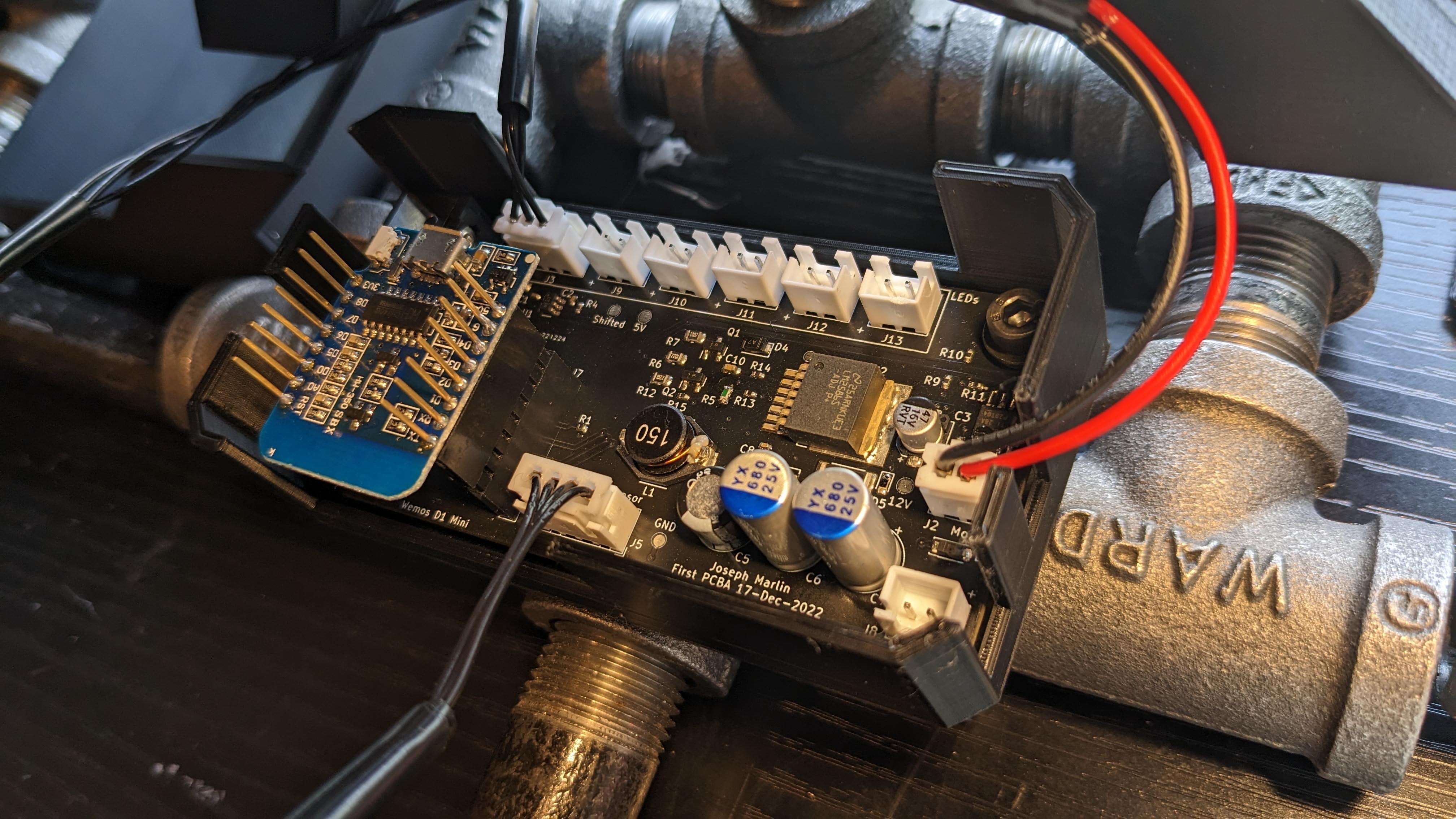
Finally, the big day arrived, and I received the boards.
![]()
I carefully began turning on the circuits, one at a time, and I am thrilled to say it substantially works right out of the box. Of course, no PCB is perfect on the first try - here are the issues I found:
- 5V is present on the 12V rail all the time 12V is not enabled.
- The only down side of this is that the 12V indicator LED is on all the time.
- 12V ends up being 11.75V, pretty good, probably due to tolerance in R5 and R13
- I reversed the pinout of the ESP8266 so it is backwards. This makes the USB hard to access while mounted, but otherwise is ok.
- Case did not fit because
- the caps are taller than expected/modeled
- the now-reversed 8266 extends past board outline.
- 12V LED is wildly bright
- D3 diode let out magic smoke when 12V enabled for the first time - symbol is backwards in KiCAD.
- Haven't replaced it and have not seen any ill-effects from flyback yet.
None of these issues blocked progress though, so I've been continuing to work on the code that will operate the actual cat feeder, which I will share as the next log. The distance sensor works marvelously. The motor turns smoothly and exhibits no issues. The LEDs light and are controllable with no issues. I am not currently using any of the extra power ports, but I also used relatively small wire, so I may have to eventually.
-
On Pausing Prints
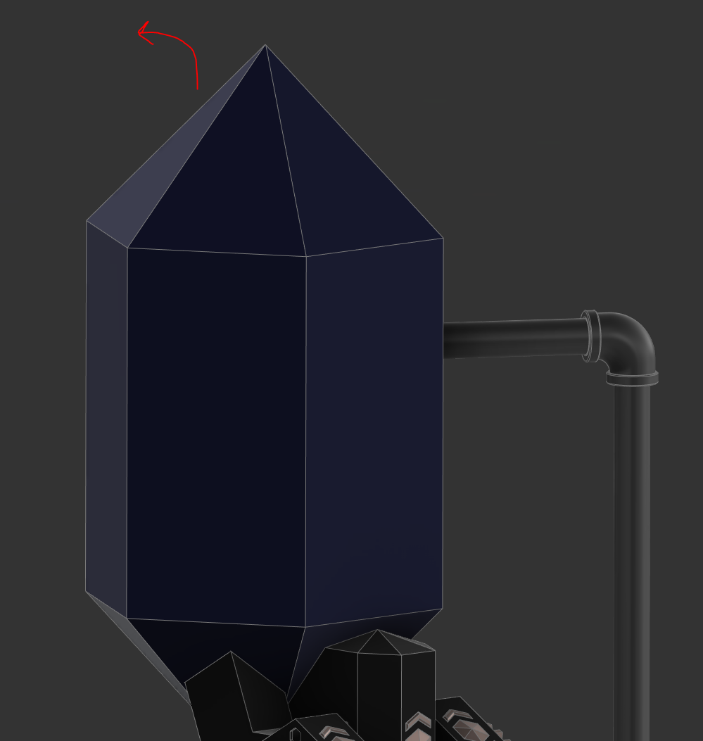
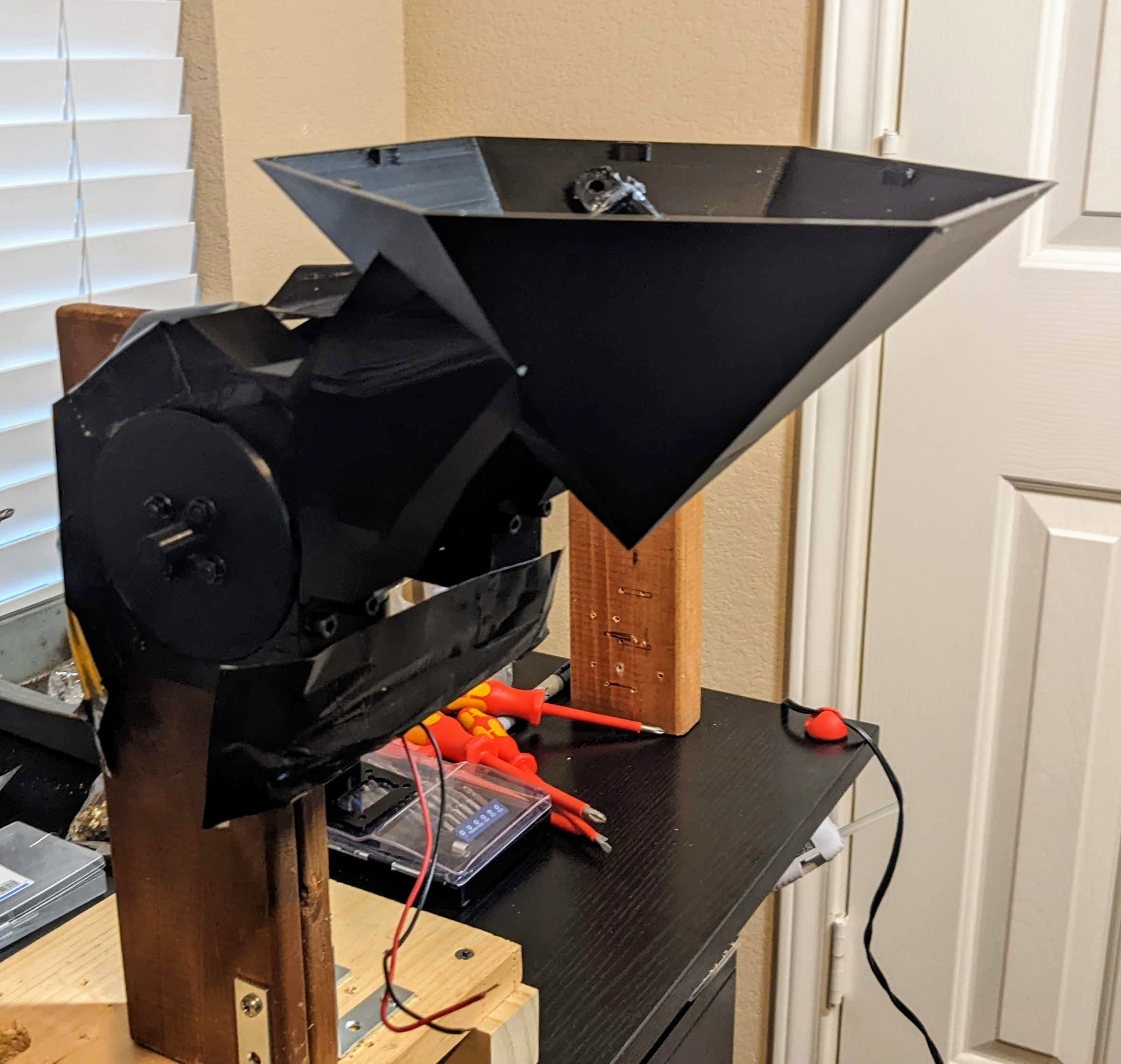
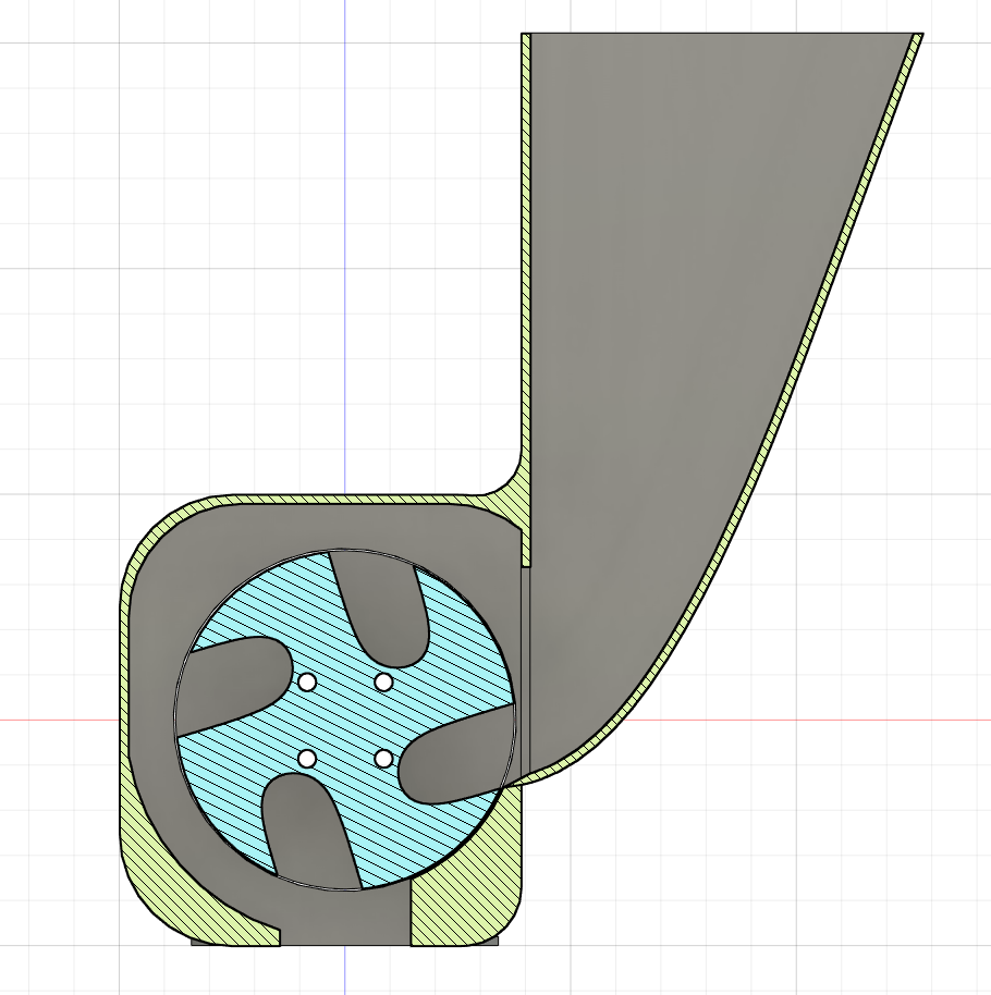
11/12/2022 at 18:08 • 0 commentsMy cats are little buggers, so I need to ensure that this cat feeder is secure. There is a big opening at the top of the hopper where food is added, and that is a big giant vulnerable area for hungry cats to attack. Illustrated below is what I mean by this - the diamond shaped top of the hopper opens up on a hinge to allow food to be added to the hopper.
![]()
I am looking to avoid big ugly locking mechanisms though, so I thought I would try adding embedded magnetics into the build. This was my first time attempting to add something to a print mid-build.
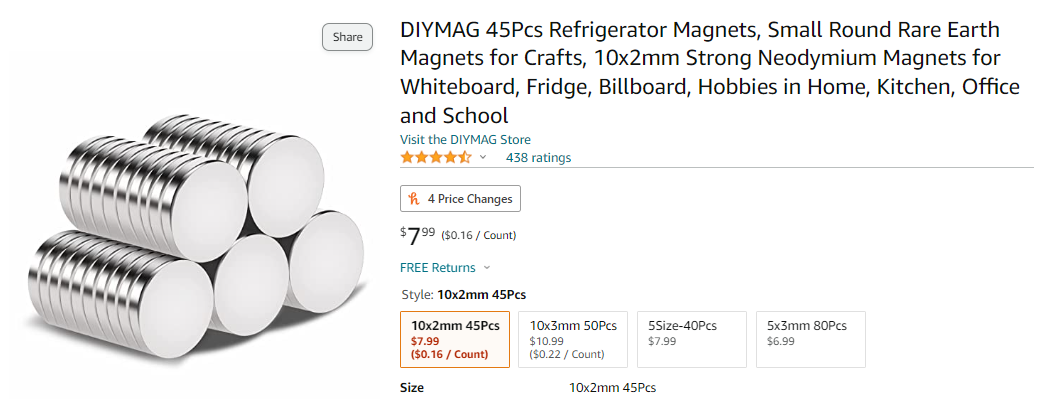
So, I bought these small button magnets from Amazon.
![]()
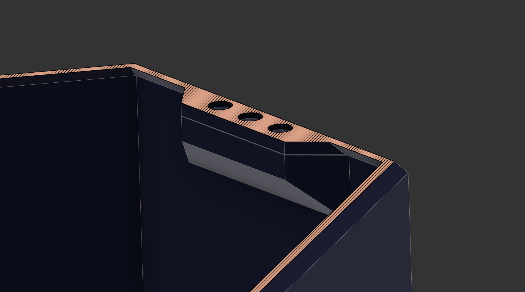
They seemed quite strong, so I decided to arbitrarily start with three and experiment to see if more were needed. I made little pockets for them in the interface where the lid of the enclosure. I added three to the lid and three to the hopper base. Below are illustrated the three pockets in the hopper lid.
![]()
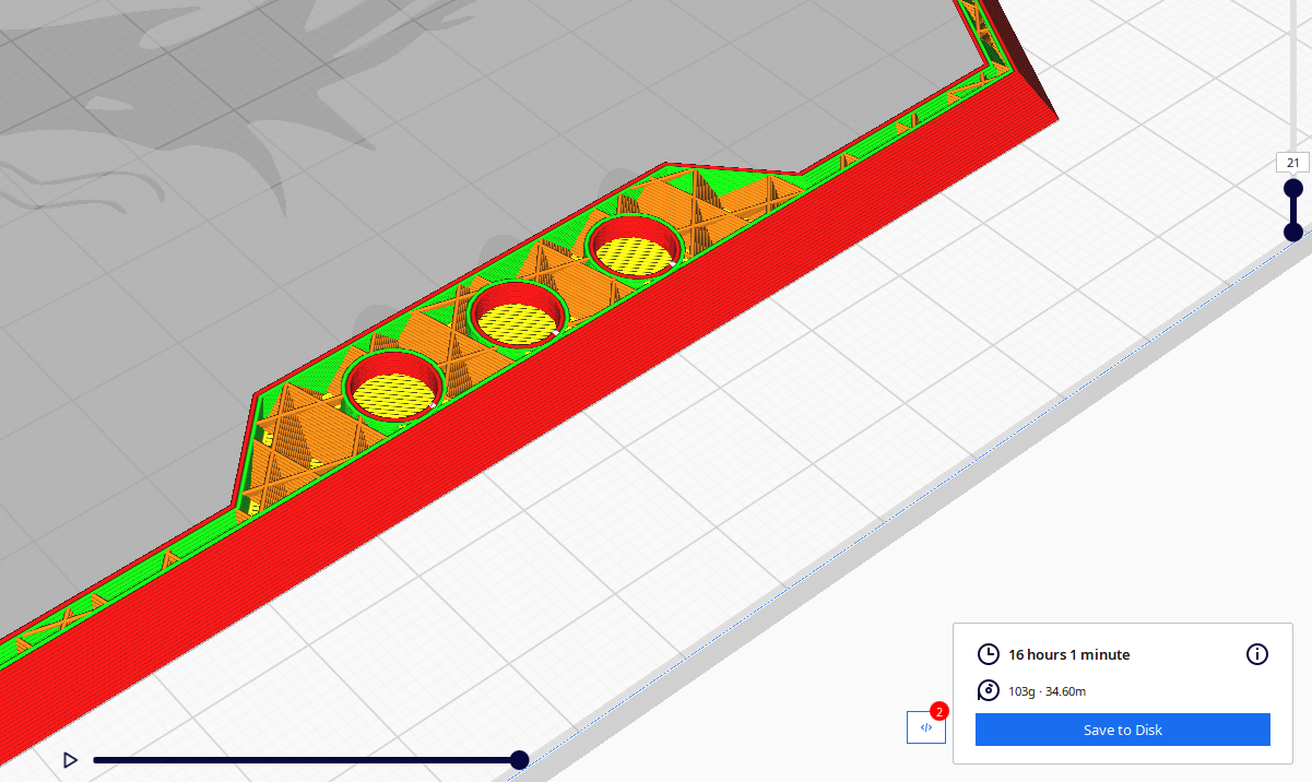
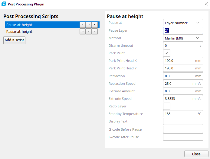
Next, I printed a test. I sliced in Cura and added a pause at the layer just before the pockets get covered up and embedded.
![]()
![]()
This means that after layer 21, the print will pause using the "M0" gcode command (which OctoPi will actually intercept and use its own built-in pause feature), and then when the magnets have been inserted into the pockets, you may can resume the print.
There was a critical issue with this. Upon trying it the first time, I found that I was unable to insert the magnets without accidentally bumping the print bed. This meant that while the magnets were successfully installed, resuming the print resulted in an offset print, and it failed.
After some research I was not able to come up with straightforward way of locking the steppers. I did see someone online recommend attempting to simply move the bed slowly back and forth while working on it. This would keep the steppers engaged and ensure that some very slight force from my hands would not shift the bed.
I executed this with the below gcode:
M83 ; switch to relative E values for any needed retraction
G1 F300 Z5.2 ; move up a millimeter to get out of the way
G1 F9000 X190 Y190
G1 F300 Z15 ; too close to bed--move to at least 15mm
M104 S185 ; standby temperature
M0 ; Do the actual pause
G91
G0 Y-60 F60
G0 Y60 F60
G0 Y-60 F60
G0 Y60 F60
G0 Y-60 F60
G0 Y60 F60
G0 Y-60 F60
G0 Y60 F60
G0 Y-60 F60
G0 Y60 F60
G90
M109 S185 ; resume temperature
G1 F300 Z4.2
G1 F9000 X26.843 Y73.019
G1 F300 Z4.2 ; move back down to resume height
G1 F1500 ; restore extrusion feedrate
M82 ; switch back to absolute E values
G92 E2748.70151
;LAYER:20
After the "M0" pause command, I then resumed the print, and the bed began slowly moving back and forth for about five minutes. I tried this and it worked like a charm, allowing me to install the magnets and then resume the print, resulting in them being embedded in the print.
The other issue was that due to the high strength-mass ratio of these magnets, they kept jumping out of their pockets to stick to each other before they could get encased. (At least they didn't stick to the nozzle!)
This was easily fixed with a tiny bit of super glue when inserting into the pocket.
Finally, both the top and bottom were printed - time to test the magnets.
Sadly, the result was extremely disappointing. Due to the 0.4mm of distance between the magnets (0.2mm) for each side, the magnetic force attracting the lid to the hopper was almost undetectable. I estimate it required only about a quarter pound of force to separate the lid from the hopper.
My cats let nothing stand between them and food, so this simply will not do.
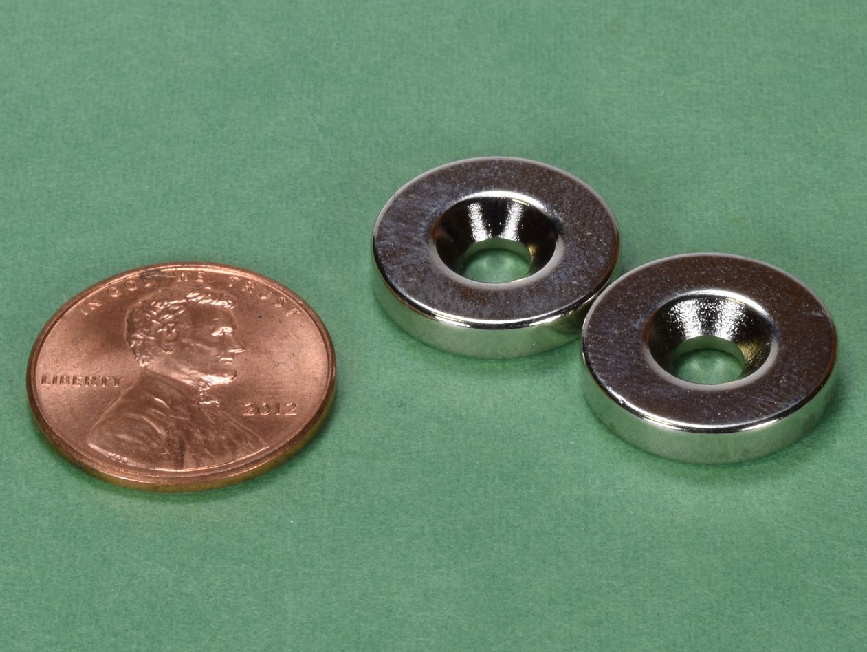
Thankfully, I met someone at this years Hackaday Supercon who recommended I check out K+J Magnetics, which sells magnetic rings with a hole for a flat-head countersink screw.
I purchased two pairs of RA22CS-P-N52. Thanks to the countersinking ability, these should be way easier to install too, not requiring any print pausing!
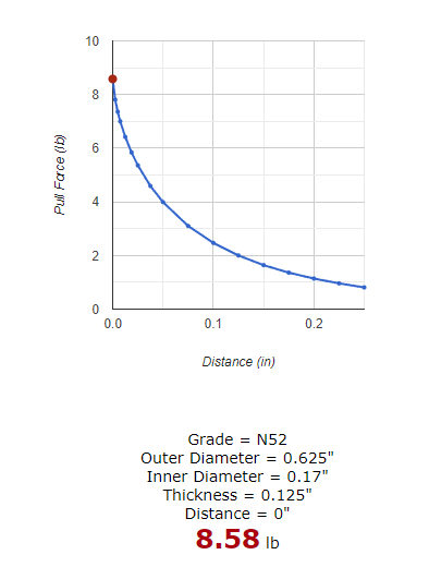
![]()
According to their excellent data, should each provide over eight pounds for force against opening the hopper. Combined, that is 17lbs of force, which I'm cautiously optimistic is more than my cats can bench.
![]()
I'll report back when I receive the magnets, redesign the interface, and test the force.
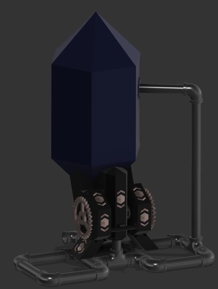
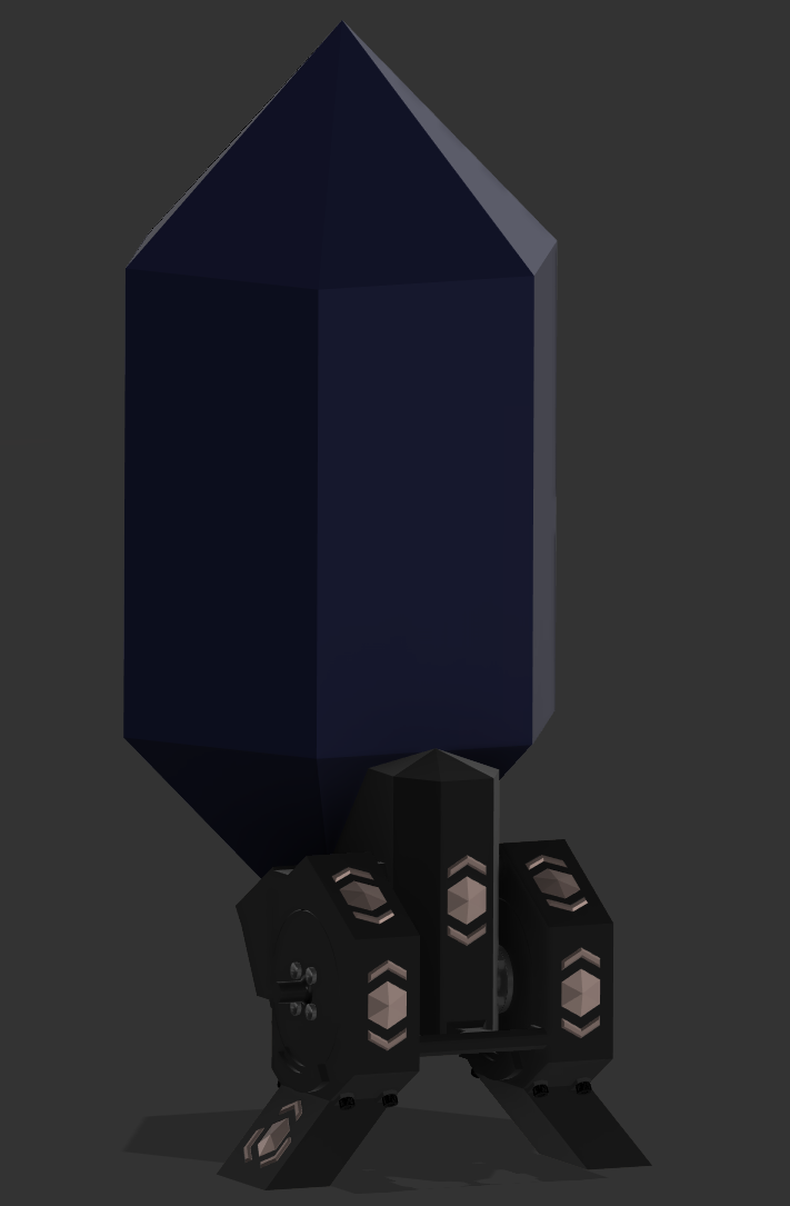
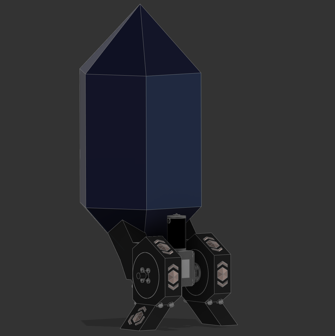
Lastly, since you made it this far, here's a picture of the currently planned feeder - now with 34% more steampunk!
![]()
-
Base Mechanism: Complete
09/03/2022 at 21:51 • 0 commentsWe're back after an extended outage brought on by a double whammy caused by travel and extended downtime on the 3D printer.
The 3D printer is still only back to 90%, but I'm hoping a new leadscrew will fix the last of the issues.
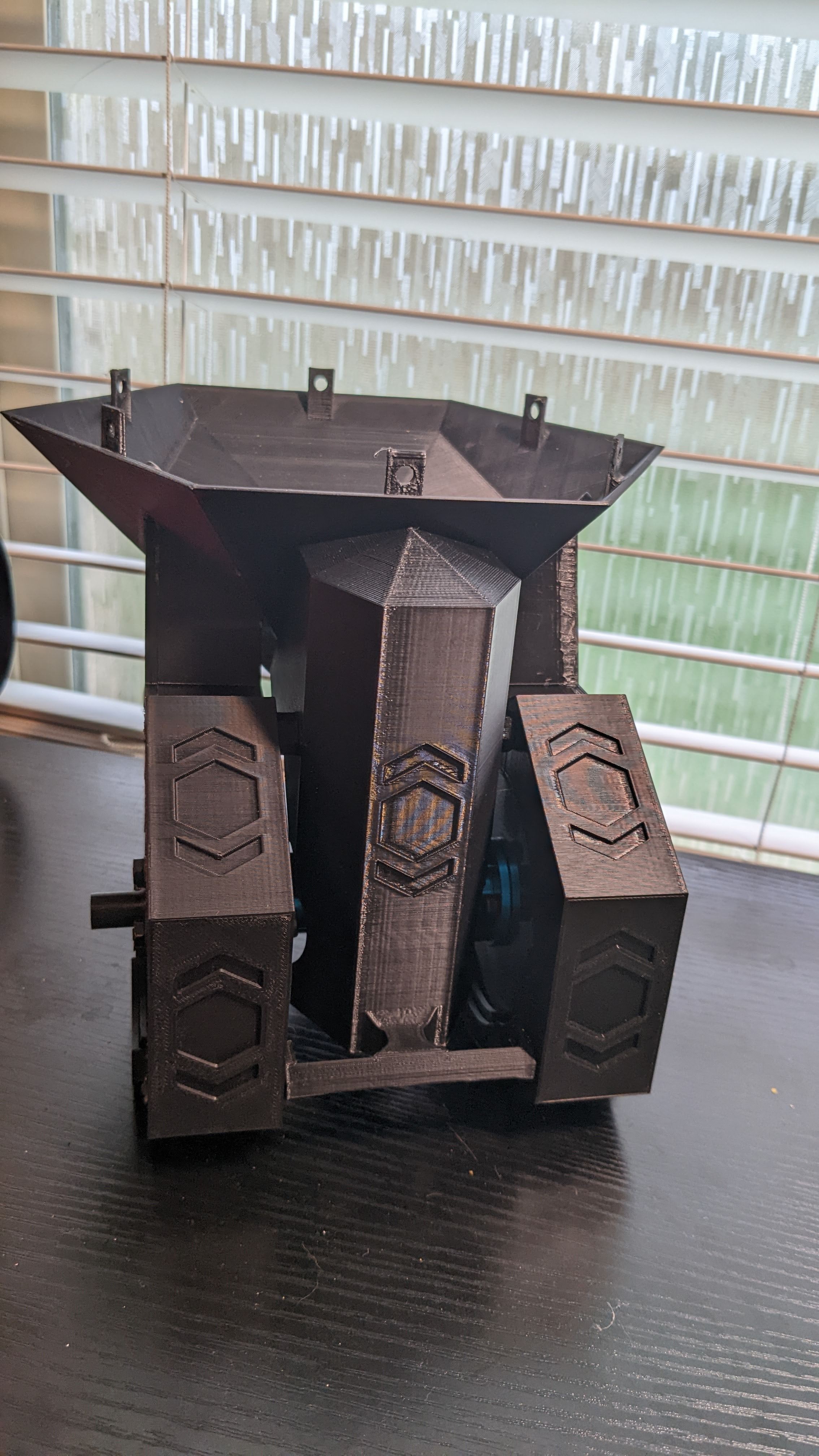
Despite all that, work has progressed. The base mechanism now reliably dispenses food. The crossbracing, wheel guides, and other design tweaks have resolved all the structural problems that doomed the previous effort.
At this point, I'm going to call the base mechanism complete and move on to designing the steampunk-esque piping that will snake around the unit giving it its unique "Aetherpunk" style.
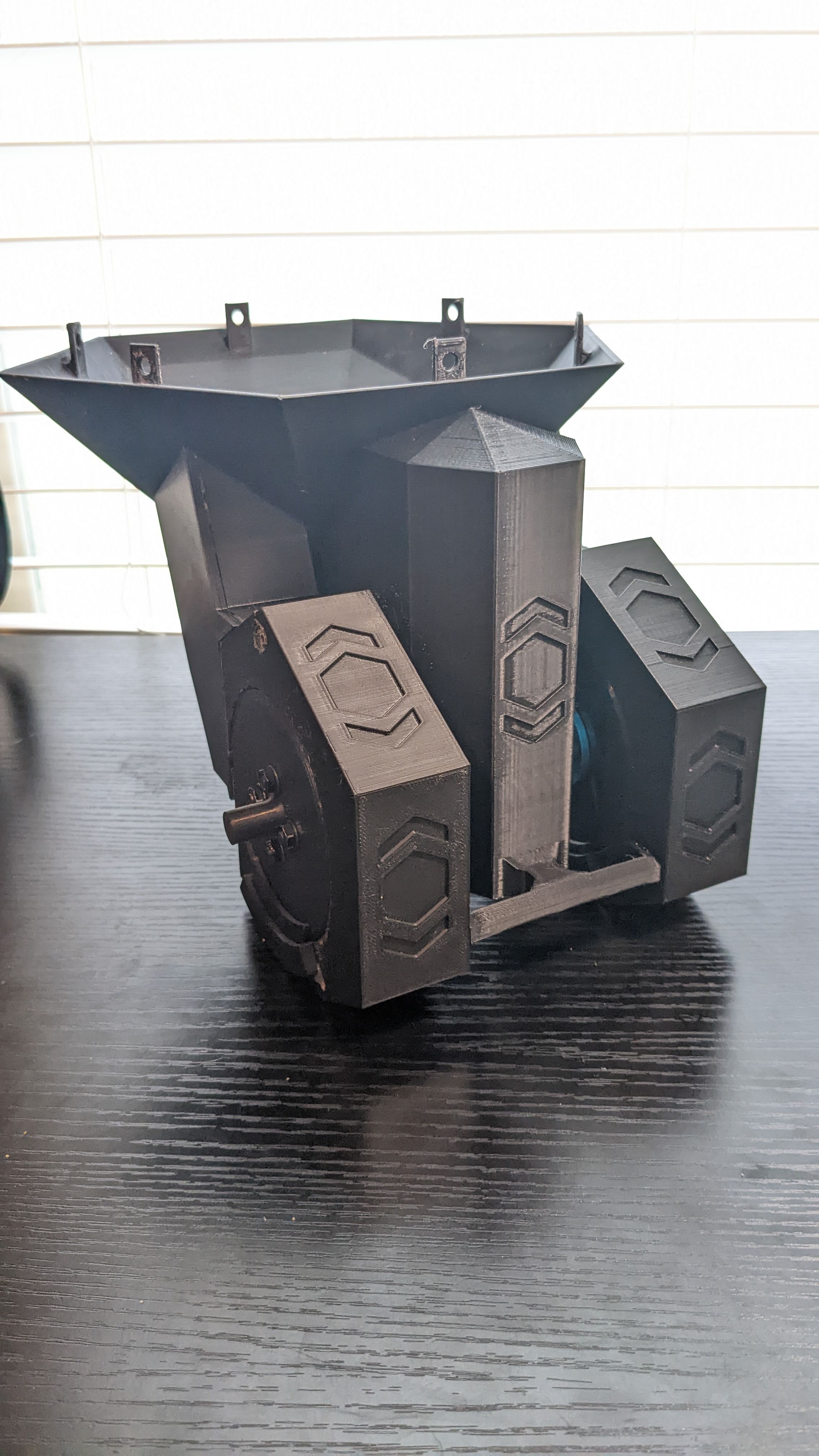
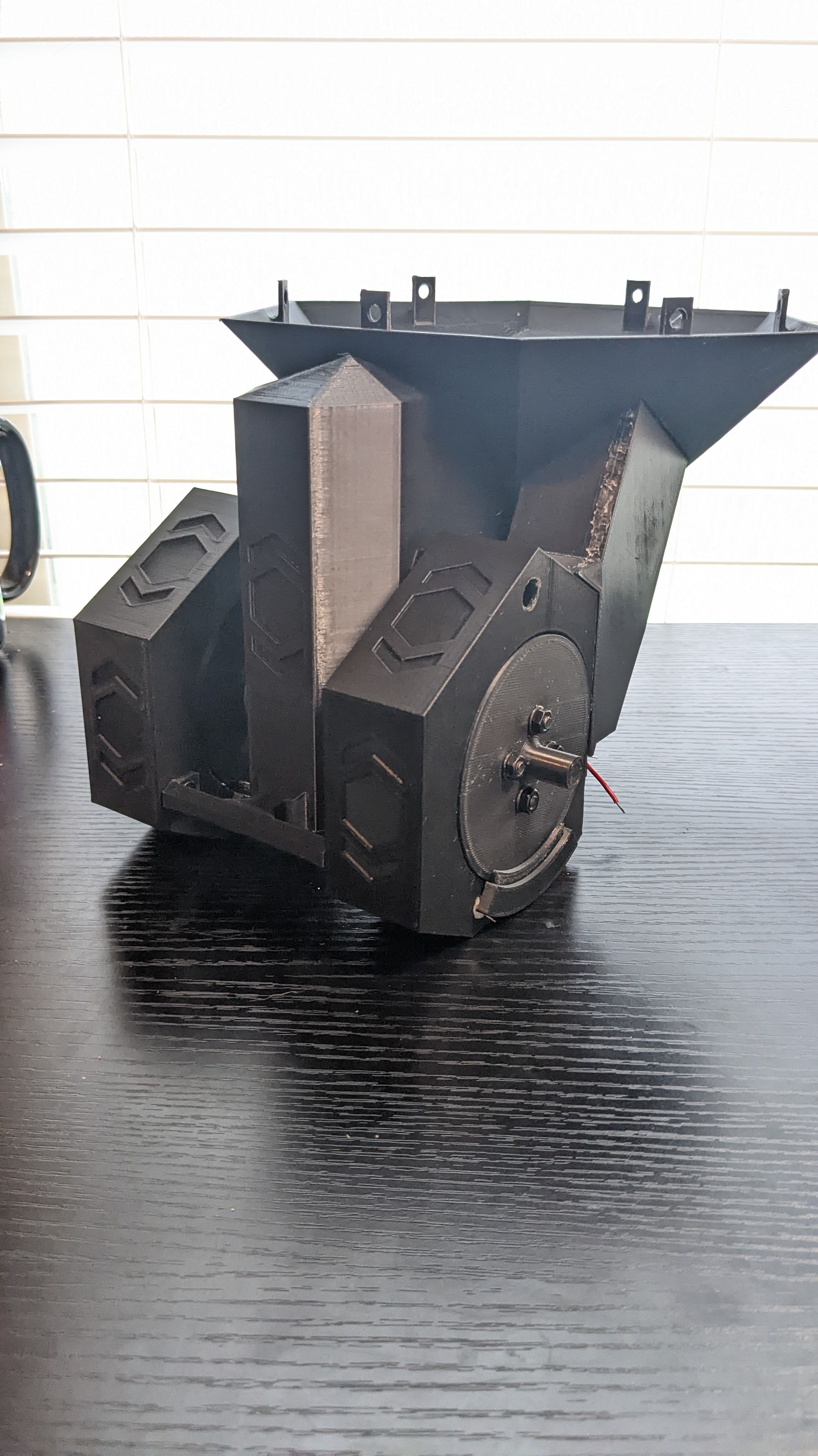
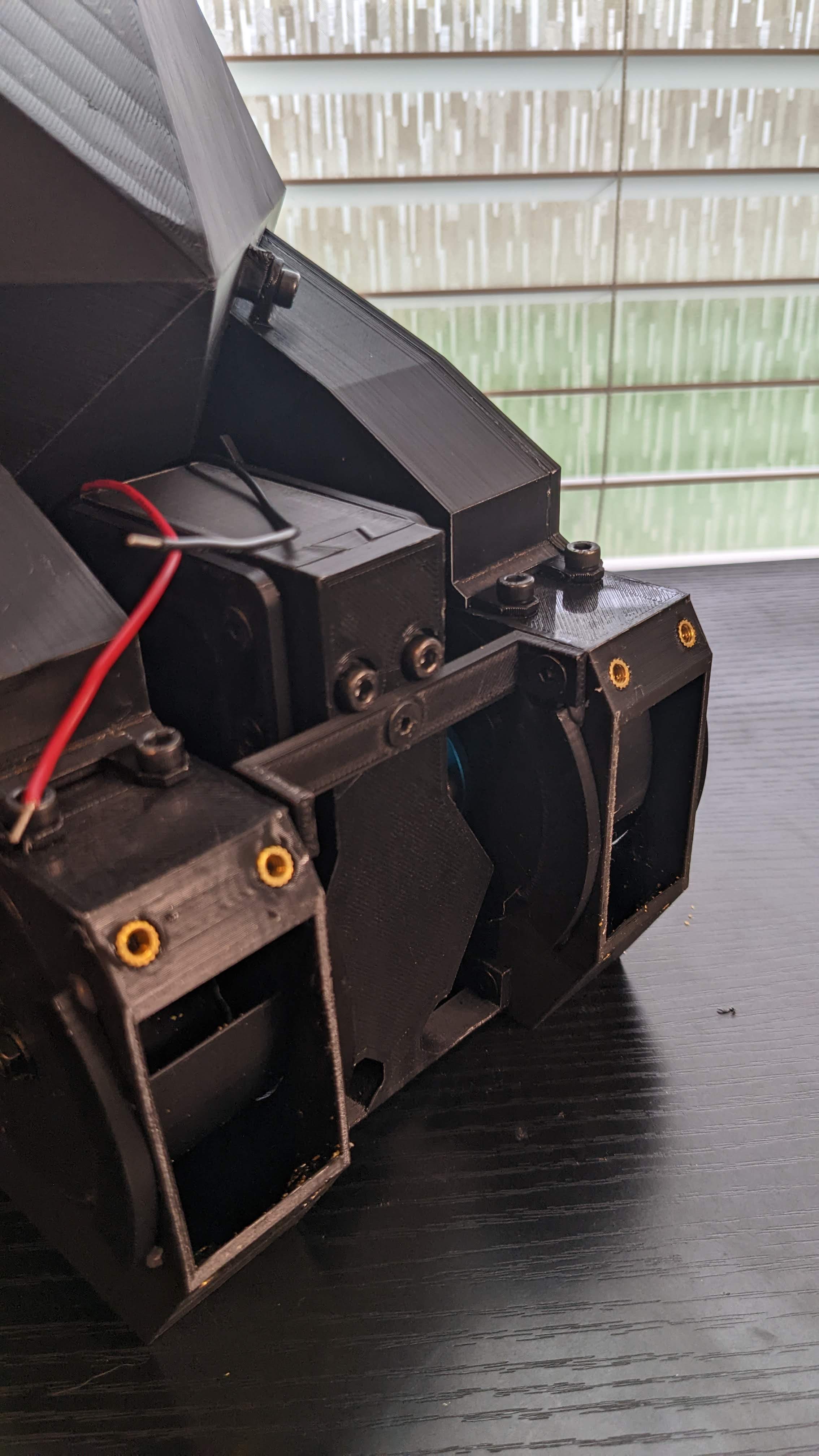
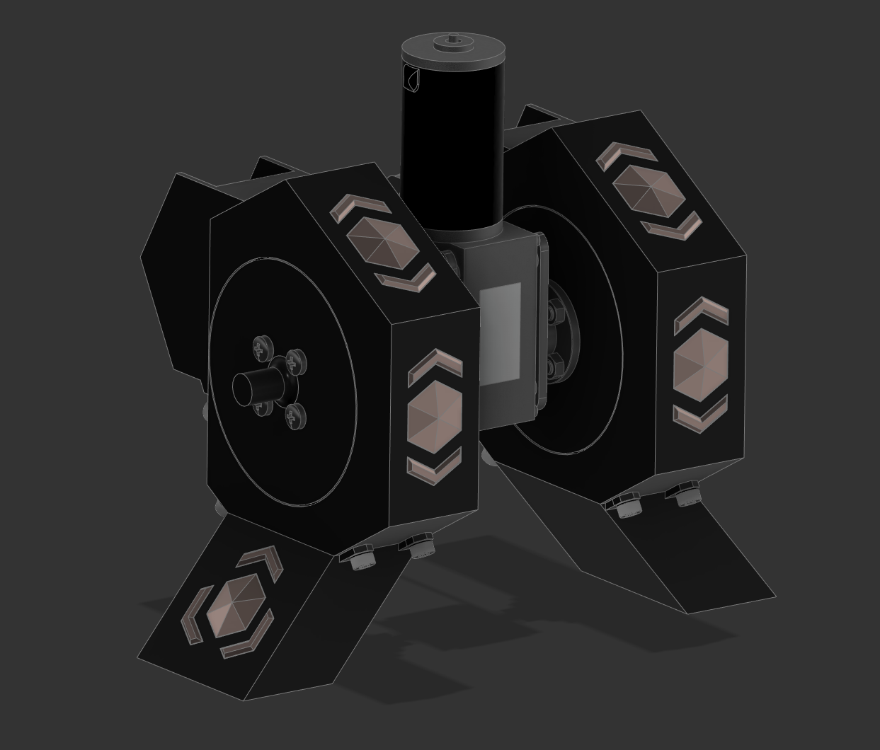
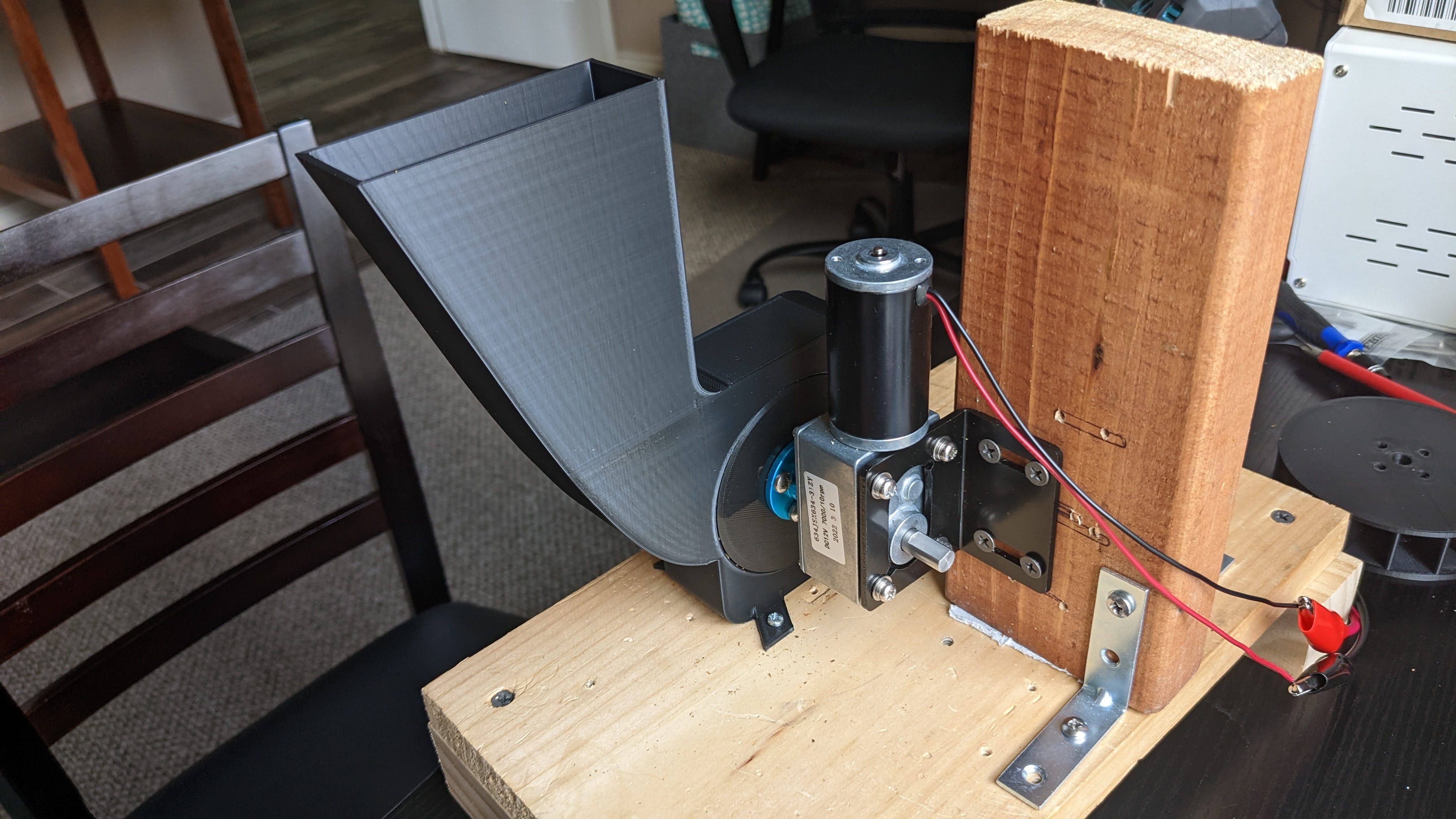
Here are some shots of the completed unit.
![]()
![]()
![]()
![]()
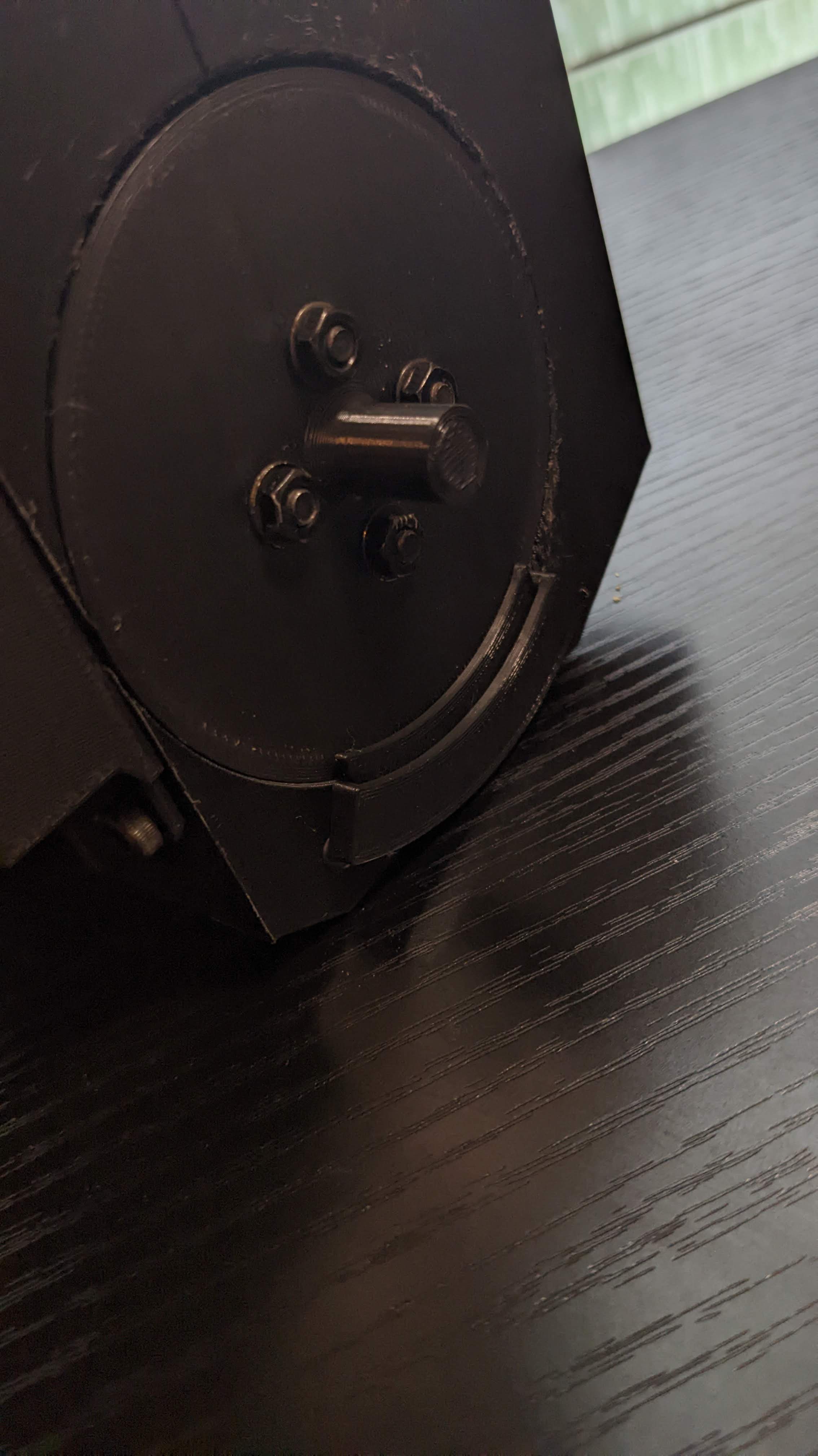
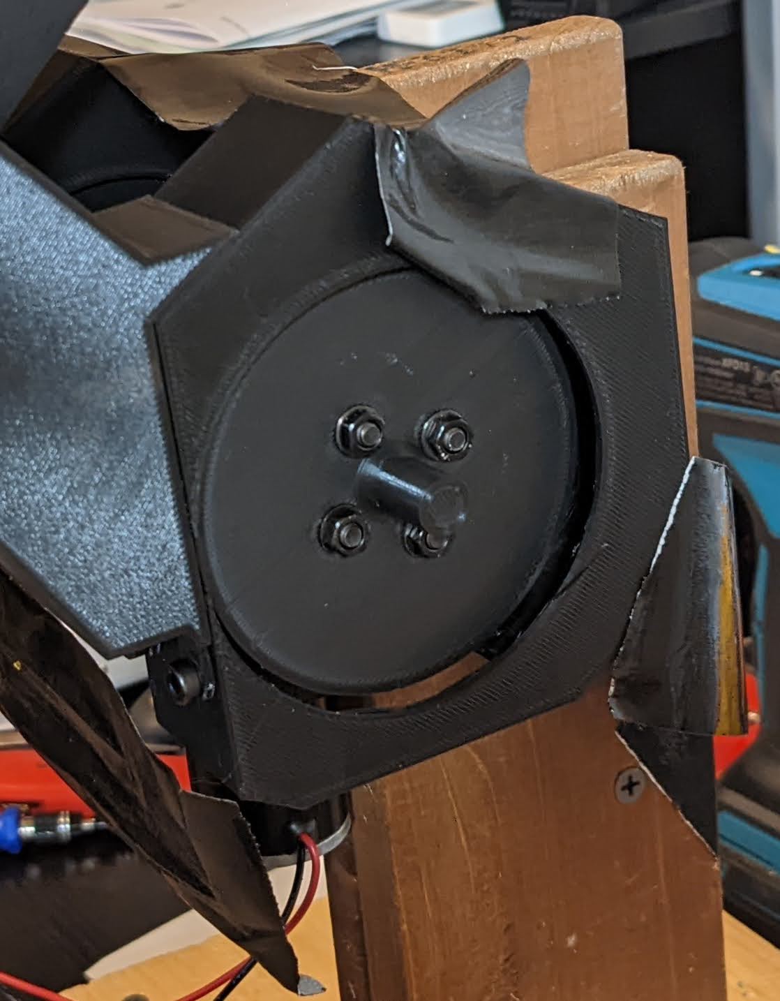
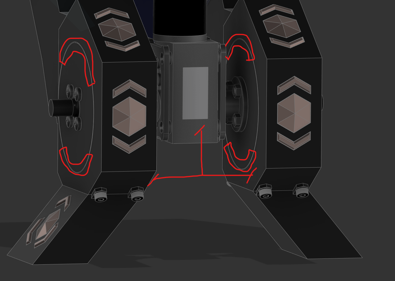
Above: closeup of the wheel guides. The outer sleeve is printed separately and then attached to facility easier printing of the housing. The hot glue was insufficient so I will probably use super glue. After the outer sleeve is installed, the wheel is inserted into the housing, and then lastly the inner piece is slid into the sleeve to lock the wheel in its channel.
![]()
In this shot of the bottom of the mechanism, you can see both the interior wheel guides and the two cross-braces that I added for structural support. You can also see the dovetail join necessary to allow the motor to be installed inside its housing, a late add after the initial build revealed it was impossible to assemble.
I do not plan on building this mechanism again until the final build. This may change depending on how complex the pipe-work gets to be, but I'm hopeful.
Next steps:
- Final cleanup on the model:
- Add access holes to a few screws for assembly.
- Redesign the hopper-to-chute interface because the current design cannot be printed effectively.
- Design pipework around the mechanism. Pipework has a few primary functions:
- Enhance the aesthetic of the design.
- Provide structural support for the fully assembled device, including elevating it off the ground.
- Holding mechanism for the two feed bowls.
- Final cleanup on the model:
-
Crossbracing
07/03/2022 at 22:13 • 0 commentsOne of the findings from the most recent project log, where I built a prototype of the hopper-to-feedwheel mechanism was that the system was extremely flimsy. It required a great deal of duct tape, was all out of tolerance, and all sorts of parts didn't join up right not due to improper dimensions but due to insufficient structural design.
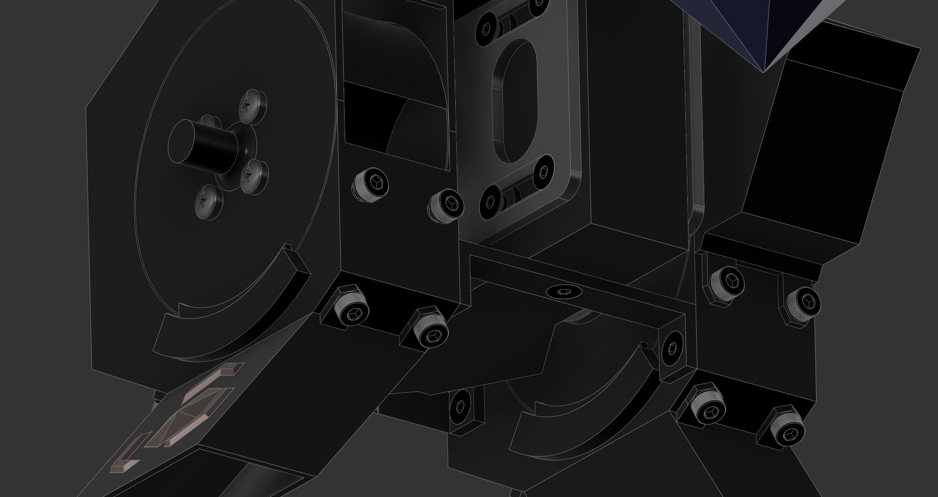
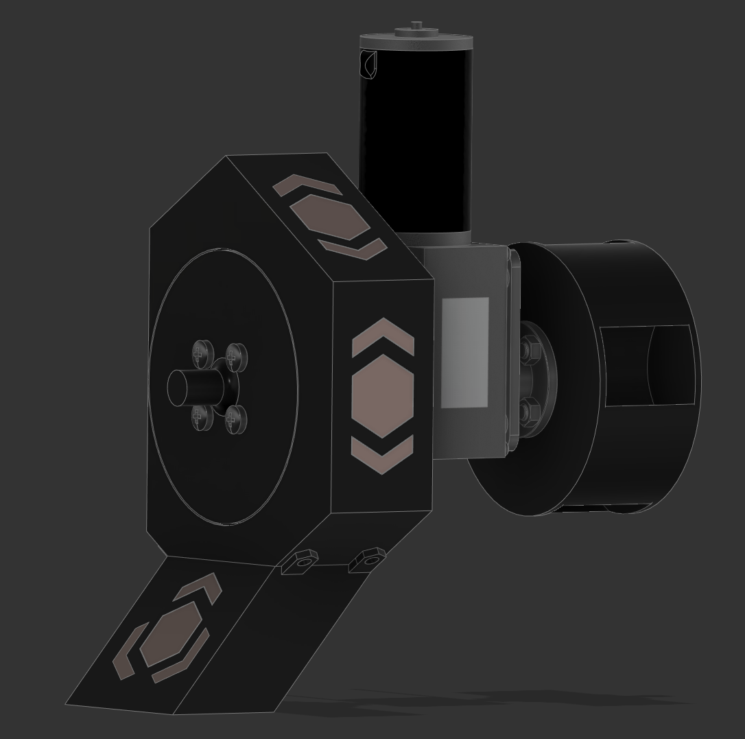
I have now added extensive crossbracing to secure the mechanism. Part of that also included designing the cover that slides over the motor for aesthetic purposes, and I think it turned out well.![]()
Above is a rendering of the full device so far. As you can see, I still have not redesigned the chutes that lead from the hopper to the wheels, because I can't figure out how.
But the cross bracing looks good.
![]()
![]()
Also visible, particularly in the bottom image, are the alignment shims. These slide into their little housings and ensure the wheel stays aligned inside the wheel housing. I made the shim housing a separately printed piece with alignment holes that I will glue into place as an assembly step.
This allows me to still print the wheel housing on its side without a bunch of supports.
Next up will be dealing with the hopper-to-wheel-housing chutes.
-
Double Wheel Attempt 1
06/24/2022 at 01:43 • 0 commentsI have added the hopper!
![]()
The goal is to print this out of translucent blue PLA and put LEDs inside of it to make it look like it is glowing.
I have also printed the bottom feed mechanisms with both wheels and tested it out.
And wow was it bad.
![]()
![]()
![]()
I am ashamed to even post these.
Here are a list of failures:
- I was unable to fit the hopper exit chutes into the hopper in order to mate them.
- I had planned on sliding them in through the top, but they did not fit through the opening. They also could not clear coming up from the bottom.
- See image #3 above.
- As a result, I had to cut off one of the two mounting tabs. This caused the exit chutes to bow outwards.
- This caused the wheel housings to pull outwards, away from the wheels.
- See images #1 and #2 above.
- This caused extensive duct taping to be required, and even this was insufficient to prevent momentary violent jams due to the misalignment.
Changes required:
- Redesign exit chute to allow mating to hopper.
- Add lateral supports between the two hopper containers.
- Further develop design to provide mounting of hopper exit chutes to main support structure so they aren't floating.
- Add flanges around the outside and inside of the wheel housings to keep the wheels from leaving the housing. Note these must be removeable because the wheels install by sliding onto the motor shafts through the housing.
- Don't get impatient and skimp on supports when printing parts.
![]()
And to stay positive, what went well:
- The threaded inserts - these guys worked delightfully. See my previous project log for my learnings about using these guys.
- Dimensions - I've never used a CAD assembly before, so it's very pleasant to make a multi-part 3D printed contraption and have everything just magically be the right dimensions on the first try.
- I was unable to fit the hopper exit chutes into the hopper in order to mate them.
-
Two halves make a whole
06/11/2022 at 21:55 • 0 commentsA coworker pointed out that McMaster Carr has CAD downloadable for many fasteners and other items. Armed with this time, I grabbed a STEP file for an M4-0.7 6mm socket head screw in blazing speed.
Otherwise, not much to report. I have mirrored over all the components on the left side of the feeder to the right side, and will now be working on connecting both halves to a shared hopper.
After the hopper is designed, I'll be adding some pipes to provide primary structure, and a few gears that turn with the feed wheels for aesthetics. Then it will be time to move from mechanical to electrical.
Roadmap:
- Shared hopper
- Pipe primary structure
- Gear aesthetics
- Shift to electrical work
![]()
-
A Brief Aside: Threaded Inserts
06/10/2022 at 01:50 • 0 commentsI've never used threaded inserts before, so I thought it would be worthwhile to learn to use them correctly.
For reference, I bought these.
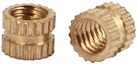
If you're unfamiliar with threaded inserts, they're small pieces of brass with grooves on the outside and threads on the inside. You can secure them into plastic so you have a strong place to screw a bolt into. (Compare this to screwing a bolt directly into plastic - the threads would immediately strip.
![]()
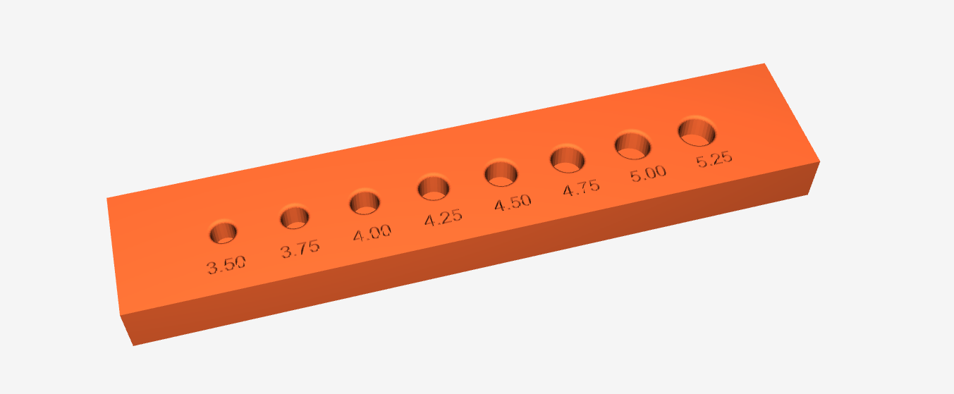
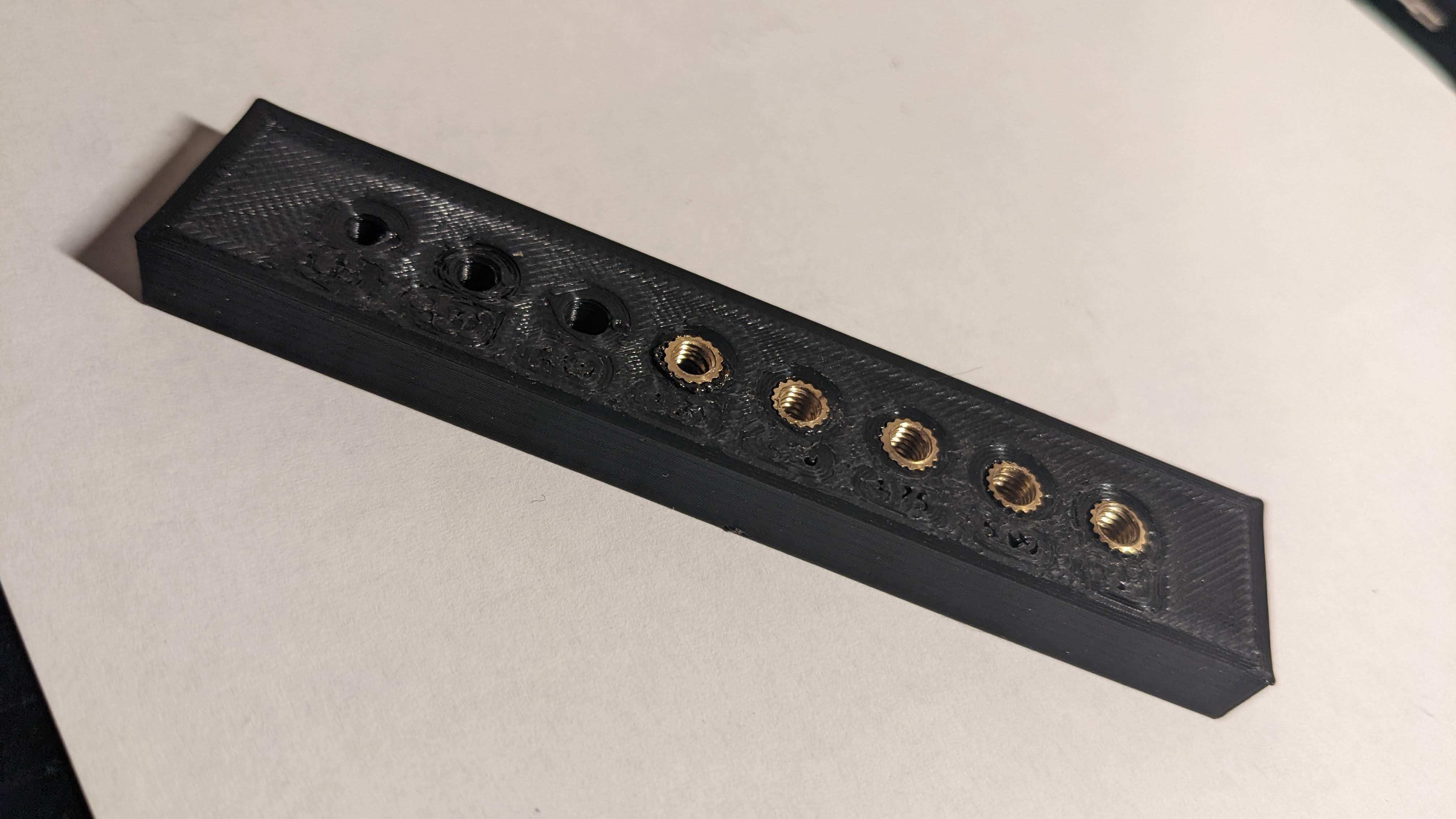
The question is, how big do you make the whole in your 3D print to accommodate one of these? Online guidance varies, so I determined some experimentation was necessary. The outer diameter of the threaded inserts per my datasheet was 5.3mm. As a result I decided to test with sizes from 3.5mm up to 5.25mm, almost the size of the outer diameter. Here's the test rig I made to test these sizes. I've made this available for printing here.
![]()
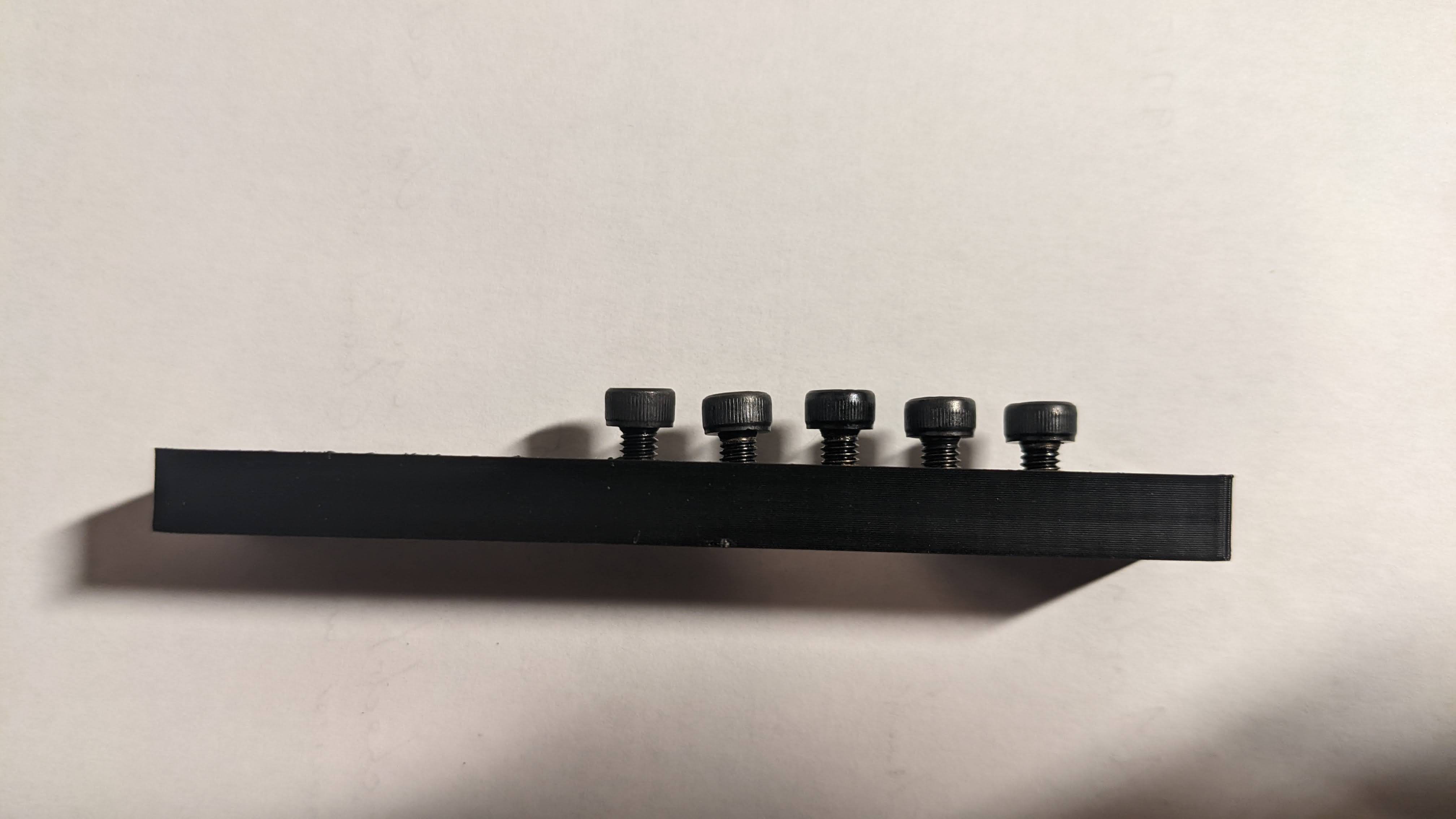
The general installation method for these bad boys is to use a soldering iron to heat the threaded insert up, then push it down into the plastic. This worked admirably. The operation involves pushing them in half way with the soldering iron, and then pushing them the rest of the way with a large flat piece of metal to ensure they're flat.
![]()
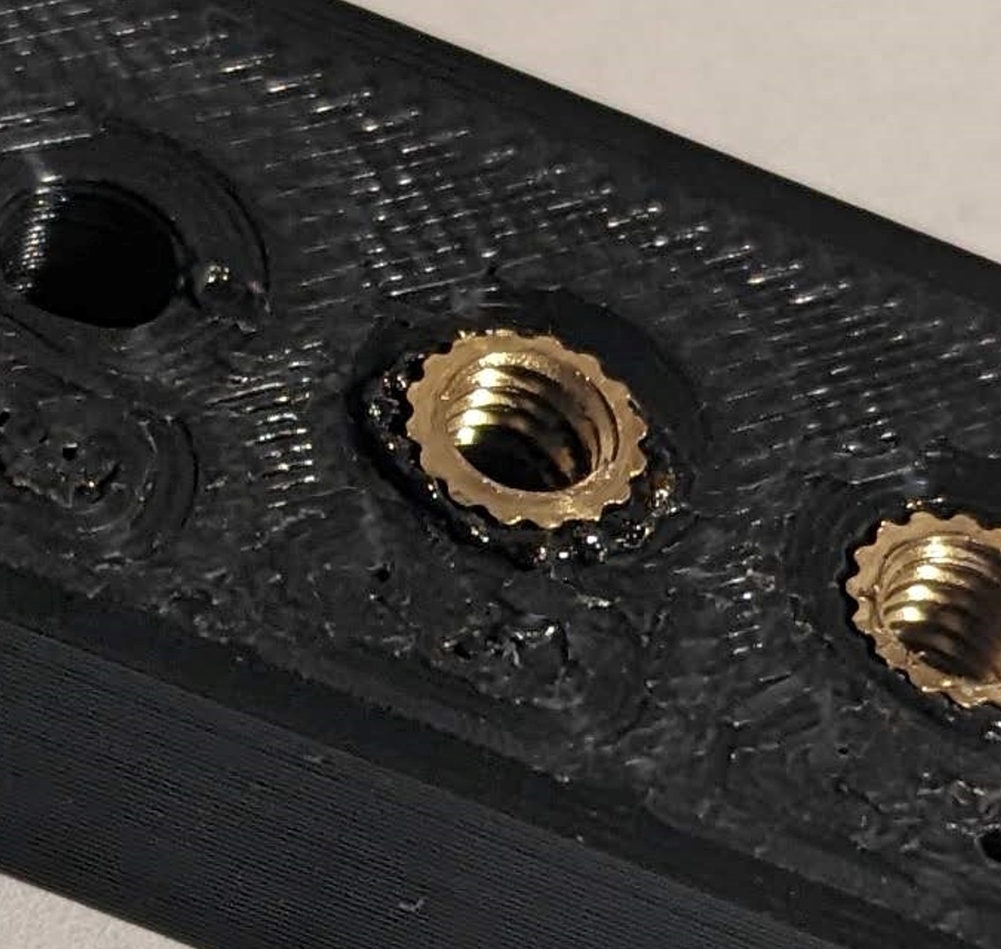
As you can see, I installed threaded inserts in only the five largest holes. By the time I had reached 4.25mm, there was so much extra plastic melting around the insert that it was pushing up the bottom and out the sides.
![]()
I also found that it was challenging to ensure the threaded inserts solidified such that they were vertical. I was using a screwdriver to hold them flat while they cooled. I believe that instead, a large piece of metal would ensure equal pressure was being applied to all sides of the insert, thereby ensuring they cooled perfectly flat. Here you can see that the second-from-left insert in particular cooled off-kilter.
![]()
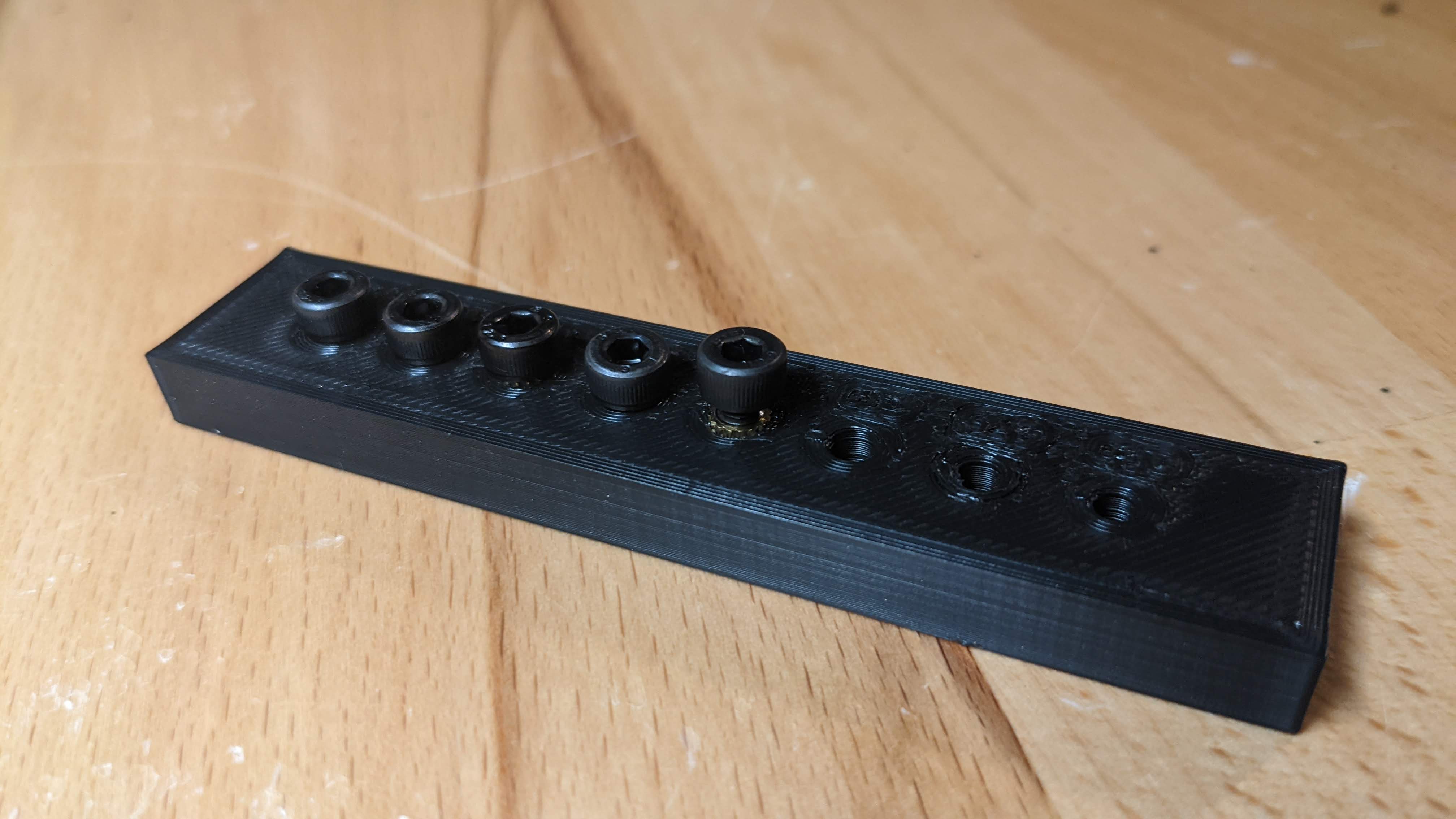
Overall, I found that the experiment was a good success. I felt that 5.00 mm is an optimal size for the threaded inserts. Enough plastic must melt to ensure a good grip is formed on the insert when the plastic cools, but not so much plastic melts that it risks intrusion through the bottom or out the sides.
I'll be using 5.00mm holes for all my M4 threaded insert holes for the project.
![]()
-
On Art and Aesthetics
06/06/2022 at 02:16 • 0 commentsI've now started doing some basic art design. This has forced me to do something I never, in the course of my entire existence, thought I'd be voluntarily doing: art history research.
I can't recommend this article enough. In it, the author analyzes the art styles of the two main factions in Arcane - the orderly, wealthy Piltover, and chaotic, destitute Zaun.
Piltover uses primarily artistic cues taken from the phase of art called "Art Deco", characterized by geometric shapes and patterns. On the other hand, the underworld of Zaun is stylistically inspired by "Art Nouveau".
![]()
The Art Deco style, aka, Piltover, is more appealing to me, and also much more practical for 3D printing and my extremely limited art skills, so I'll be moving to design based on that.
Here are some screencaps from the show I've been using for inspiration. Note the geometric shapes and clean lines.
![]()
![]()
![]()
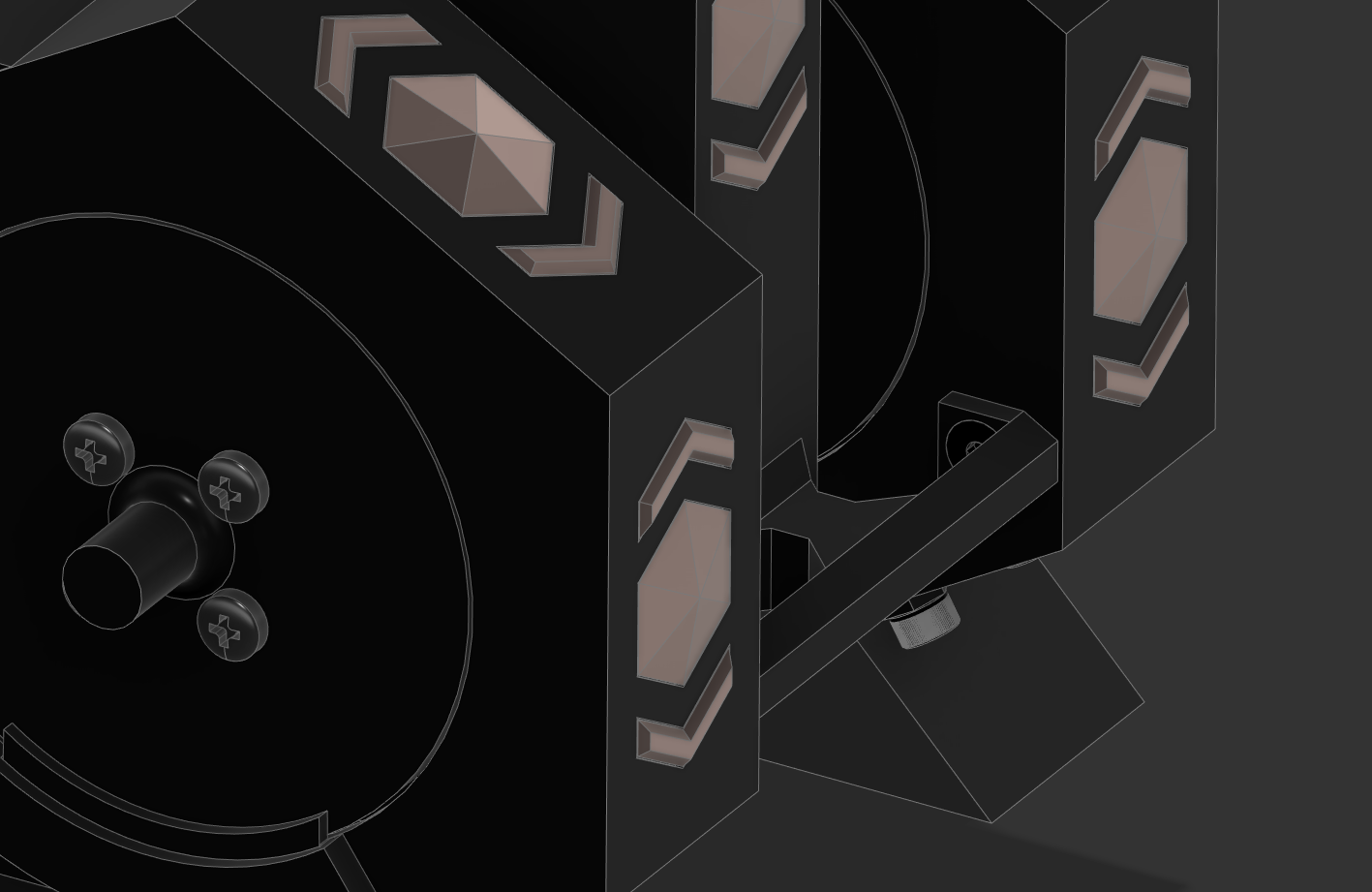
I've decided to theme this cat feeder with hexagons, because they're a very fun mathematical shape, are very versatile, and have lots of fun opportunities.
Here's what I have as a starting point. The copper color are inset pieces that I'll print separately and spray paint copper-colored (color subject to change).
![]()
Finally, it has occurred to me that Arcane is not exactly steampunk, due to the presence of magic. After some research, I've seen a few folks recommend calling this magepunk. There's also a subreddit dedicated to something called Aetherpunk, which I think is pretty similar to what I'm looking for.
-
Double the Wheels, Double the Trouble
06/03/2022 at 00:26 • 0 commentsI am excited to finally have some sort of an assembly coming together!
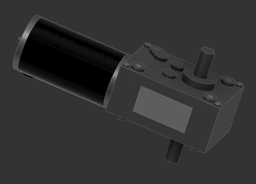
I have modeled the motor using the datasheet and some calipers.
![]()
I have also discovered the magic of GrabCAD for things like standard bolts and nuts.
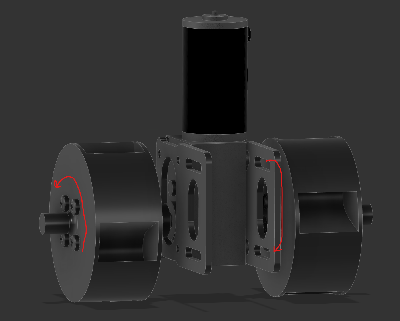
I have now started the assembly model of the actual cat feeder. I have added mounting brackets and the wheels to the motor. Sadly, when I did this, I realized that my wheels are not symmetrical, and so they would need to turn opposite directions in order to work as scoops like intended.
![]()
I could just design a mirror image wheel, or I could redesign the wheel to work if rotating in either direction. I must think on which is the better route to take here.
-
Deployment Mechanism 4 - The Thrill of Victory
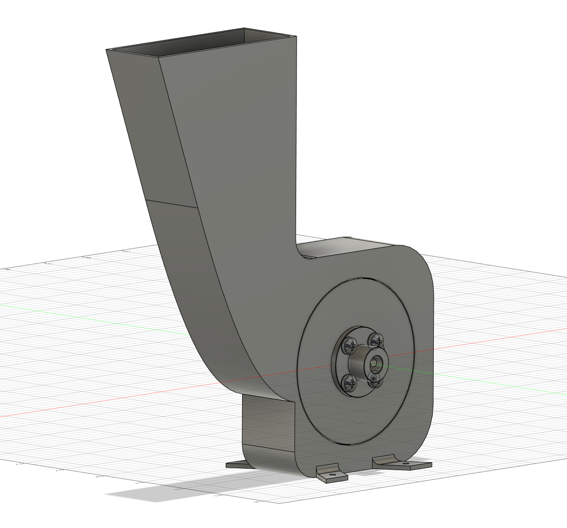
05/30/2022 at 18:45 • 0 commentsWith no jams, highly reliable feed deployment, and simple geometry, I'm proud to present after four iterations, the feed mechanism for the Feline Sustenance Amplifier!
![]()
Notice the much higher baffle, resulting in far better access to the wheel from the feed chute. Also notice the entire chute has moved laterally much closer to the wheel.
![]()
After extensive tests, no jams occurred, and food moved consistently and smoothly through the deployment assembly.
![]()
What's next? I don't know. I'm so excited to finally have this working I haven't thought much about it.
I think next steps will be:
- Modeling the motor
- Creating a motor mounting scheme that allows access to both sides (unlike this one)
- Getting two feed wheels going at the same time.
Looking further ahead, other things that need doing:
- Determining how to design some nice steampunky big gears
- Determining what kind of pipes I want to use for aesthetics
- Designing artistic design which manage to capture the inspiring melding of steampunk and art-deco so effectively used in Arcane.
![]()