 Sam Smith
-
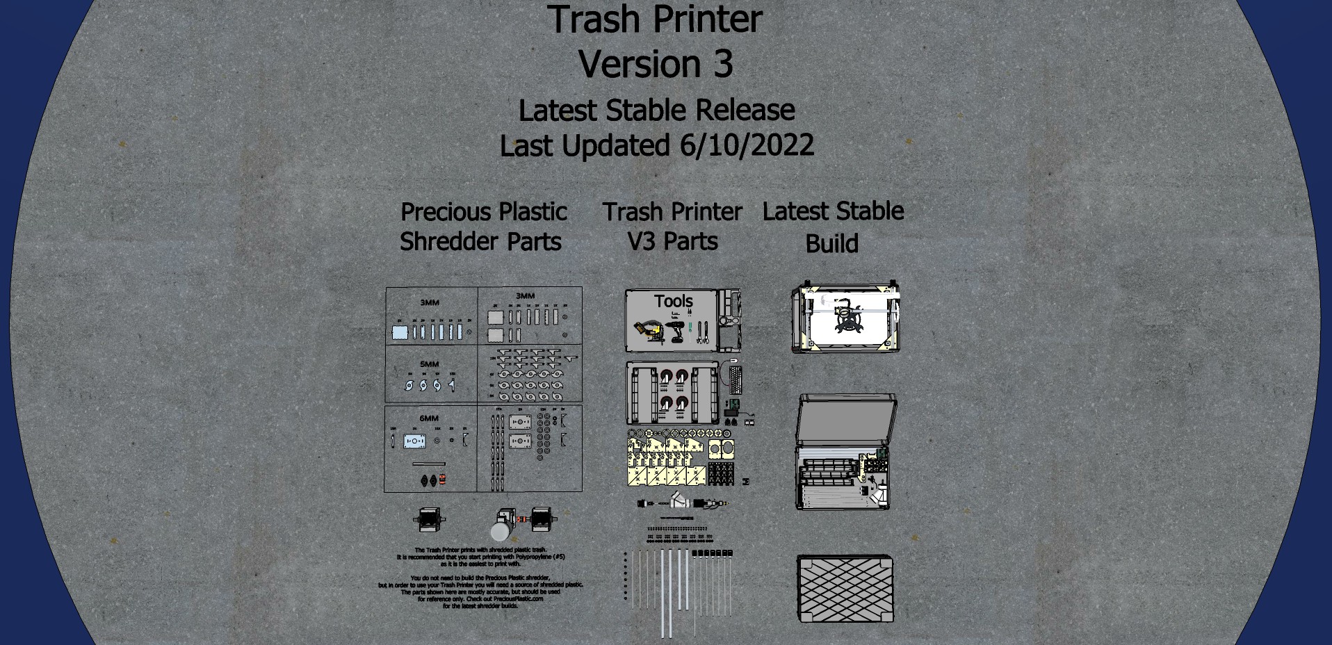
1Download the Plans
I am fascinated by the idea of disruptively useful information.
Disruptively useful information is information for how to do or make something so incredibly useful that it challenges the status quo. In order to be disruptive, disruptively useful information cannot be simply a neat idea or a promising technology, it must be the specific practical application of a useful idea. In order to be useful, people must be able to understand how to do it and why to do it, so well that they actually do.
Disruptively useful information must be a complete unit of information that contains ALL of the information required for the idea to be replicated anyone, anywhere, without permission. If you have access to disruptively useful information, you already have everything you need.
![]()
I do not believe that the plans for the Trash Printer counts as disruptively useful information - not yet anyway. An idea like the Trash Printer can't possibly be disruptive unless a lot of people can actually do it too.
The Precious Plastic open-source shredder is one of the best examples of disruptively useful information that I know of.
The coolest thing about the Precious Plastic machines, IMHO, is that the plans are freely available for you to download, and if you have access to them and the means to follow them, you and your friends can build your own plastic recycling workshop. Disruptively Useful Information spreads like a meme.
If you see it, and you like it, you can copy it, and you can change it. You can do whatever works for you without asking for permission, and if you figure something out that works particularly well for you, you can share that with others. That kind of rapid, global, decentralized hacking is what gives me hope that we may actually be able to find ways to adapt to the challenges that we face, as quickly as we need to, come what may.
If you do replicate your own version the Trash Printer, please let me know by commenting on this page or on my Patreon. I would love to see photos of the stuff you build with it.
If you make improvements, please post your changes in the Github Repo.
If you appreciate the work that I've put into this project so far, consider becoming a Patron! Everything that I make is posted publicly for everyone to see, but patrons give me a working budget to keep hacking, and get access to a private Discord server so we can chat while I'm livestreaming.
My Patrons currently give me a monthly budget of around $650 a month, and they're the reason I've been able to keep hacking on this all these years. I'd love to get up to $1200 a month, because then I could buy, build, and livestream a new Trash Printer build video every month. If you'd like to see that happen, and have a buck or two to spare, you know what to do.
-
2Build your Community
The Trash Printer will probably cost you somewhere between $800-1500 for you to build, depending on what tools, skills, and parts you have access to. A lot of the parts can be found locally, and/or used, or scavenged from old 3D printers.
The shredder is not required, but without a shredder of some kind you will not be able to print with your own trash. You can check the Precious Plastic map to see if there is workspace with a shredder near you, and see if you can get shredded plastic from them! If not, consider starting your own!
Like the other Precious Plastic machines, the Trash Printer can be an expensive and difficult tool for one person to build, but a very affordable and easy tool for a small community of people to build.
So if you want to build one, start by asking for help! Talk about it with your friends and comrades. Pitch it to your school, business, city, or maker space. See who has the skills, space, spare parts, tools, and time or money to help make it happen. DIY means do it yourself, but don't do it by yourself!
-
3Gather your Tools
You can watch the FULL 12 hour Trash Printer V3 Mini build video here. I wouldn't want to watch the WHOLE thing if I were you, but it's here for reference, in case you get stuck. Sorry about the audio, this was my first attempt at livestreaming an entire build, but it hopefully won't the my last. Doing a live-build from start to finish is a great way to iterate on the design, and build new documentation in the process!
To assemble the Trash Printer, you will just need a few basic tools:
Access to a laser cutter, CNC router, or 3D printer (ask your local maker space!)
- Jigsaw with 1.5” offset from guide to blade (“fast wood” bit)
- Power Drill or Impact Driver
- Step Drill Bit
- 5/16” Drill Bit
- 11/32” Drill Bit
- Metric Hex Key Set (3mm hex usually comes with the Shaft Couplers)
- Wire Cutter/Strippers
- Philips Screwdriver
- ⅜” Deep Socket
- Hex Driver and/or ratchet
- Adjustable Wrench (Knipex highly recommended)
- Small flathead screwdriver
- Tubing Cutter
-
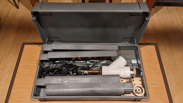
4Collect your Parts
![]()
Check out the files folder in the Files Section for the digital design files. The parts you will need should be easily accessible from just a few sources:
Digital Parts - Use the digital design files to make these parts, or buy them from someone else.
Hardware Store Parts - Many of the Trash Printer parts can be found at a local hardware store.
Amazon Parts - A few of the parts are a bit more specialized, such as the Geared NEMA23 Stepper Motor and lead screws. These parts are readily available on Amazon. Click this link to see my public parts list. If you figure out a way to acquire some of these parts elsewhere, by all means do that, but this Amazon list is provided for reference.
Harbor Freight - I'm using a Harbor Freight service cart, which is cheap and readily accessible in many US cities. You can order a nearly identical one online, but you may need to make some modifications to the parts if you do. I also got my auger drill bits, SAE drill/tap bits, step drill bits, and hand tools at Harbor Freight.
V1Enginneering.com - I highly recommend ordering your control board kit from V1engineering. You can use other boards, but I know their parts work and their shipping is fast.
-
5Assemble your Extruder
![]()
First, let's assemble the extruder, so we can just drop it onto the printer later!
There are two sets of spacers, labeled B1-B7 for the Bottom assembly, and T1-T2 for the top assembly. There is also an extruder motor shaft coupler spacer, labeled E1.
You can cut extra copies of B7 and T2 to act as spacers. The file names indicate the number of that part you should cut. This lets you account for different material thicknesses, and also adjust how far the auger extends into the barrel, by adding these spacers as needed.
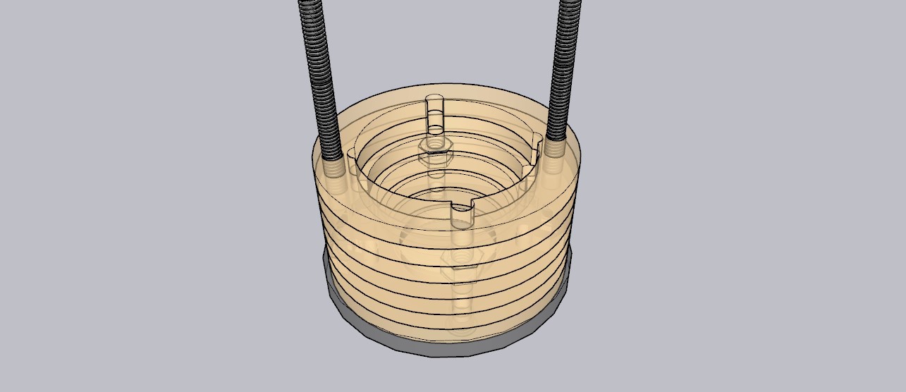
1. Assemble the bottom assembly. Stack B1-B3, and put 1/4"-20 nuts in the hexagonal holes. Then stack B3-B6+ on top of that.
![]()
2. Insert the 8" 1/4-20 hex bolts up through the bottom.
3. Flip the assembly over and place the 3/4" NPT pipe flange on top, then screw in 2x 1.5" 1/4-20 bolts into the captive nuts you placed in B3.
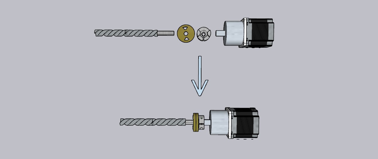
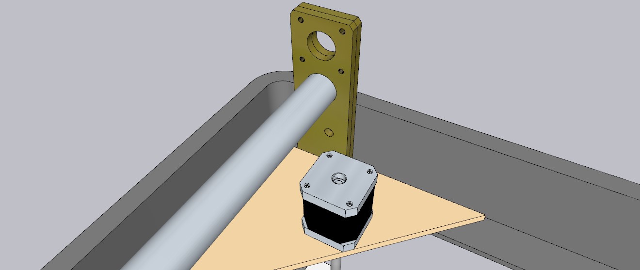
4. Assemble the top assembly - First, attach the 12MM plum coupler to the the motor shaft, and tighten it down.
![]()
5. Insert the bottom assembly into the 3" PVC plumbing wye, and place the motor/auger assembly down through the top, to see where the motor should be placed. You want the auger to extend into the barrel by about 1/2-3/4" of an inch. Place the B2 spacers above or below the T1 motor mount spacer to get the height just right.
6. Attach the T1 motor spacer to the motor, using 4x M5 bolts. If you are putting the T2 spacers above the T1 spacer, make sure you do that first.
7. Slide the top motor assemble through the 8" hex nuts, making sure the bolts are oriented so they don't block the hopper, and then tighten it all together with 2x 1/4-20 coupling nuts (I use coupling nuts because they are taller and easier to secure than regular nuts)
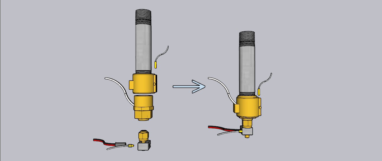
8. Now assemble the barrel assembly. Take the 4" x 3/4" NPT nipple, and screw on the 3/4" FNPT to 1/2" FNPT adapter, then screw the 1/2" MNPT to 3/8" Compression Fitting into that. You don't need to tighten these down too much, hand tightening, or a 1/4" turn with a wrench should do it.
![]()
9. Unscrew the compression fitting, and replace the compression ring with a 3/8" compression insert, then screw the fitting back on and tighten it down until the insert is straight and secure. Tightening this one with a wrench is a good idea.
10. Slide the 30x30mm or 35x35mm band heater up the barrel so that it fits around the 3/4-1/2 fitting.
11. Insert the cartridge thermistor in the free space between the hex of the adapter, and then tighen the fitting down, making sure the thermistor is making firm, complete, direct contact with the metal, and that no plastic or heat shrink is in contact with the heater band.
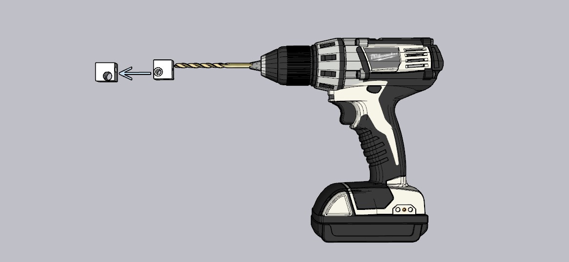
12. Modify the hot end by drilling out the M6 threaded hole with an 11/32" drill bit. If you're using the hot ends I recommend in the BOM, this will leave one of the thermistor taps open to tighten the hot end in place. If you're using a different hot end, you may need to drill a hole and tap it.
![]()
13. Slide the hot end over the compression insert, and use one of the small M3 threaded inserts that come with the hot end to tighten the hot end down onto the insert.
14. Screw in the threaded thermistor into the same port.
15. Slide the 24VDC heater cartridge into the hot end. It should just press fit in, but if it doesn't you can add a bolt to tighten it down.
![]()
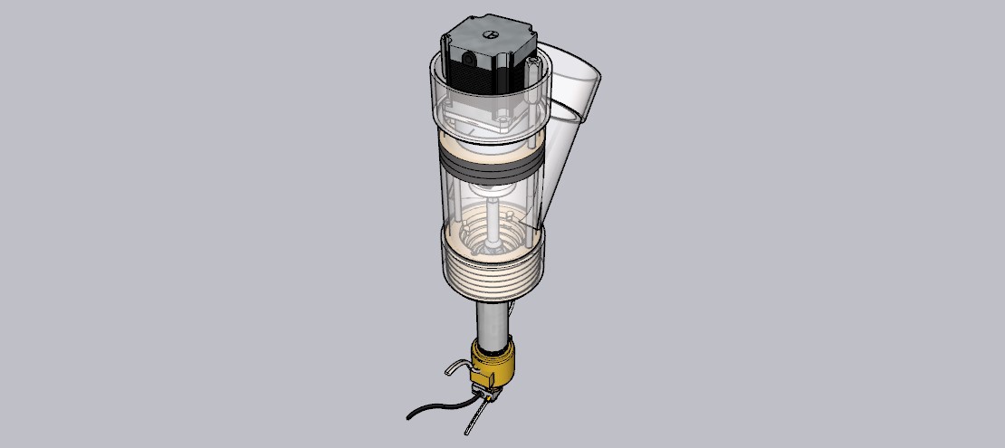
16. Screw the 3/4 Barrel assembly into the flange, and hand-tighten. This part doesn't need to be tightened with a tool, just as tight as you can with your hands.
You did it! Take a break, drink some water, and then move onto assembling the printer. You'll be trash printing in no time!
-
6Assemble your Printer
You can check out the interactive model for the Trash Printer on the SketchUp 3D viewer, or download it from the SketchUp 3D warehouse. You can use this model as a reference to see how all the parts go together, and you can also use it to modify the parts if you need to.
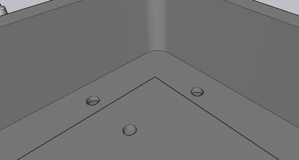
1.Drill out holes through top deck of cart, 4 for each corner, using an 11/32" drill bit, and using the existing bolt holes as guides.
![]()
2. Drill 4 holes in the center of each side of the upper deck, so that you can fit the jigsaw blade in. Then cut out the bed from the top deck using a jigsaw with a 1.5” offest from edge to blade, this will let you use the edge of the cart a guide. Make sure to lay down a tarp or painters plastic (HDPE, #2) so that you can collect the shavings when you're done.
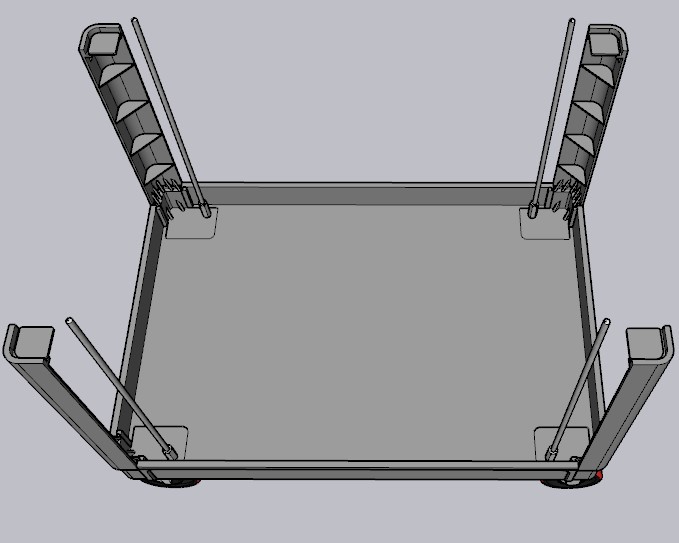
3. Mount the caster wheels and upright supports to the bottom deck, using 2" x 5/16” bolts. Leave the 4th, innermost hole open for the leadscrews, and thread the bolts up through the bottom of the cart. Tighten down the first 2 with 5/16" nuts, and then secure the 3rd (closest to the long side) with a 5/16" coupling nut.4. Screw the 4x 5/16" x 24" threaded rods into the coupling nuts.
![]()
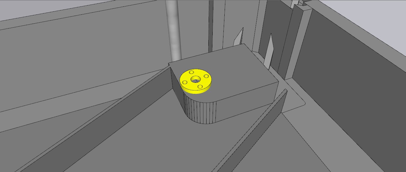
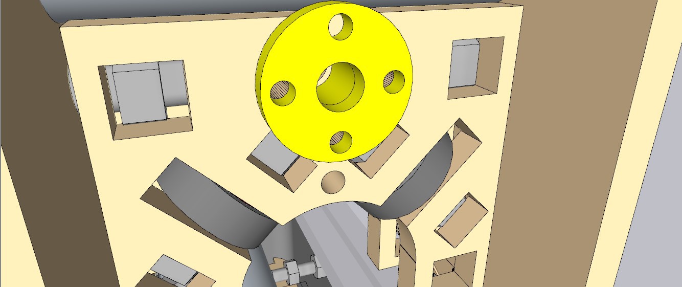
5. Flip the bed you cut out from the upper deck over so that the cross braces are facing up, and then press-fit the 4x lead nuts into the one remaining hole you drilled out. Depending on fit, you may or may not need to secure these with M3 bolts.
![]()
6. Place the bed onto the lower deck, and line it up with the inner most holes.
7. Place the upper deck on top of the uprights, inserting the threaded rods through the holes you drilled.
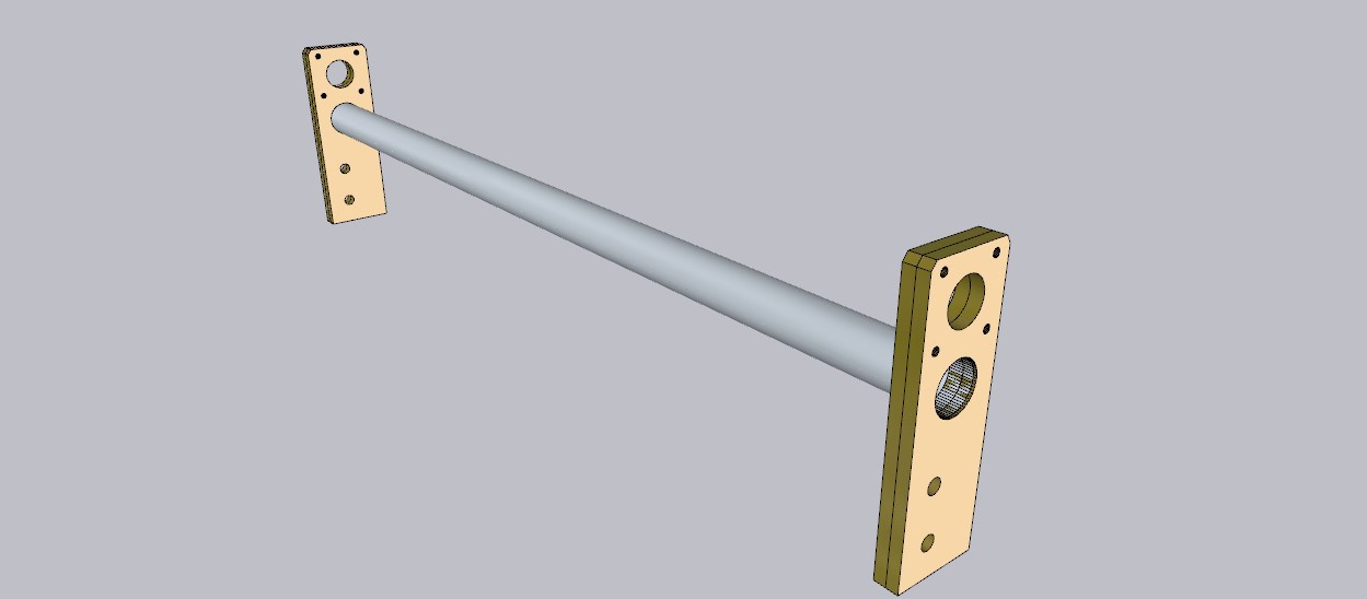
8. Attach the 600mm T8x8 leadscrews to the 4x Z motors with the 5-8mm shaft couplers.
9. Attach the Z motors to the Z motor plates (Z1) using 4x M3 x 10mm bolts
![]()
10. Place the Z-motor assembly on the top deck, and line it up with the two holes. These holes are intentionally left larger than they need to be to give you some wiggle room. Line up the leadscrews with the the lead nuts in the bed, and screw them in by hand until the Z1 motor brackets are flush against the top deck. Secure with 5/16" nuts onto the threaded rods, and a 5/16 x 2" bolt and nut on the side without the threaded rod.
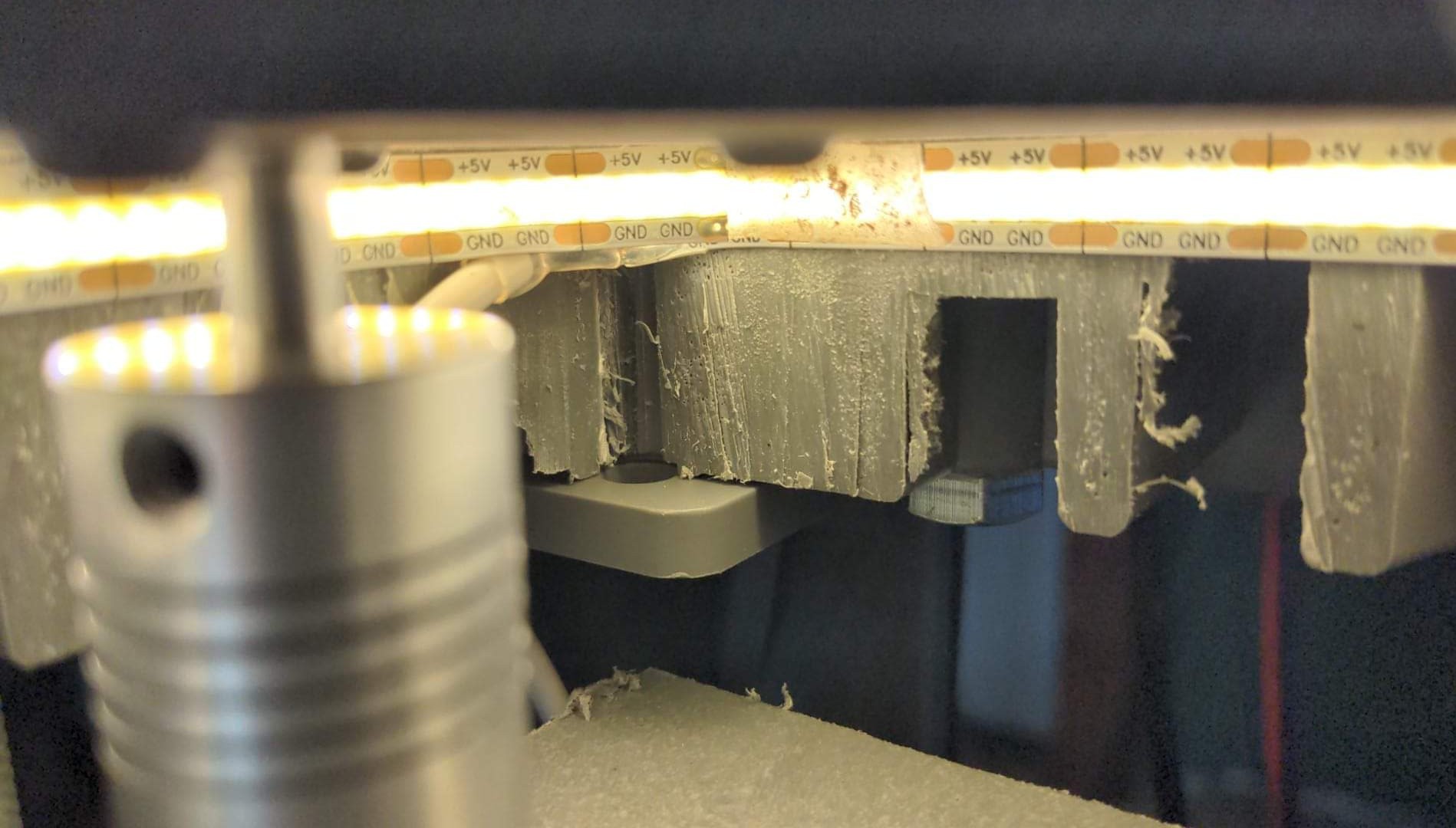
11. (Optional) Install LED light strip - take off the adhesive and stick the light strip to the edge of the cut you made to cut out the bed, the 2M strip fits the Trash Printer Mini PERFECTLY! This is optional but looks awesome, costs $12, and gives you lots of light to work by.
![]()
12. Use a tubing cutter to cut the 1" OD rails to length (2x 16.25" and 2x 29.5"– for mini and 2x 24" and 2x 35" for regular)
13. Press-Fit short rails into Y upright mounts (Y1, 2x per side)
![]()
14. Place Y Rail Assemblies on to top deck, using Z1 mount indents as guides.
![]()
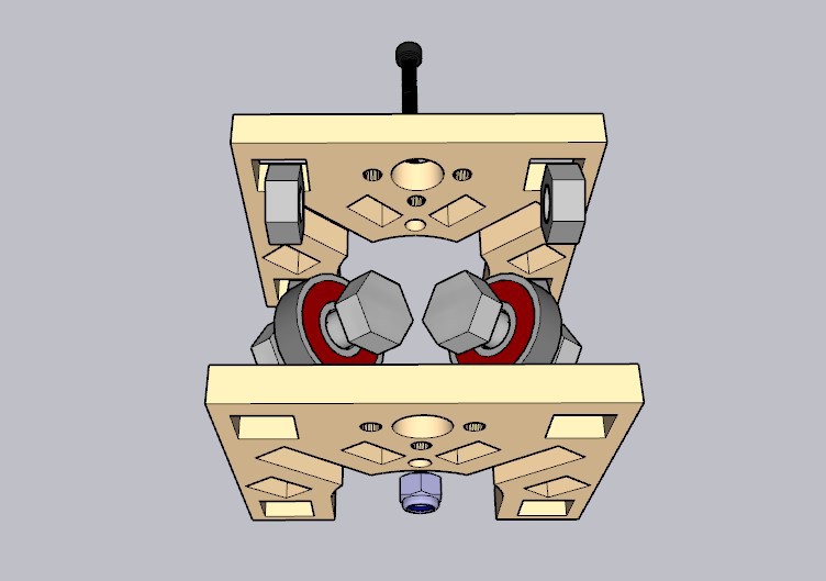
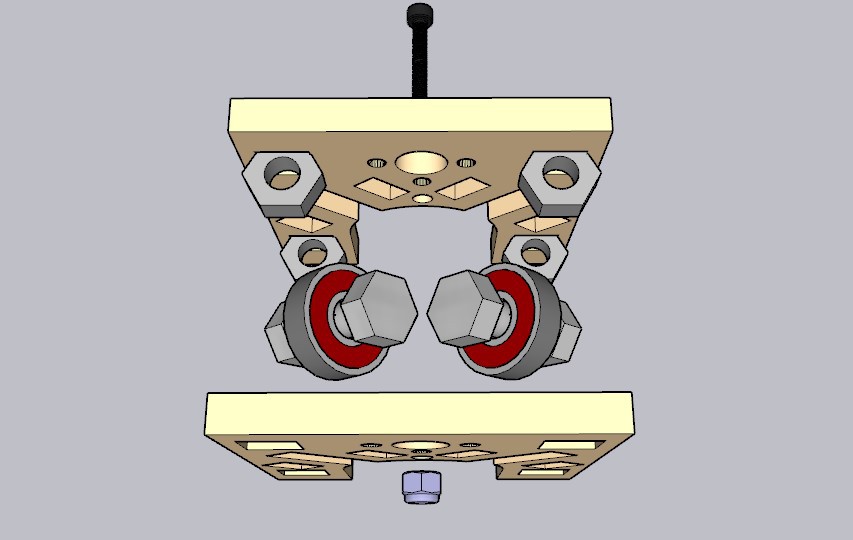
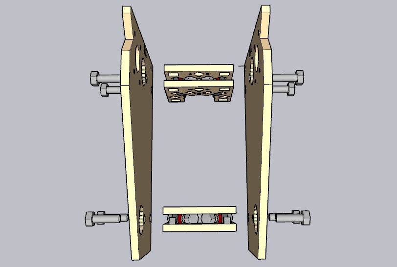
15. Assemble rollers - The rollers come in two sizes - R1 for the Y rails, and R2 for the long X-rails. For the R1 rollers, place the 5/16" captive nuts facing out towards the sides. For the R2 rollers, place the captive nuts facing up/down.
![]()
![]()
16. On 3 of the rollers - 2 of the R1 rollers, and one of the R2 rollers, install lead nuts on the corresponding holes. If you face the leadnut inward, it will buy you a few more mm of travel. Secure with 2x M3 bolts/nuts.
![]()
16. Attach a shaft coupler to Y stepper motor shaft.
17. Assemble 2x Y-roller assemblies, and install one stepper motor/coupler on the right-hand side, before attaching the final outer plate.
![]()
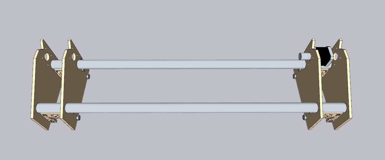
18. Press Fit the longer X-rails into the Y roller assemblies.
![]()
19. Place the completed roller onto the shorter Y rails, and test. Adjust the rails as needed. When everything is straight and rolling smoothly, mark the holes in the Y1 plates on the cart, and drill them out, and bolt them in place with 5/16" x 2" bolts and nuts. The cart walls are slightly off 90 degrees, so you may need to add some washers or spacers to the upper bolt holes to make them perfectly vertical.
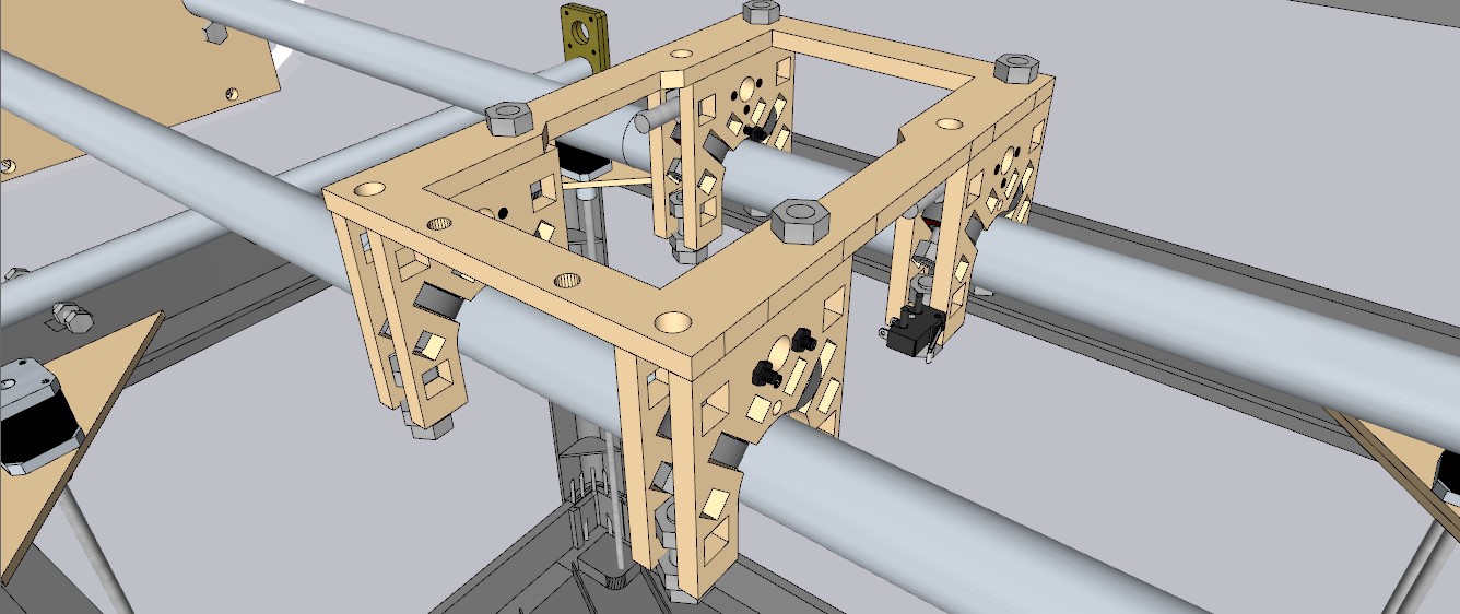
20. Attach the 4x R2 rollers to the top X plate with 5/16" bolts. Place on the X rails.
![]()
21. Attach the SSR to the matching bolts on the X1 plate.
22. Attach the X1 plate from the bottom.
![]()
23. Slide the X carriage assembly to the right side with the stepper motor, and thread in the long lead screw (600mm for Mini, 700mm for regular) Attach to the shaft coupler, and tighten with an M3 hex key.
24. Install shaft couplers to 2x Y steppers.
25. Attach Y steppers to rear Y1 plates, using 4x M3 x 15mm bolts
26. Roll the assembly towards Y steppers, and then thread in the 2x Y leadscrews (400mm for Mini and 600mm for Regular). Attach to the Shaft Couplers and tighten.
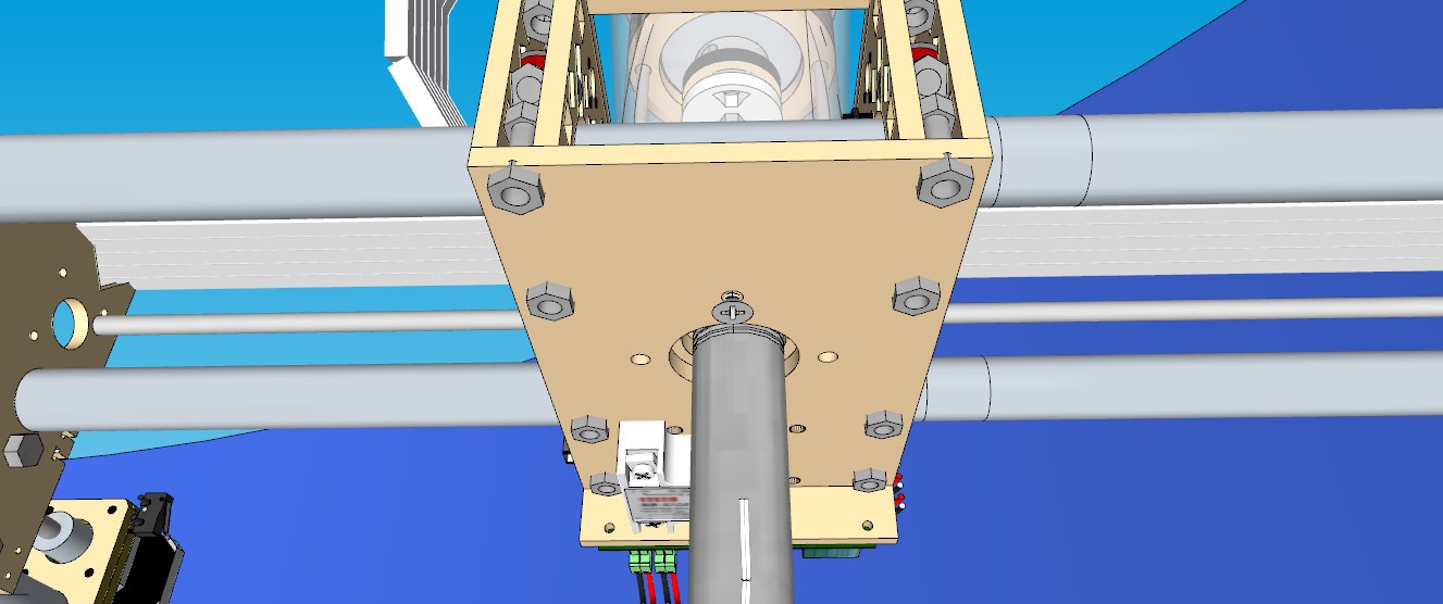
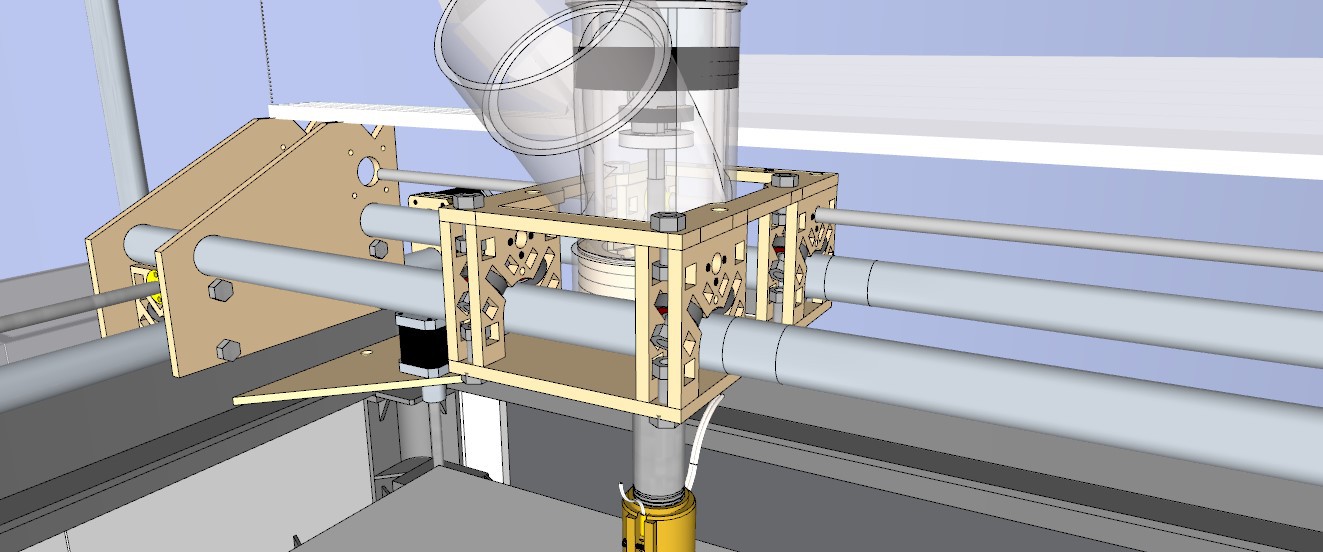
27. Place the assembled extruder onto the X-carriage, resting it on the X1 plate.
![]()
28. Lay down a sheet of 10mm coroplast on top of the plastic bed, and use small clips or screws to keep it in place.
![]()
29. On top of that, tape down a thin steel plate with packing tape. The packing tape helps the plastic adhere to the bed.
You're almost there!
-
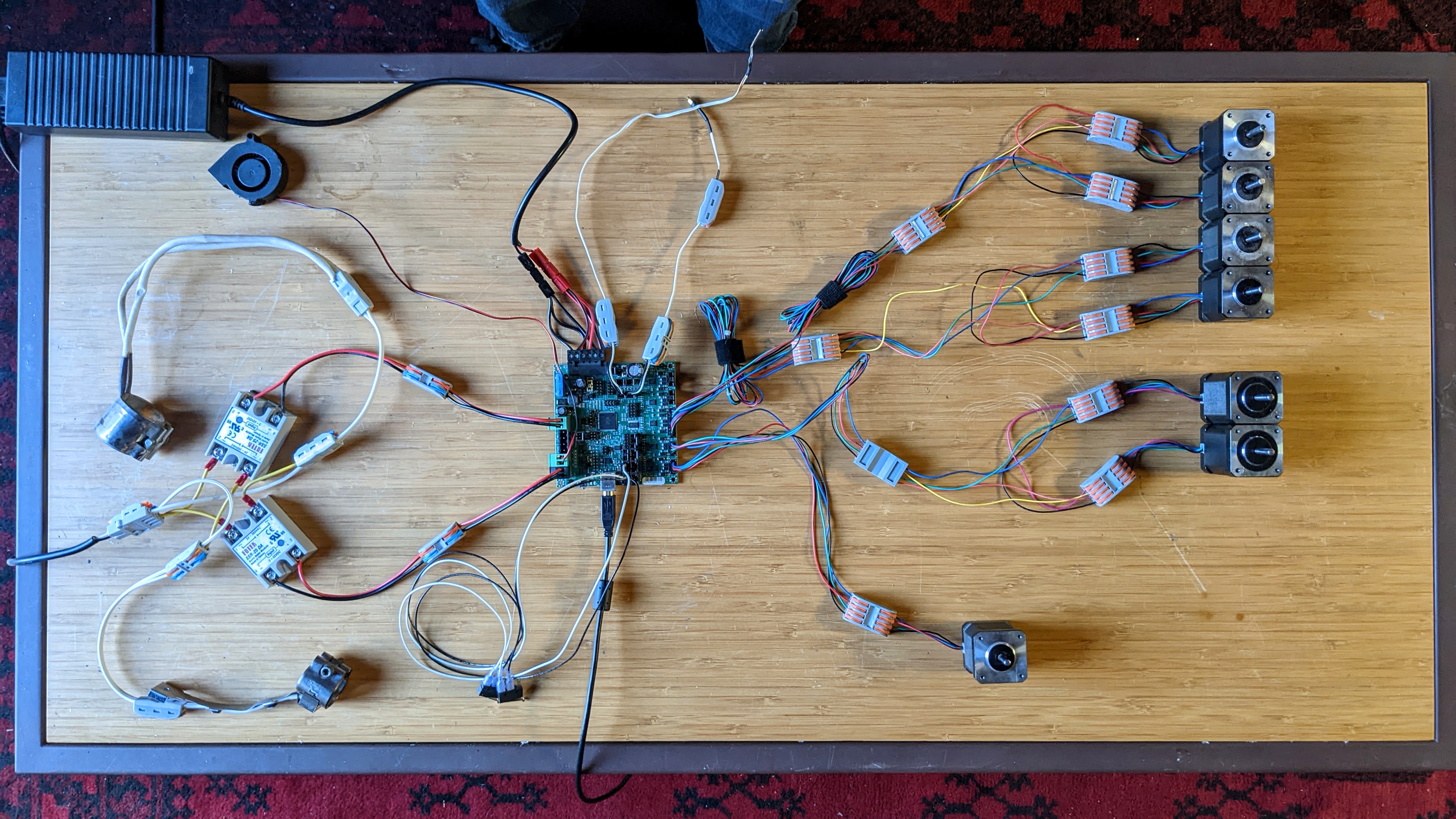
7Connect your Wires
![]()
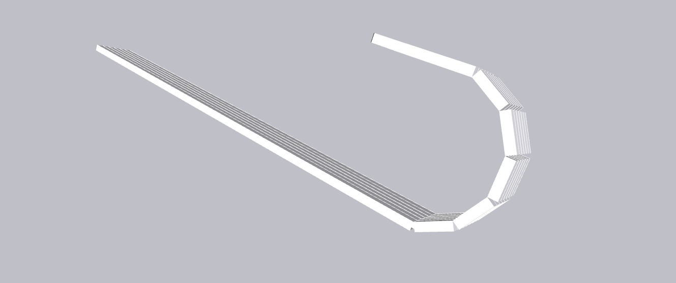
1. Make the cable guide. Cut a 6-flute section out the 36" 10mm Corex sheet, and then make scores (not cuts) at 1" intervals, starting at one side, and moving inward 18". Use a razor blade and straight edge to make scores perpendicular to the flutes at 1" intervals, then use a blade or "coroclaw" tool to make scores alone the flutes on one side to push the cables in. You can do this on either side, but I like to do it on the side opposite the other scores.
![]()
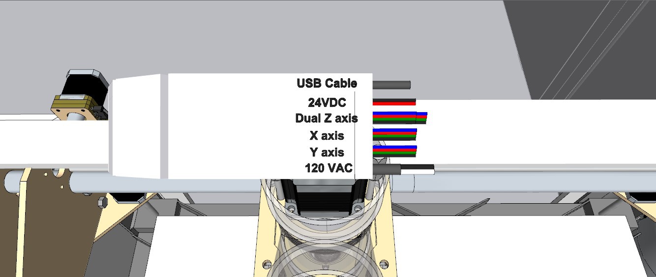
2. Run cables through the guide. Start with 6' lengths and then shorten as necessary- You can run one wire through each flute. There should be 3x 4-wire Black-Green-Red-Blue stepper wires (2 for Z, one for X, and one for Y), 1 x 6' extension cord, one 6' x 18ga Red/Black DC cable, and one 6' right-angle USB-B to USB-A cable.
![]()
Cut off the header leads from all the Z, Y, and X stepper motors, 6" from the end. Maybe cut of them a little long to reach the Extruder with just one connector, measure that one before you cut. For the rest, 6" is fine.
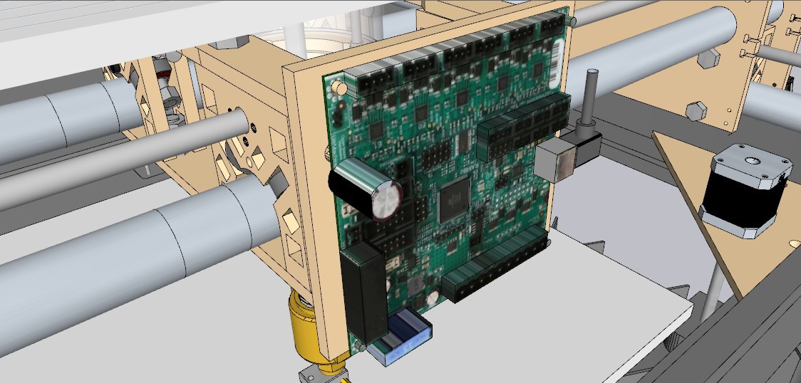
Install the "C1" controller plate to the back of the X carriage assembly using 5/16" counter-sink head (low profile) x 1" bolts. Connect the controller to the plate with M3 15mm bolts using nuts as standoffs if needed. Make sure the control board isn't in contact with the metal bolts, or put tape over them to be safe.
![]()
3. Attach E motor to E0 port - The Extruder motor doesn't come with it's own 4-pin header, just bare wires. You can use one of the headers that you will cut off of one of the Z-motors, since you'll have 6 of them but only need 3 after putting the Z and Y motors in series. Use a 4-position lever lock connector to connect the header cables to the extruder cables - Black to Black, Green to Green, Red to Red, Blue to Bule. If you need to, you can use two connectors and an extra length of wire, but it's better if you can do it just one. More connections means more chances for bad connections, and each connector has 8 connections.
These lever lock connectors work really well, especially for prototyping, and I haven't needed to replace them yet. It was important to me that this project involve ZERO soldering, since soldering a million tiny wires and crimping on headers by hand was by far the worst part of my whole first build, and it seems to me to be high barrier to entry.
If you LOVE soldering and heat shrinking tons of tiny wires, be my guest, it probably would make a stronger connection and it is a bit cheaper, but if you don't, just use the lever locks.
![]()
4. Attach Tip Heater to Heat 0 port
![]()
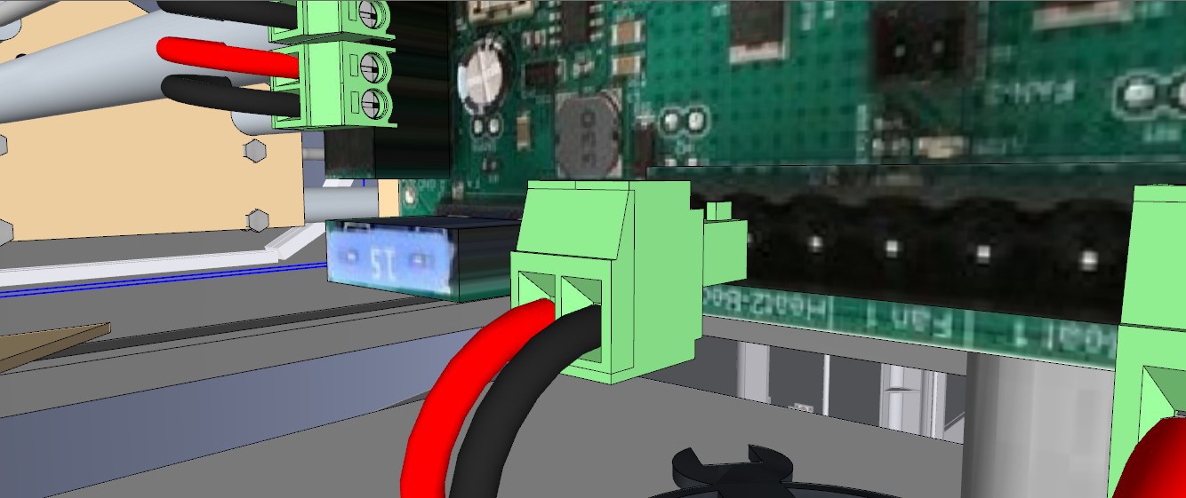
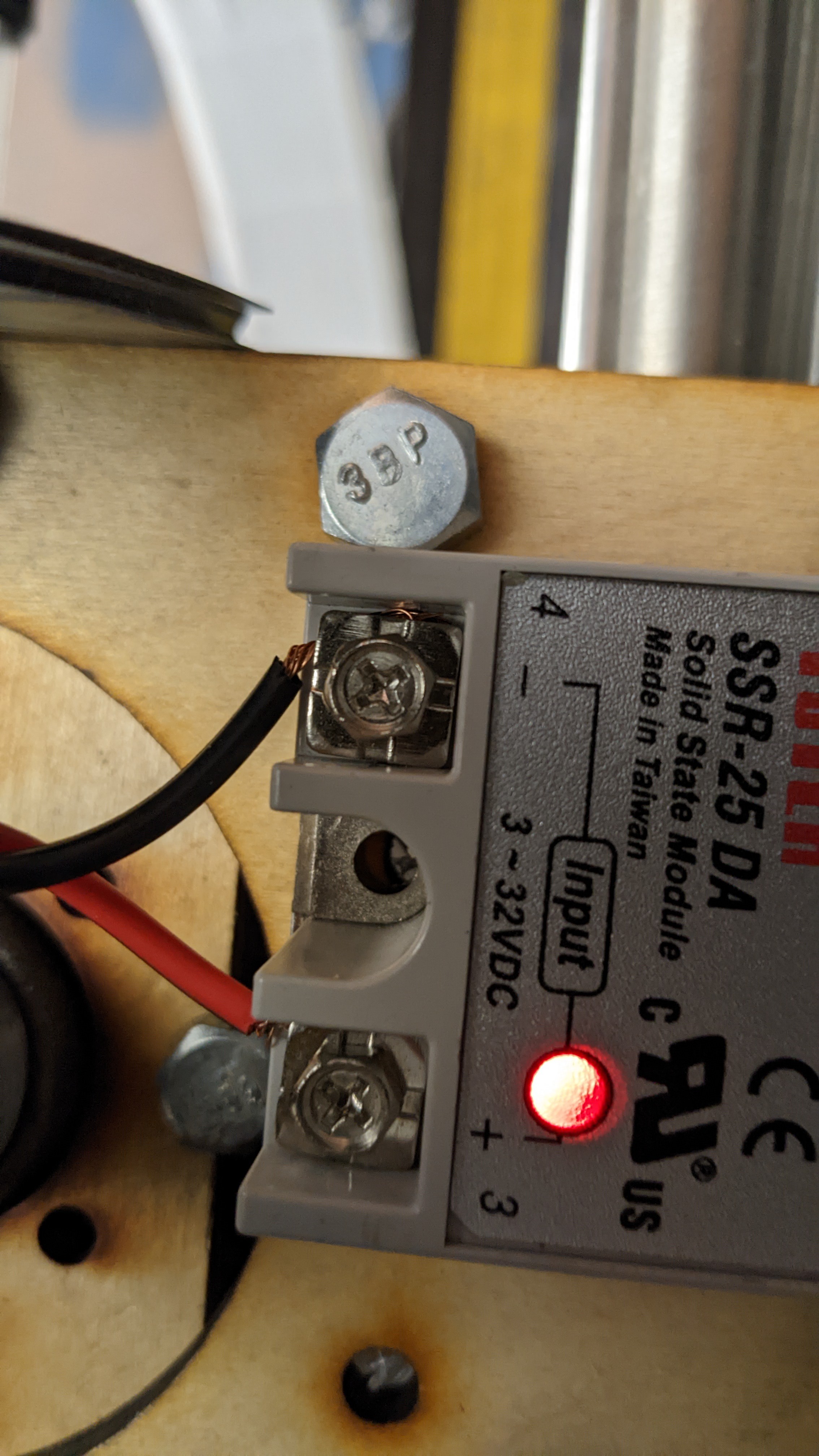
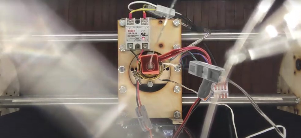
5. Attach DC side of SSR to Heated Bed port.
![]()
Connect the other side to of heated bed output to the corresponding DC terminals on the SSR. It should look like this: Note that there is a DC side and an AC side, make sure you get them right. Also note that some SSRs that look almost identical are meant for switching DC with DC, so check the specs on them, or just follow the link in the BOM.
![]()
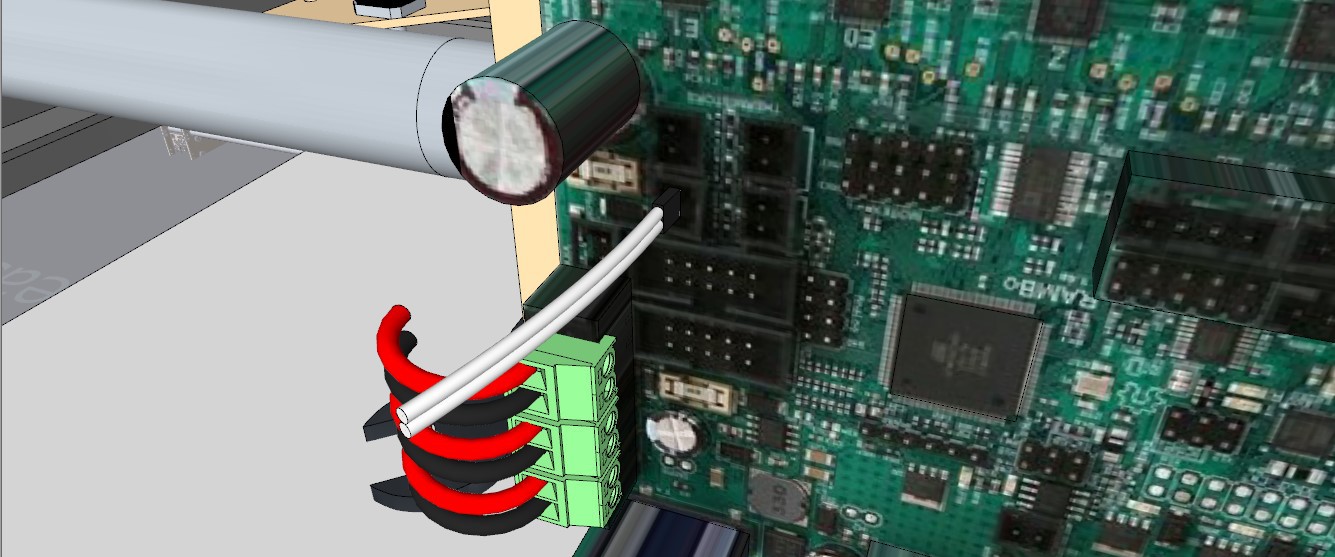
6. Attach the 24VDC 18ga Black-and-Red wire (I'm using red and blue in this picture) from the cable guide to 3-1 lever lock connector, and connect to the output wires to the 3x molex power input connector (included with the RAMBo board)
This splits the 24VDC into 3 outputs, so that you don't have to run 3 cables. The RAMBo board has independent power inputs, that you can use different voltages for. One is for the logic, one is for the motors, and one is for the heaters. In this case, all of them are running 24VDC, so we just split them into 3 lines so we can use the provided connector.
![]()
7. Attach the "Bed" Thermistor
![]()
8. Attach the Tip Thermistor
![]()
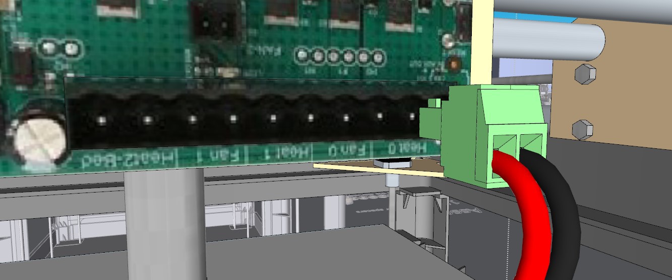
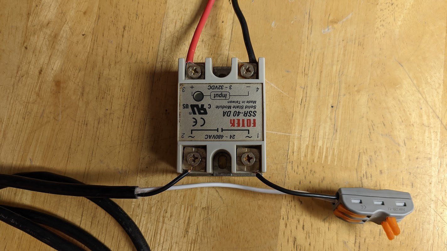
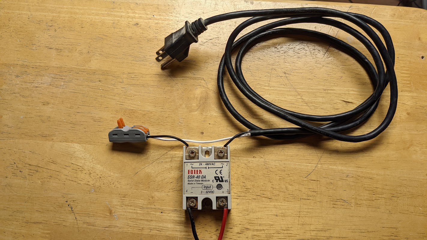
9. Cut the end off your extension cord, and strip back the wires by 6". Cut the black wire, and connect it to the AC side of the SSR, like in the photo. The two open terminals on the lever connector will connect to the 2 wires coming out of the band heater. It doesn't matter which way you connect them.
![]()
Use a 2-position lever connector to connect the AC wires back together. Note how the SSR is interrupting the black AC "Line" cable. The SSR is just a like a light switch, it turns the AC power on and off, whenever a DC voltage is applied by the control board.
I have mentioned this elsewhere, but this seems like a good time to mention that one of the major "hacks" I made to get this thing to work was to just use the "heated bed" output to switch an AC band heater on and off, using the SSR, which lets me get a lot more heat into the extruder. It acts just like the "barrel heater" on the original Precious Plastic extruder I built in 2017, it's just controlled by the 3D printer software now.
So when I say "Turn on the heated bed" or when you see the control software reading the "bed temperature" what that really means in Trash Printer terms is the barrel pre-heater, not the actual bed. In the future, adding a heated bet probably couldn't hurt, and this is probably an inelegant solution, but I didn't know how to do it any better when I built it this way, and I still don't, and this seems to work pretty great.
But if you figure out a better way to do that, PLEASE share it on the github. In the meantime, just do it this way, it works.
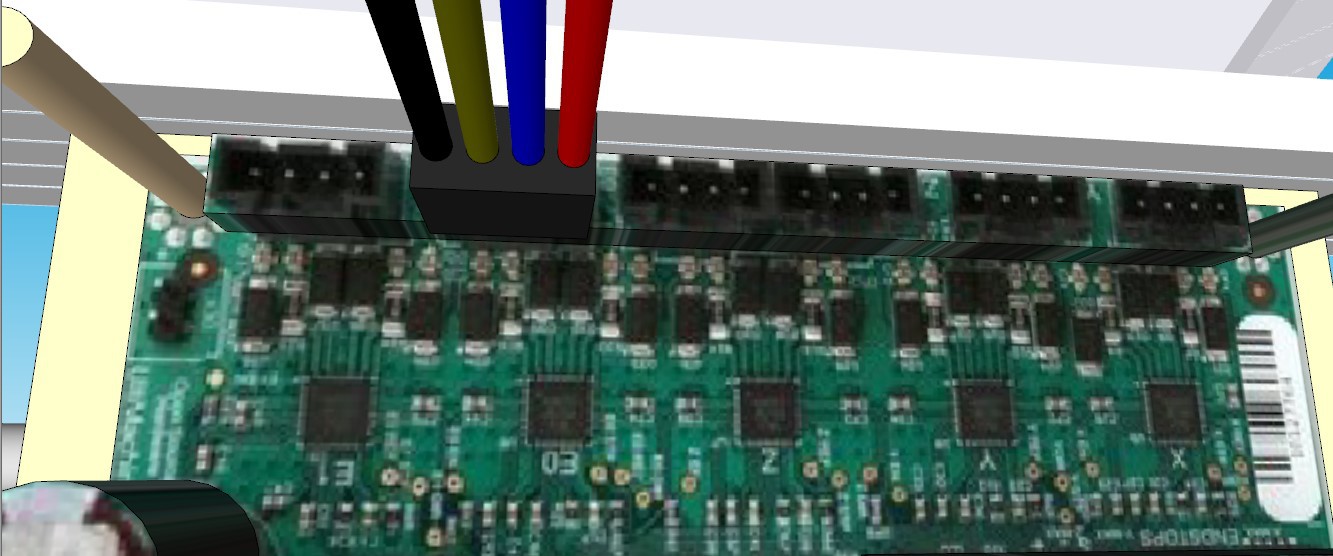
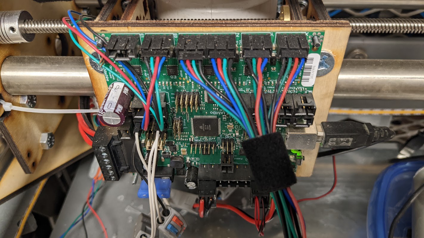
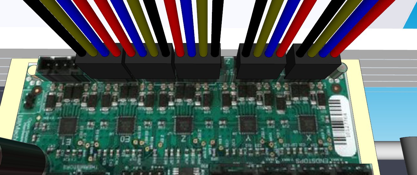
11. Attach one of the 4-pin headers to the X port, one to the Y port, and two to the dual Z ports.
Note here that the 2 dual Z-motor wires are oriented the opposite direction. This is just because I had to flip them during calibration and haven't got a chance to fix it in a more elegant way yet. This way works with how I currently have the rest of the wiring, so just do it this way for now unless it bugs you.
![]()
![]()
12. Use four 4-position lever-lock connectors to connect the X, Y, and dual Z header wires from the control board to the 4 runs of stepper cable that you put into the cable harness. Black to Black, Green to Green, Red to Red, Blue to Blue.
![]()
![]()
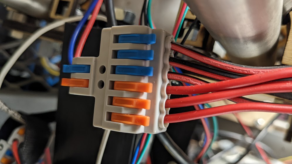
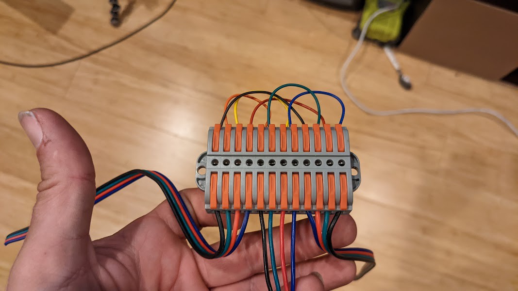
13. Now connect the Y motors in series. Take the Y motor wire from the wiring harness, and connect it to the middle 4 positions of a 12-position connector, Black, Green, Red Blue, from left to right.
![]()
Connecting steppers in series is a little less straightforward than connecting them in parallel, but it makes them run smoother and quieter. These 12-position connectors make it easy - you don't really need to understand what's happening electrically - I sure don't. The colors of the top row don't really matter, what matters is the position they connect to.
The bottom row is Stepper 1 on the left, Stepper 2 on the right (note the order is reversed relative to the other 2) and the middle is the single input wire that will connect to the control board.
Here is a cheat-sheet for connecting the series wires:
From left to right, imagine that each position is numbered 1-12 on the top and bottom row. The bottom row has 3 sets of 4 cables going in, in this order:
- Black
- Green
- Red
- Blue
- Black
- Green
- Red
- Blue
- Blue
- Red
- Green
- Black
Note that the right-hand stepper motor wires are reversed relative to the other two. If you connect this one backwards, one stepper will go one direction and the other will go the other way, and it’s just not what you want.
Now, without rotating the the connector, the top row wires connect like this:
1 connects to 9
2 connects to 5
3 connects to 7
4 connects to 11
6 connects to 10
8 connects to 12
The color scheme is the one that comes with the V1engineering series wiring kits, so that’s the color scheme I used. Wire color doesn’t matter in this case, only the connections matter. You can use any wire you have, but you can use this color scheme if you want. It might be easier to just use a single color.
Connect the single output wire for the two Y motors in series to the Y wire coming out of the wire guide.
14. Now do the same for the Z steppers, connecting the left two motors in series, and the right two motors in series. Take the single output wire from each Z series connector, and connect them to the dual Z wires coming out of the wiring harness, using 2x 4-position lever-lock connectors, and connecting black to black, green to green, red to red, and blue to blue.
15. Use a 2 position lever lock connector to connect the DC wire from the cable guide to the DC side of the 24V power supply.
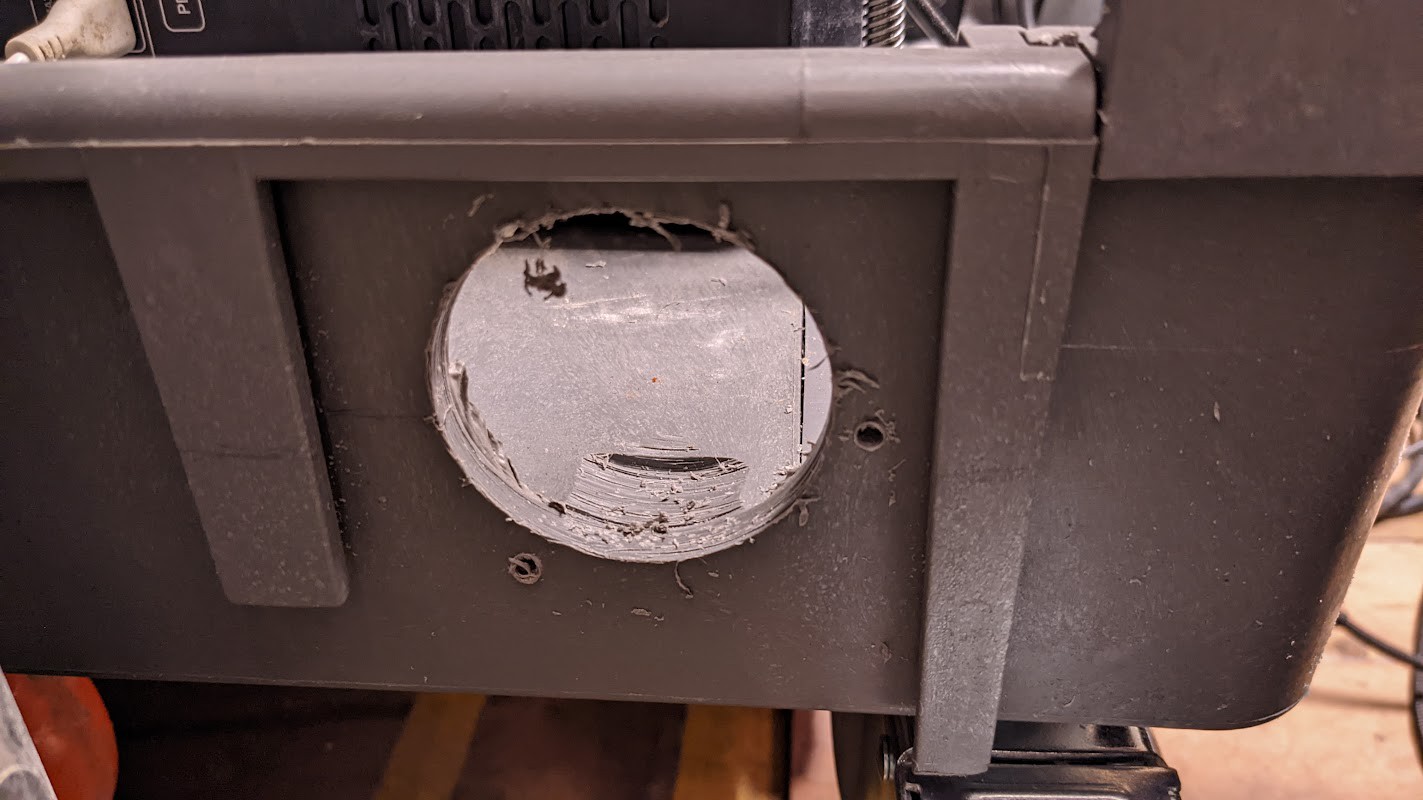
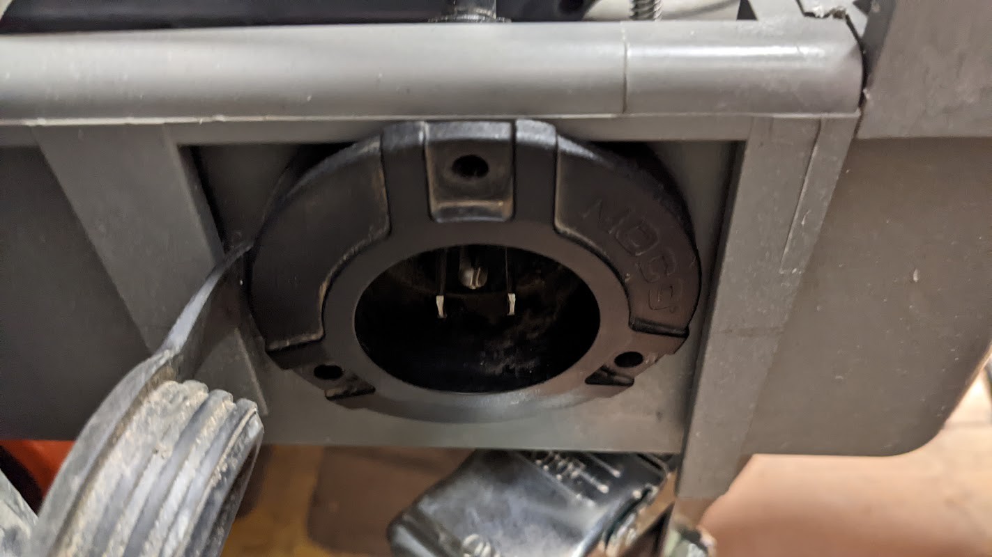
16. Cut a hole for your 120VAC input and install a pass through power inlet (this is optional, but makes it nice and clean.)
![]()
![]()
I probably could have done that better, but you get the idea.
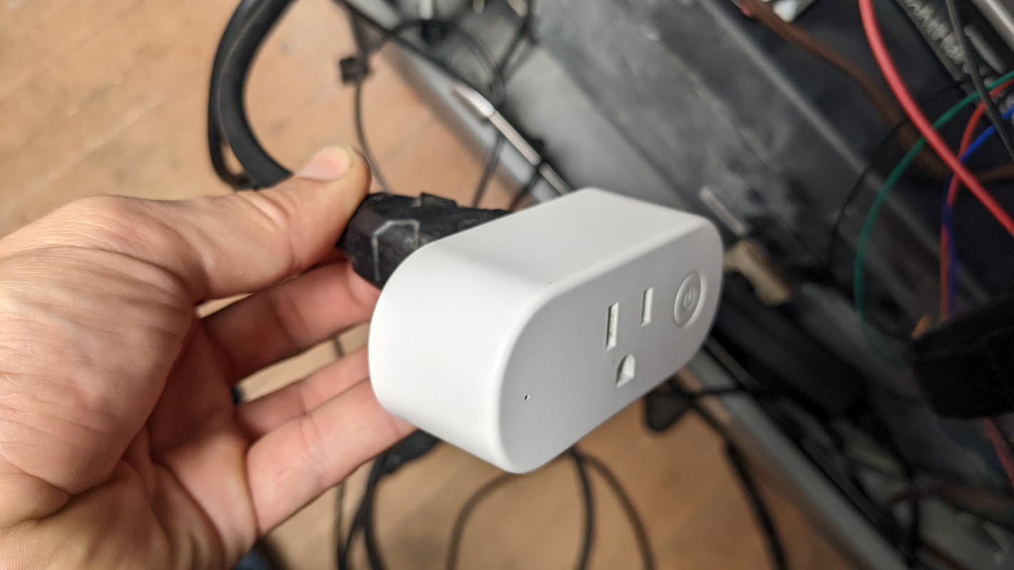
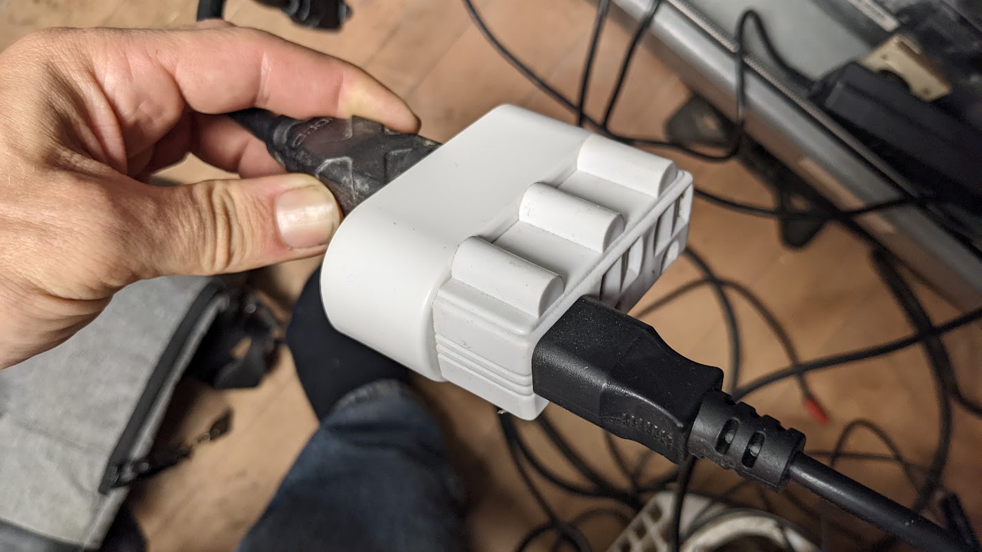
18. Attach Smart Plug to the other side of the input plug - This is optional but it lets you monitor your energy consumption and calculate your watt-hours per gram, and also has build-in short-circuit/overcurrent protection. I'm using a Shelley brand smart plug because it integrates easily with Home Assistant, but you can just use their app to monitor energy consumption.
![]()
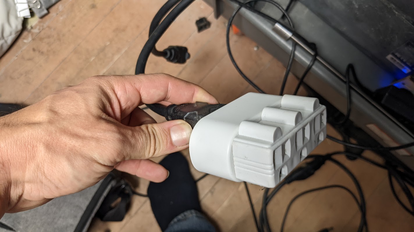
19. Plug in a 3-1 AC outlet to the smart plug, so that you can plug in the 24V power supply, heater plug, and optionally a 5-volt power supply to power the USB lights and optionally a Raspberry Pi for wireless printing, while monitoring the total power consumption of the whole printer.
![]()
20. Plug in the AC side of the 24VDC power supply to one of the 3 outlets. Nothing will happen if you accidently do, but don't plug in the heater just yet.
![]()
21. Check all your connections, make sure your DC polarity is correct. Then plug the printer into a wall outlet with an extension cord. The lights on your control board should light up!
Oh my trash, you are getting so close!
-
8Program your Board
I'm a pretty mechanically inclined person, not a "code person". So, briefly, here's an overview on how 3D printers work, assuming you don't know anything about 3D printers, like I didn't. If you do know, you can probably skip this part.
Motors and Sensors
The Printer is really just a a bunch of heaters, motors, and sensors. These components are all connected to the Control Board by wires.
Wires
The components connect together with wires. Managing these wires is a big part of building a 3D printer. The type of electricity the wires carry dictates the kind of wire you use. Use the wire I recommend, unless you know what you're doing.
Control Board
The control board is based around an Arduino, which is an open-source re-programmable microcontroller - basically a very small low-power computer. The RAMBO 1.4 board I'm using also includes special components specific to 3D printing, like heater and motor drivers, that let the Arduino control the heaters and motors directly without additional boards.
Firmware
The Arduino IDE is a program that let's you upload code to the Control Board. The code that I'm using is called Marlin, an open-source control firmware designed for 3D printers. This lets the Control Board interpret signals from the computer and turn them into objects.
Control Software
The control board plugs into a computer or a Raspberry Pi (another open source mini-computer) using a USB cable, and allows you to send prints and commands to the control board. The control software I'm using is called Repetier-Host.
Slicer
A Slicer Program is a program that slices a 3D model into a set of layers, based on your printers' specifications. It outputs a file in G-Code, which is a language that tells the control board how to move the motors and heat the heaters, in order to print an object. How you slice a model is very important for getting good results. The Slicer program I'm using is aptly named "Slic3r" and it is built into Repetier-Host. You shouldn't need to download and install it separately.
Putting it all together.
OK, make sense? This was the hardest part for me, and I hope I can make it easier for you. If you're feeling good so far, let's keep going.
1. Power up your board. You won't be able to program the controller by USB power alone. It MUST be connected to the 24VDC power supply.
2. Connect the USB cable to your computer.
3. Download Arduino IDE, and install.
4. Open the "Marlin 2 for Trash Printer V3 9-28-22.ino" file. Make sure that you DO NOT rename this folder when you extract it. Arduino will expect the folder this file is in to also contain other files, the configuration.h, the configuration_adv.h and the version.h file, and it expects these to be inside a folder with the EXACT same name as the .ino file. If you open the file, and you do not see tabs for the files, you need to check this.
![]()
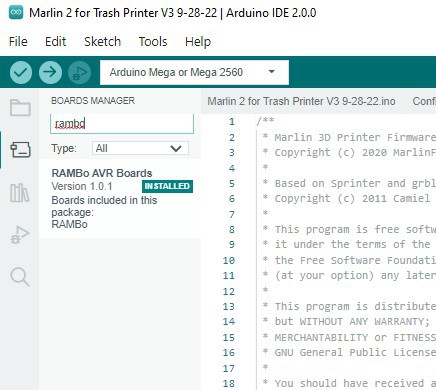
5. Go to the boards manager, and search for "Rambo". Install the RAMBO board option that comes up.
![]()
Mine is already installed, but where it says "Installed" it will say "Install". Click that to install.
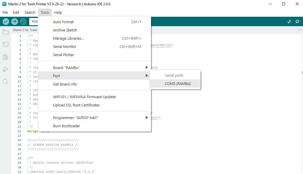
6. Then go to Tools > Board > RAMBo AVR Boards > RAMBo
7. Now go to tools > Ports > COM5 (if you're using a mac, this will look a little different, and the COM number will change. It's usually the only one available)
![]()
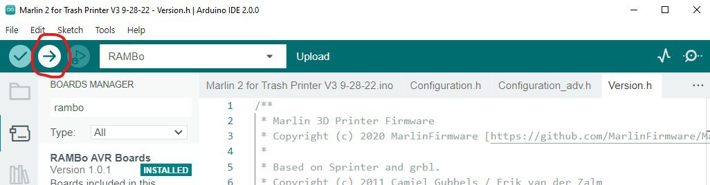
Hit "Verify". The program will check to make sure the code is all good. This can take several minutes.
Once the code has compiled, hit Upload. This will also take several minutes. If you watch the lights on the control board, and the flash or blink when you hit upload, that's a good sign you've got the right port.
![]()
If the code compiles and uploads, then you're ready to move onto the next step!
-
9Calibrate and Test your new Trash Printer!
You did it! You're so close! Now it's time to set it up and test it out!
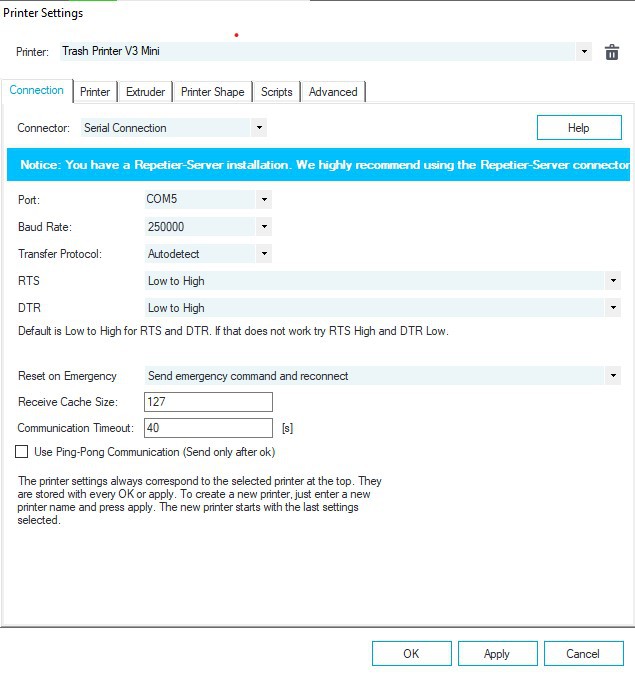
Go to the "Printer Settings" and on the "Connection" tab, make sure these parameters are correct:
![]()
Now go to the Printer tab, and make sure these parameters are all the same:
![]()
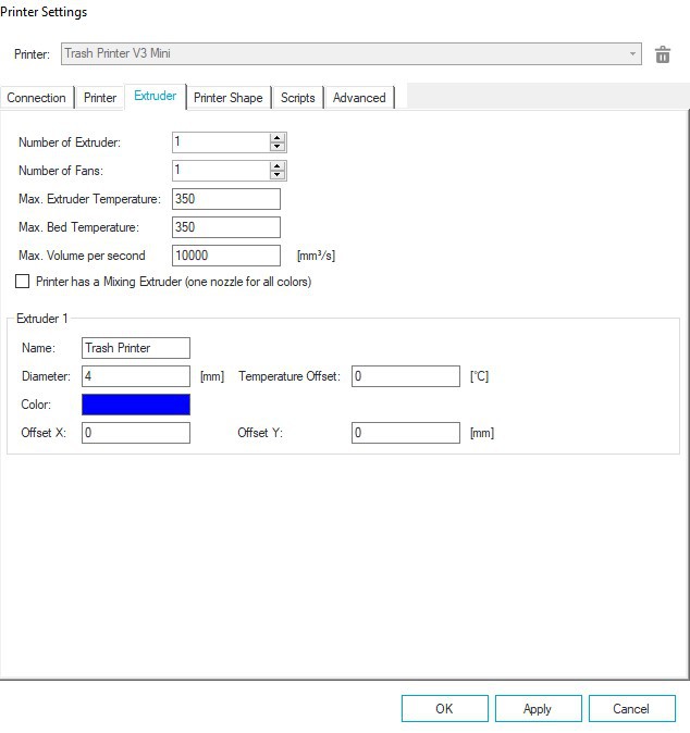
Next, the Extruder tab:
![]()
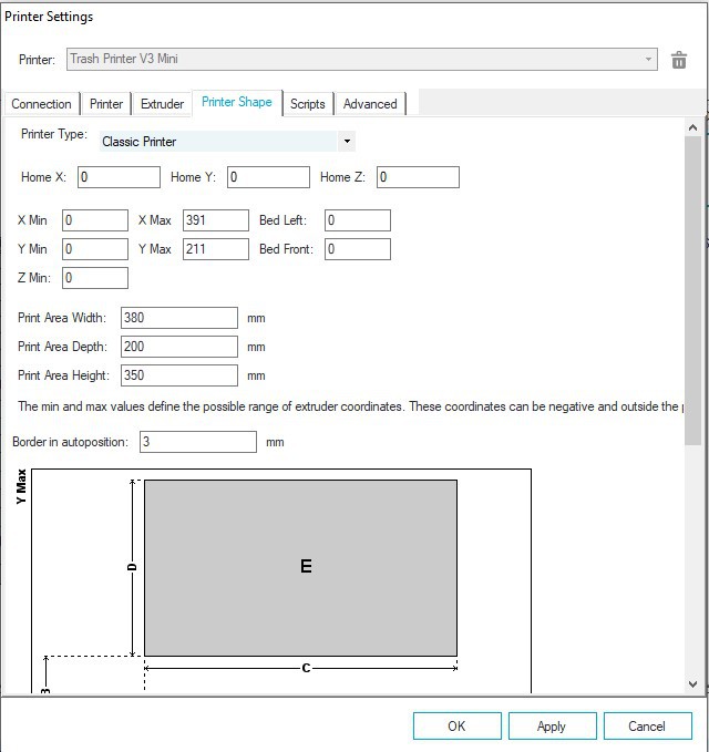
And finally, the "Printer Shape" tab:
![]()
Hit "Apply to save these changes.
Note that these dimensions are for the Trash Printer V3 Mini. If you're building the regular version, you'll want to use larger settings. It's best to actually measure your travel, for now, just use the mini settings.
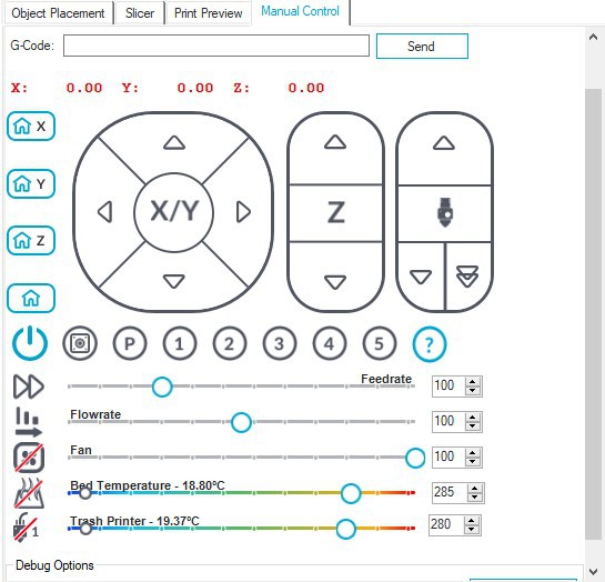
Next, we're going to test to make sure everything is working the way it should.
First, check to make sure your thermistors are working. If you see temperature readings for the extruder and heated bed, that's a good sign.
![]()
Double check your wiring, and when you're ready, click on the exruder icon with the red line through it, to manually turn on the extruder heater. When you do this, you should see the temperature reading rise quite quickly. If the temperature rises when you turn the heater on, you can turn it off again. It's working!
![]()
![]()
Now, we're going to do the same for the Barrel Heater. The Barrel heater uses 120VAC that is switched by the SSR, with a 24VDC signal. Double check your wiring, and don't plug in the heater just yet. When the SSR is "on" a little red light will come on, even if there is no AC power. This lets you test it without power the first time.
![]()
![]()
![]()
Once you've confirmed that the SSR is working, you can plug in the heater, and try it again to confirm that the temperature rises, just like you did for the extruder heater.
Now, we're going to test to see if the motors are working.
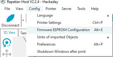
First, go to Config > Firmware EEPROM Configuration
![]()
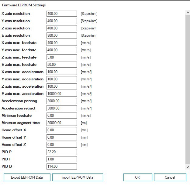
Then, change the settings to match these:
![]()
Hit OK.
Now, manually turn the lead screws a little, to move the head into the center of the work area a little bit. This gives you some wiggle room if your motors are reversed.
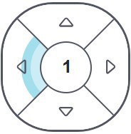
First, test the X axis, making sure you select the "1" option, that stands for 1mm. Click the positive, not the negative number.
![]()
You should hear/see the stepper move 1mm to the left. If you don't, check all your connections. If it's backwards, double check that you are clicking the positive 1 and not the negative 1, and if it's still backwards, flip your connector around at the control board.
Now do the same for the Y. If they move in opposite directions, check your series wiring. If they move the together but the opposite direction, flip the connector at the controller.
Finally, do the same for the Z. The positive number should move the bed down. If it moves it up, check your connections.
Finally, it's time to feed your printer. You can't test the extruder motor until the extruder is up to melt temperature, to prevent you from breaking it. So now, feed some shredded plastic into the hopper, enough to cover the whole auger, and turn on both your heaters.
I like to start low, around 150C, and let the heaters settle there before going to full temperature. 3D printers use "PID" (Proportional Integral Derivative) heat control, and it learns to control the heaters very precisely, but until it learns what the heaters do, it can cause wild temperature swings. It's kind of like driving a car at full speed and then jamming on the brakes at when you get to a stop sign - you skid waaaaaay past the sign. So for the first go, set the temperature to about half, and let the temperatures settle.
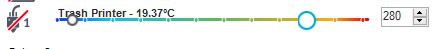
Once they've stabilized, set the bed temperature to 230C, and the Extruder temperature to 275C.
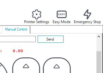
Once up to temperature, try turning the extruder motor by hitting this button:
![]()
The extruder motor should move, and it should move so that the auger pushes material downward. If it pulls the material up, reverse the connection. If it stalls, check the alignment of everything, and make sure you're using a 15:1 NEMA23, and that you changed and saved your firmware EEPROM settings, particularly the E axis resolution, which should be set to 800 to start (you can change this later)
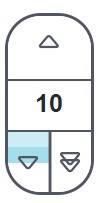
Now you can manually extrude. Once you know the motor is moving the right direction and not stalling, you can move in 100mm intervals at a time. You may need to keep clicking this button for several minutes, until plastic starts moving down the barrel and melting.
![]()
You're basically there!
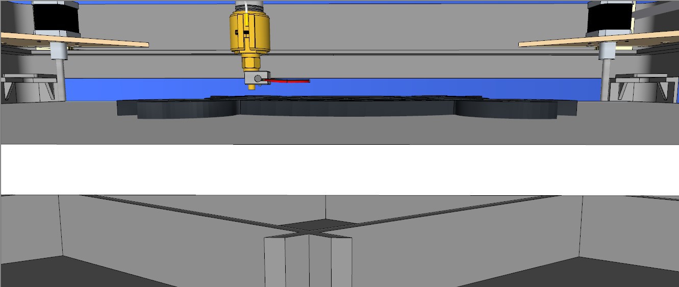
Move the printer head to the back right corner of the bed, and raise the Z bed to be about 1mm from the nozzle.
Turn off the heaters, and reset the printer position by disconnecting the printer, and then reconnection. Resetting the printer makes the position it's in reset at as 0,0,0, the home position.
![]()
-
10Print your Trash!
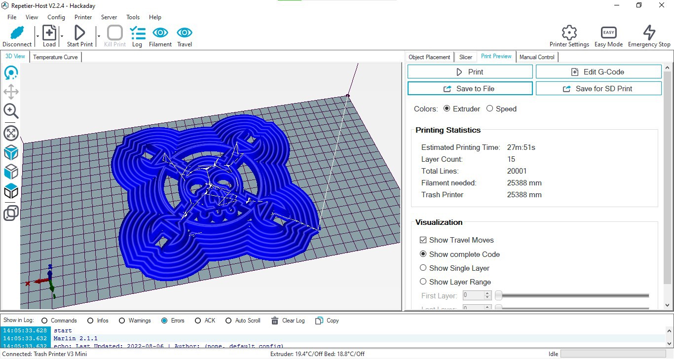
OK, so now it's time to make your first trash print! For your first print, try starting with the raw gcode file from the Files section, instead of slicing something. If you're machine has the same specs as mine, you should get similar results.
Go to File > Load, and load the Hackaday.gcode file from the files section. It should look like this:
![]()
Preheat the bed and extruder, and go over to the temperature curve tab to watch them level out:
![]()
I like to let the heaters warm up for about 10 minutes. Once they're up to temp and leveled out, you can hit Print!
This is a good time to mention that if your printer ever moves the wrong way, you should be ready to hit the "Emergency Stop" button in the top right corner. Be ready to hit this, especially on your first print.
![]()
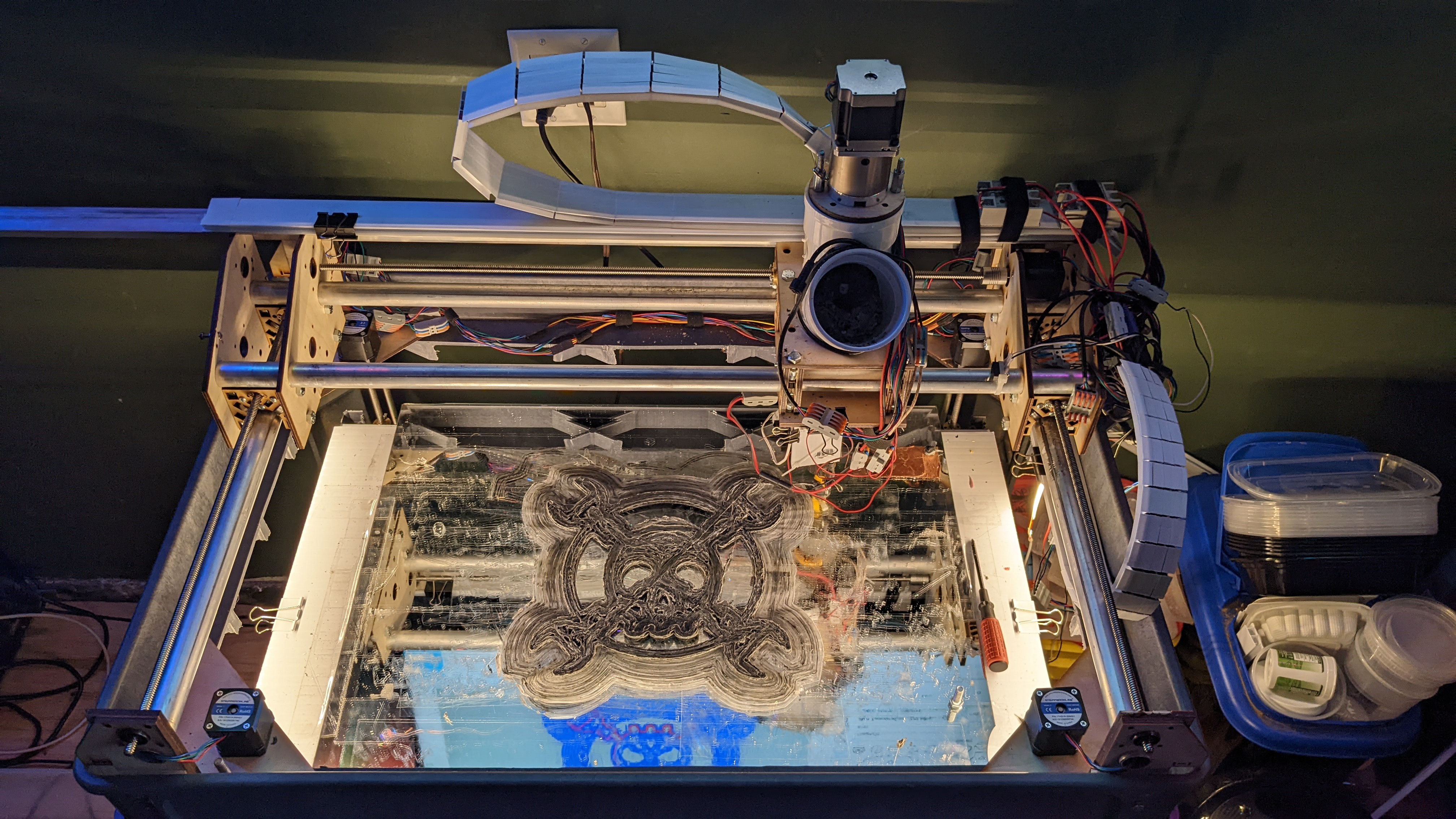
If everything is working right, you should get something like this!
![]()
The Trash Printer - Version 3
An open-source, low-cost, large-format 3D printer that can print directly from shredded plastic trash instead of filament


Discussions
Become a Hackaday.io Member
Create an account to leave a comment. Already have an account? Log In.