 Jerry Isdale
MIDI control boxes are a popular product, although they can be expensive. We wanted to build one with a custom box, and perhaps reconfigure. We found two Adafruit Learn articles describing something close using the rather cool CircuitPythonsystem:
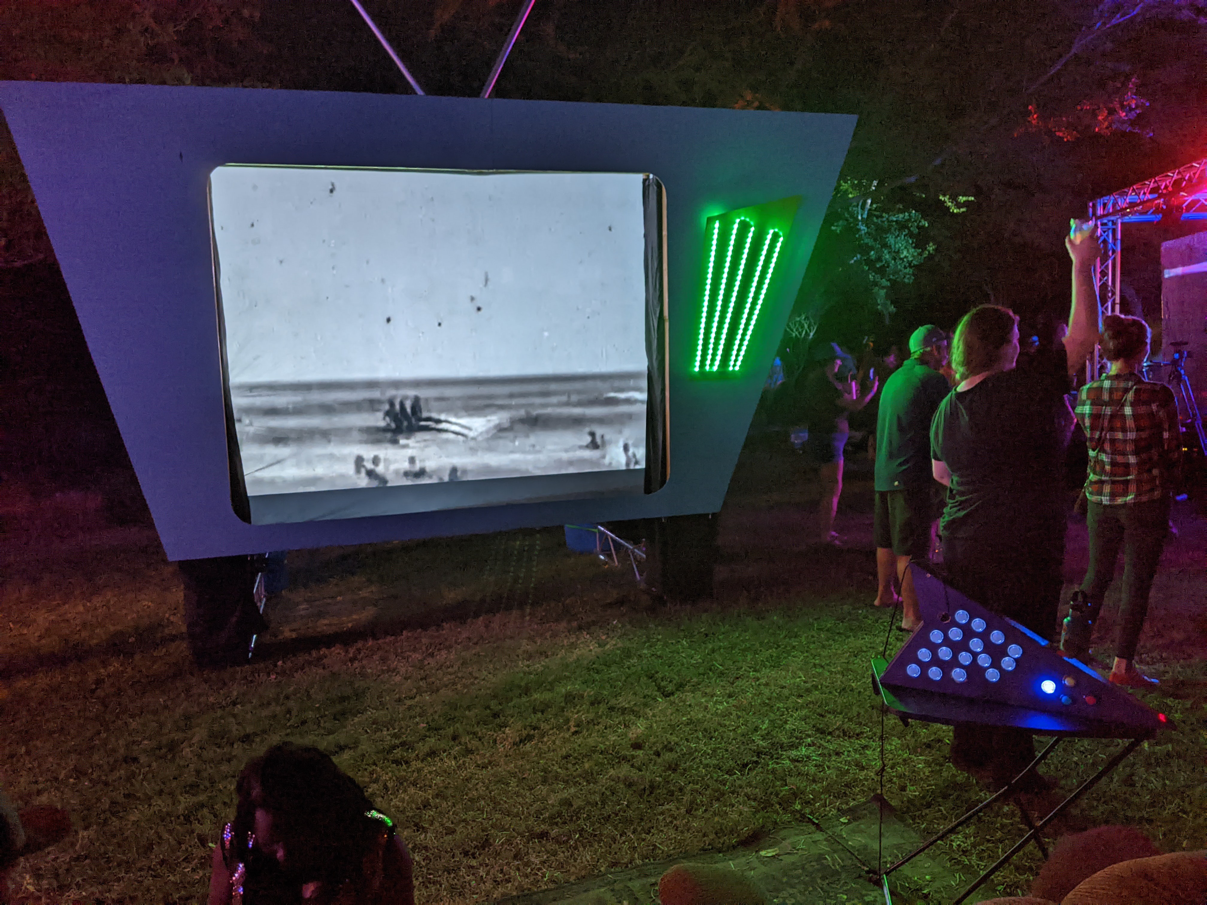
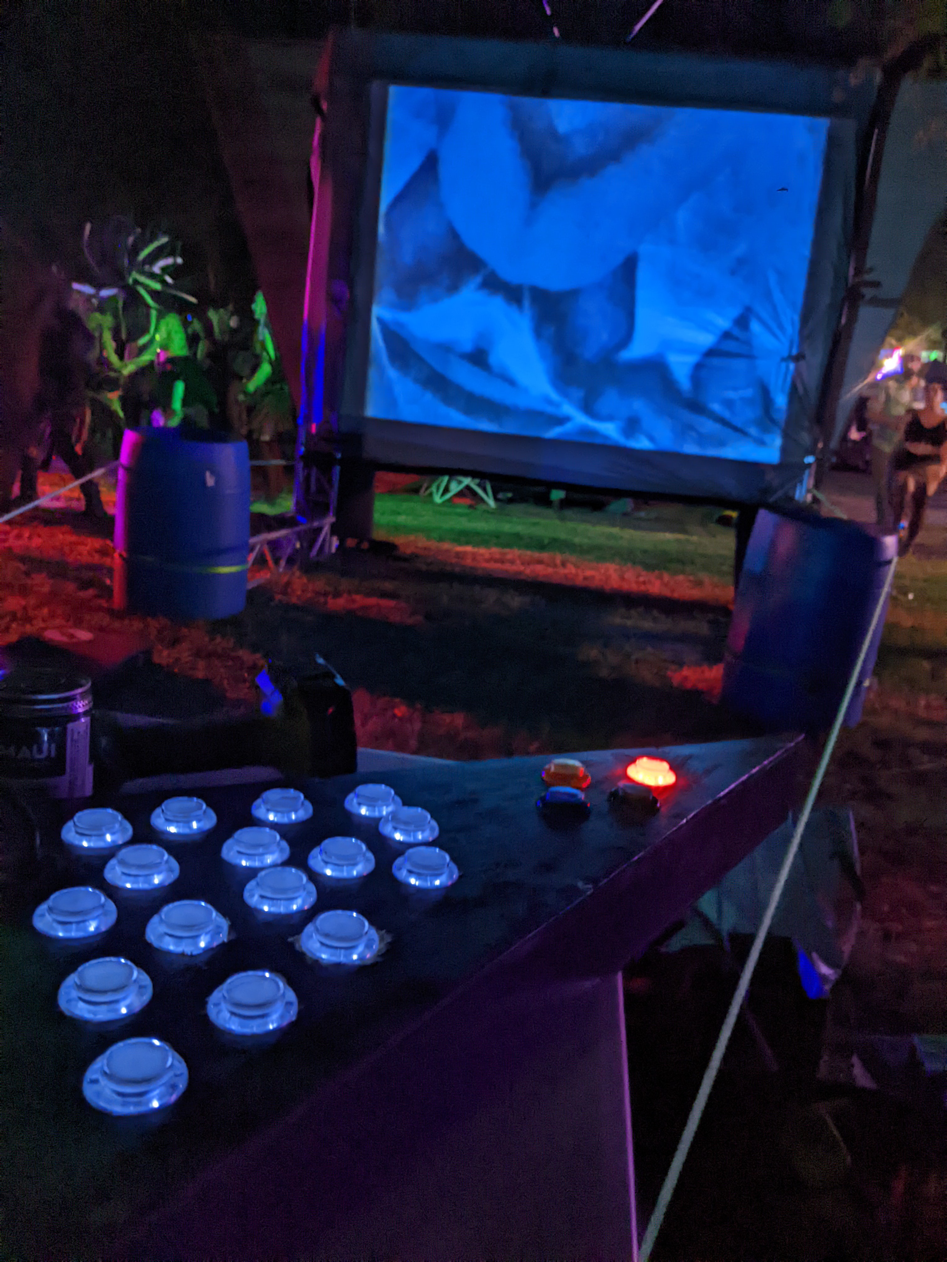
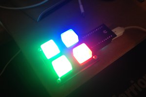
- Raspberry Pi Pico and LED Arcade Button MIDI Controller : a 4x4 array of buttons with fancy little screen to change their notes buttons and leds are directly connected to the rPi Pico
- Adafruit LED Arcade Button 1x4 STEMMA QT uses the Adafruit LED Arcade Button 1x4 STEMMA QT to handle buttons by i2c. This is much cleaner approach but the project doesn't do the midi or fadeIn/Out led effects
Setup of the Pico for CircuitPython is well covered in Getting Started with Raspberry Pi Pico and CircuitPython.
I use several different editors (Visual Studio Code, PyCharm, etc) but for this CircuitPython project, I found the Mu editor worked best as it has a console window to connect with the device. I did have some issues with the Pico reboot/autoload but there is a quick hack around that in code.
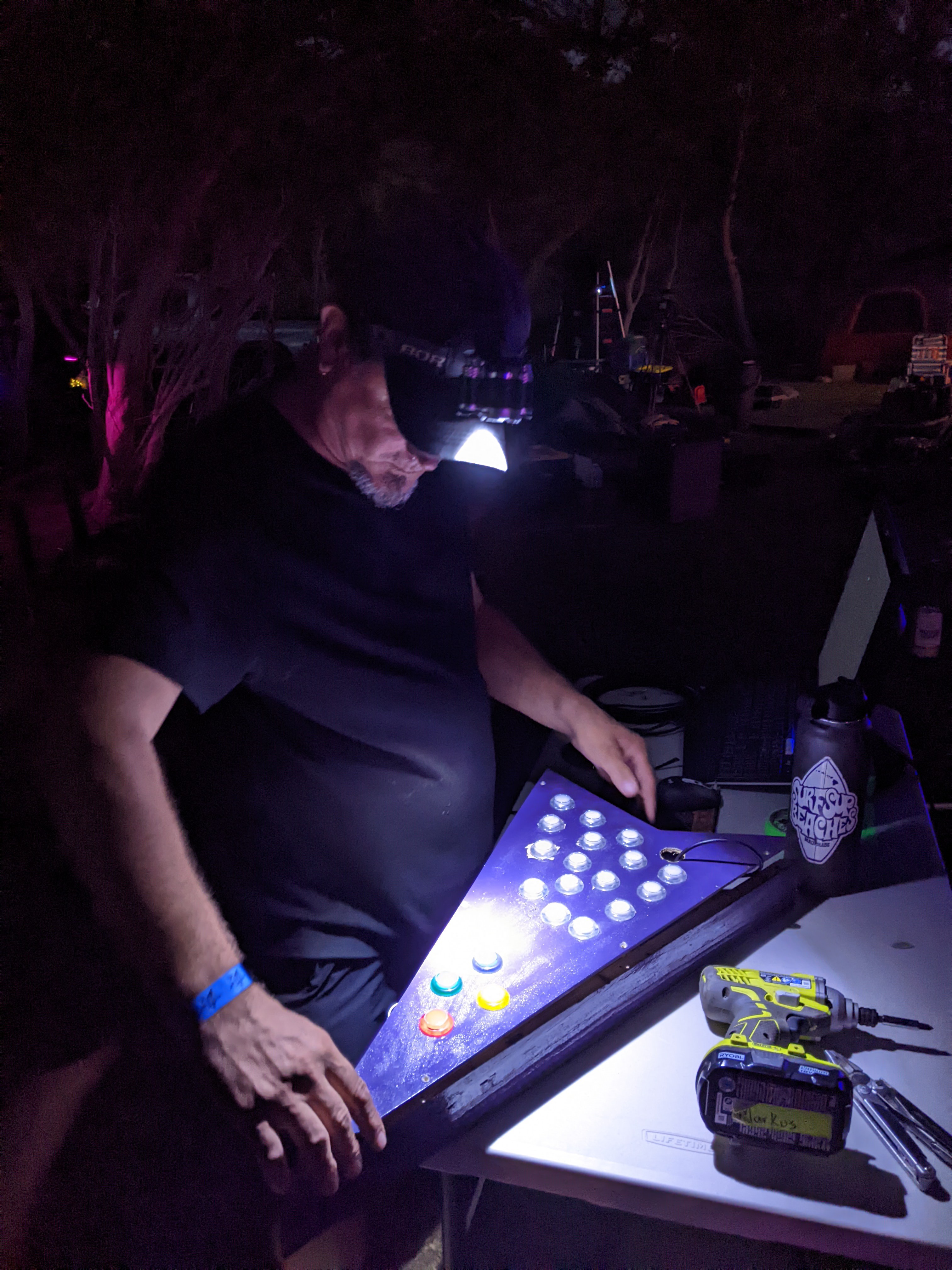
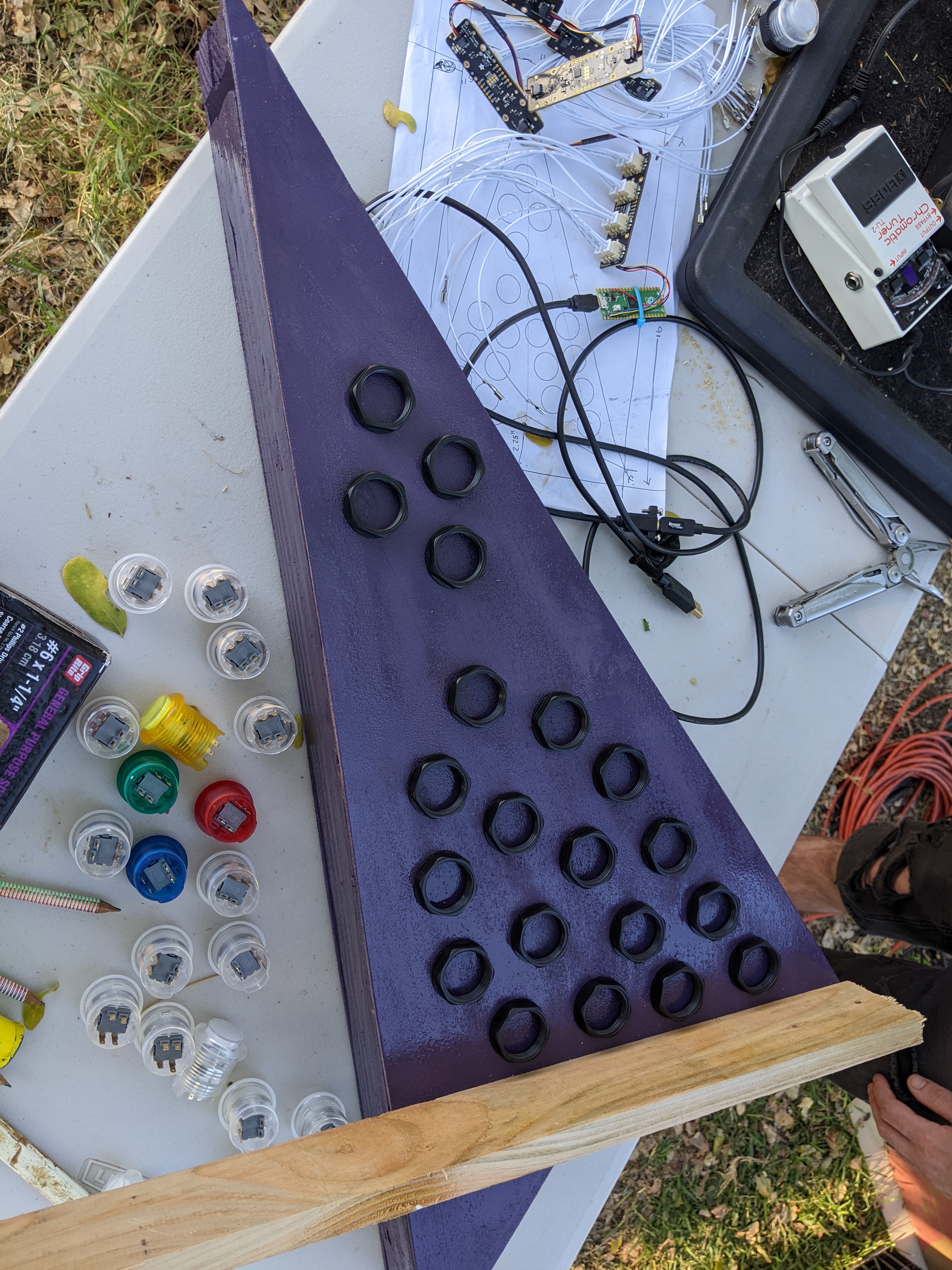
Both the Learn.Adafruit projects use the Arcade Buttons which have a plain white led. Adafruit does offers different color options for the plastic housing The Adafruit documentation doesn't provide a reference as to which are pins are for switch vs led: (yes need to add pic here)
- switch is on staggered pins
- led +/- is on in-line pins, +- with arrows point to that side
It is possible to take the buttons apart and insert color gels or other labels if you want. It would be really nice if there were some nice Arcade Buttons with neopixel leds, but that is still a hack left to the adventurous. I did that for another project which i might document here someday.
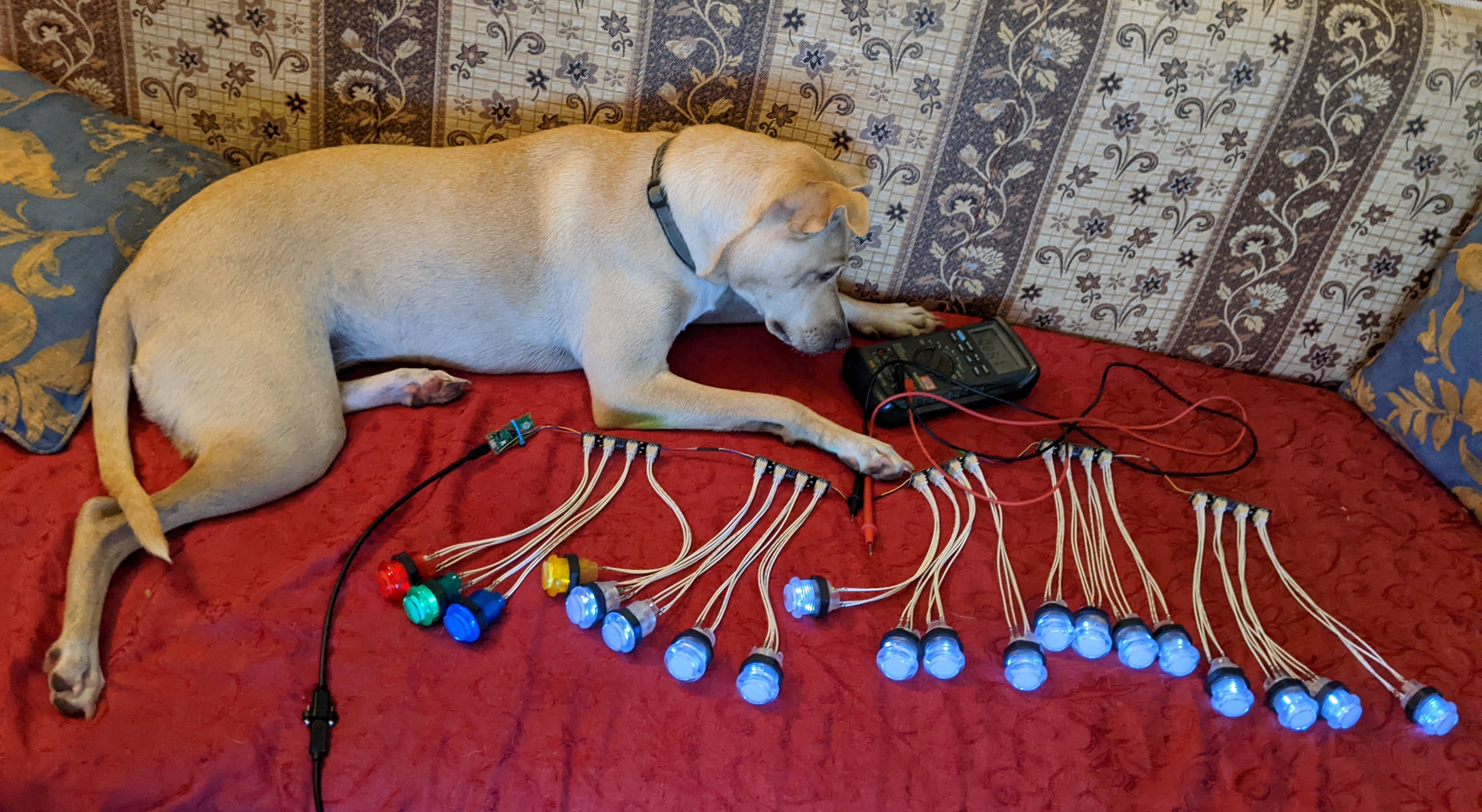
The i2c board makes it MUCH easier to build a 4xN button box.
Using I2C with jumper locations, up to 16 boards can be supported, for total of 64 buttons. That is a LOT more than you could directly wire. Adafruit's Arcade Button Quick Connect Wires eliminate soldering for buttons and leds. This reduces total number of solder connections to the 4 i2c lines to the Pico, assuming you use a JST-PH 4 wire connection. Adafruit offers a nice JST SH 4-pin to Male Headers Cable that makes it easy. You could use regular hookup wire from the Pico to the side holes on the i2c board, or cut one of the various JST SH cables.
personal vetch: there are many different JST connector types with different spacing. Be sure to get SH cables for these boards
The Adafruit code examples are written to support multiple processor boards. Some use board.i2c others use busio.I2C. Neither example mentions the rPi Pico. The Pico uses busio. I eliminated the board.i2c to reduce confusion.
A USB microB panel mount will be used to bring the USB/power connector outside the box.
Code is available on my GitHub Project
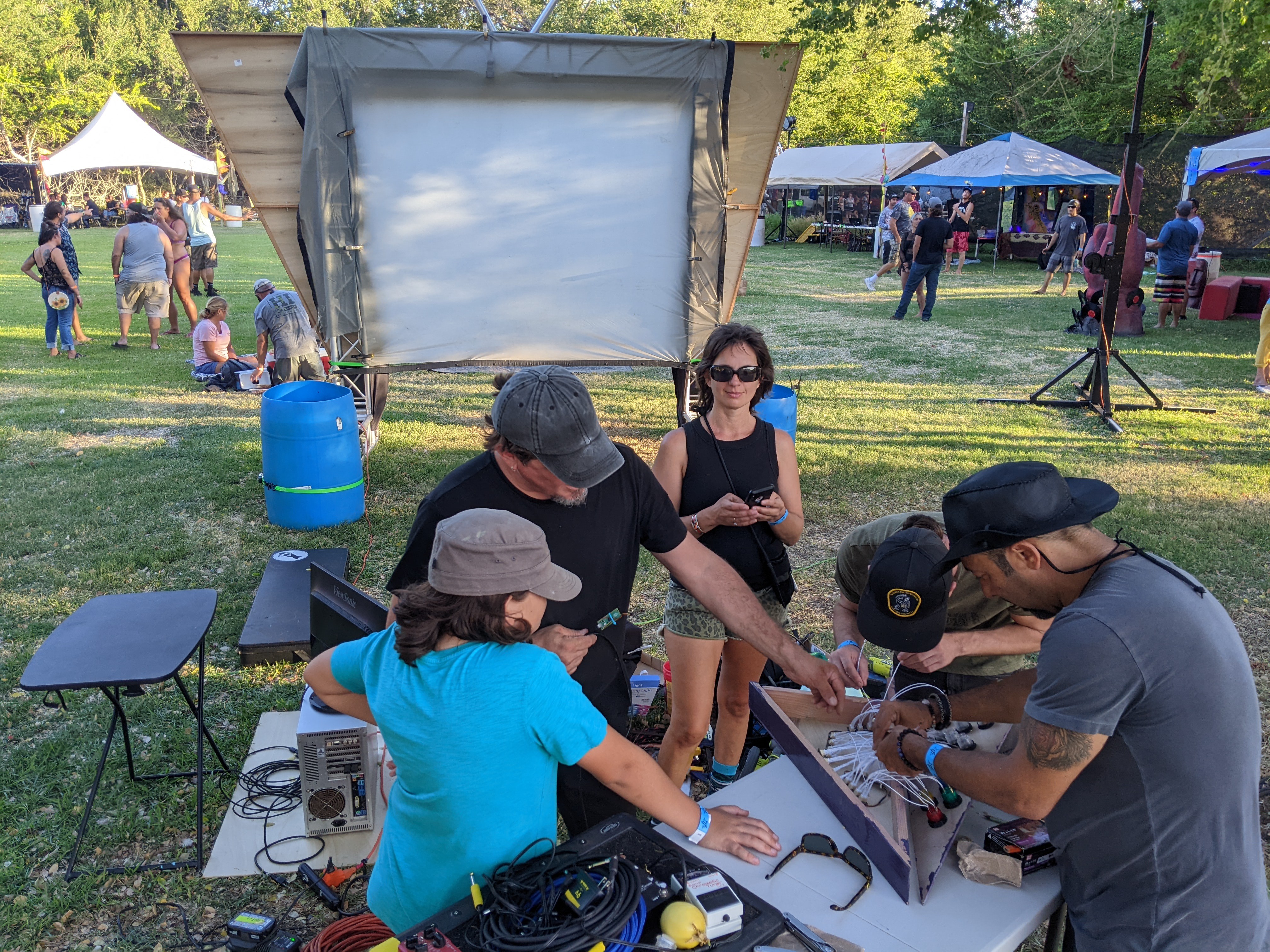
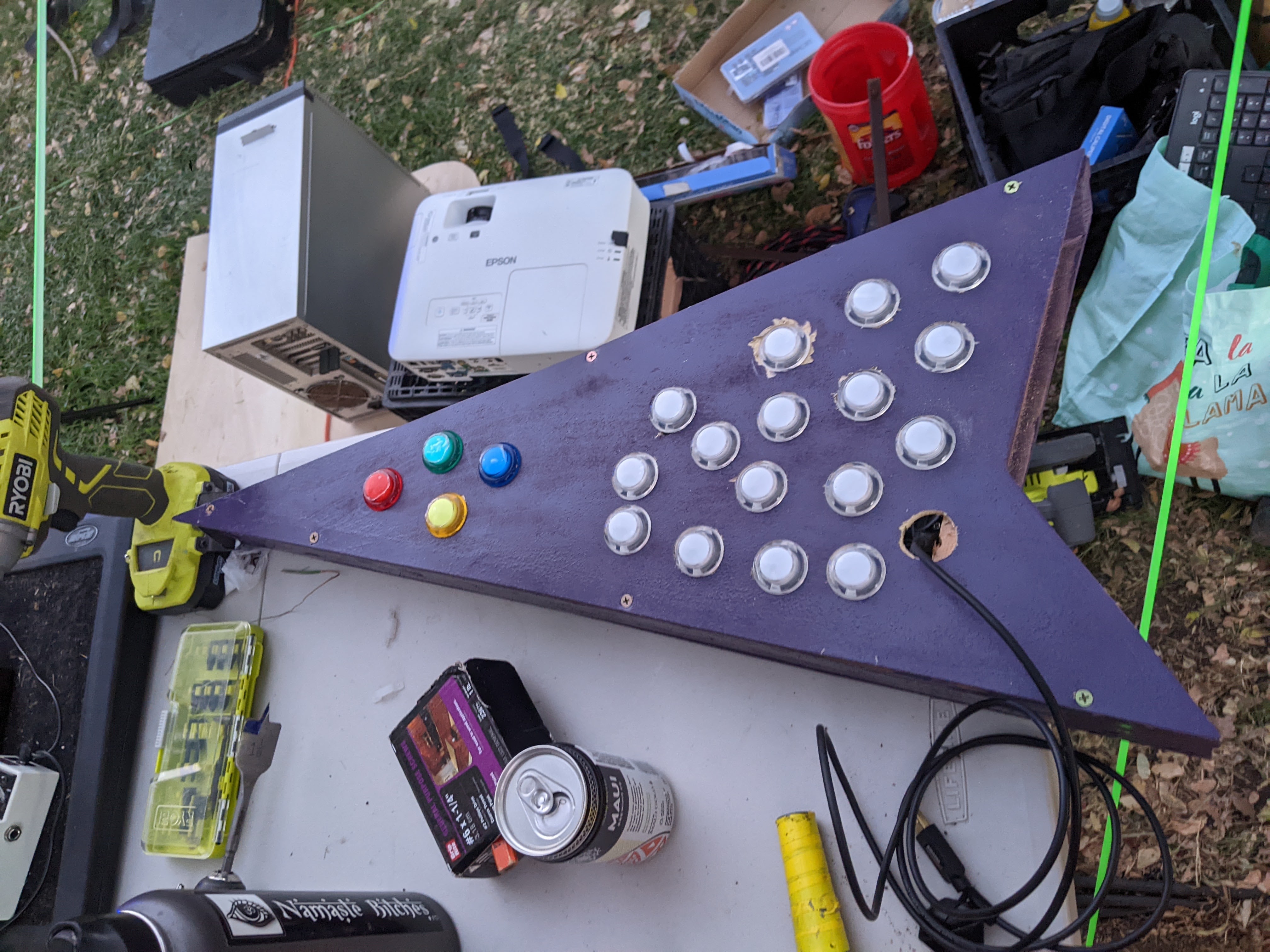
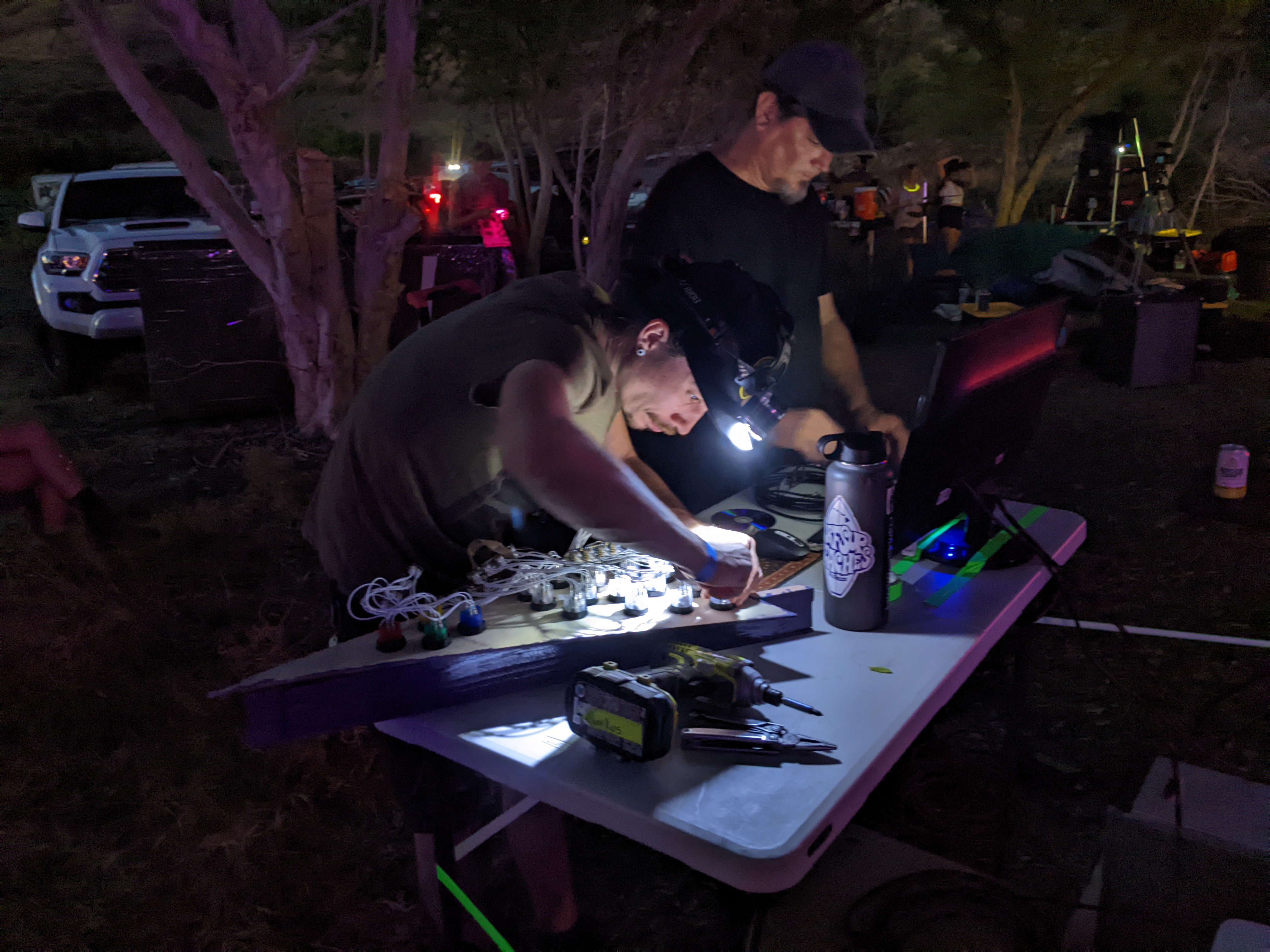
We are fabricating a custom case to hold the buttons. That is a whole other project that perhaps will be documented in the logs here.
Future updates *might* look at adding sliders or dials for midi Continuous Control (CC) or Pitch Bend, or switch out MIDI to HID interface to make a hot key pad. Probably also look into using larger buttons. In a previous project I hacked some neoPixel rings into 60mm buttons and it worked ok. I need to revisit that process.


 Justin Maynard
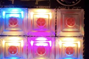
 DeckerEgo
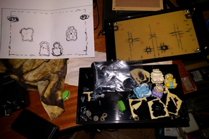
 David Karla
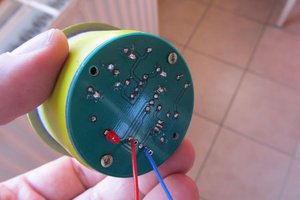
 Alain Mauer