JP Gleyzes
-
ESP32 HDD clock PCB
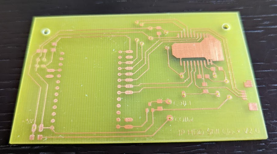
08/23/2022 at 09:03 • 0 commentsHere is the PCB designed to accomodate the ESP32.
![]()
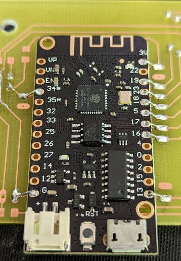
As you can see, the ESP32 can be soldered either using the through holes or "SMD like" as I did.
![]()
Eagles files (schematics and PCB) are available here
stay tuned for the code (will take a few weeks...)
-
ESP32 HDD clock schematics
07/31/2022 at 08:56 • 0 commentsAs promized, I am just starting to port my HDD clock on a new MCU : ESP32
This would have several adavantages:
- wifi and bluetooth are enabled. No need to connect to a PC via USB
- ESP32 lolin lite breadboard has everything needed: power supply, battery, USB to serial programmer
- no need for the RTC chip as wifi connection is available to get time over NTP
- easy to hook up an android App to this MCU
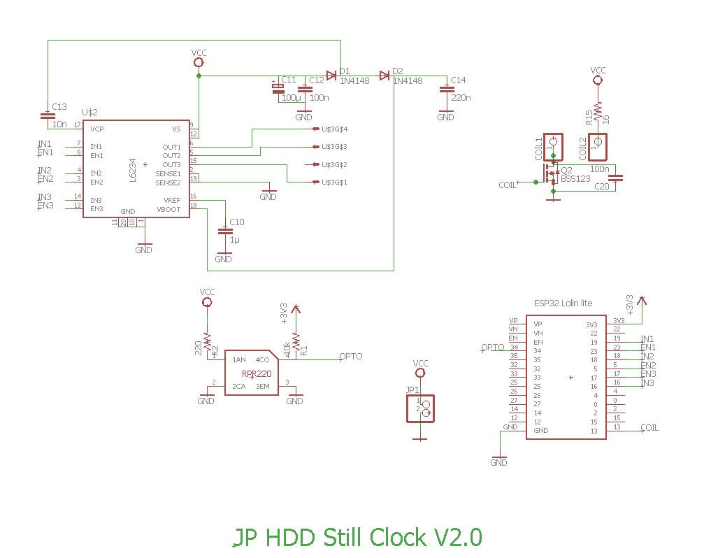
Here are the simplified schematics
![]()
It's indeed much simpler than the PIC circuitery !
- one mosfet is still needed to drive the coil
- one L6234 to drive the BLDC motor.
- one RPR220 as a position sensor.
-
Calibration of the heads arm coil
07/09/2022 at 08:43 • 0 commentsThe heads arm coil bhaves as a galvanometer.
However its behavior is not totally linear. Thus the minutes ticks could be a little unprecise...
A calibration procedure is needed!
I have choosen to calibrate the minutes every 5min. It meens that a multi linear curve is applied to fine tune the PWM value applied to the coil.
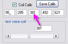
Once again you can use the PC application to interactively enter these calibration values. You will have to enter 5 values (00:00, 00/15, 00:30, 00:45, 01:00)
- check the box
![]()
- you can now move the horizontal scroll bar
![]()
- positon the arm to 00:00; 00:15 ; 00:30 ; 00:45 ; 01:00 and each time write the value in the adhoc text box (example for 00:30)
- save these values in eeprom
![]()
Your coil arm is now calibrated!
- check the box
-
Alignment of the photransistor sensor
07/09/2022 at 08:32 • 0 commentsYou need to align the phototransistor pulse on the 6th stable position of the motor and also align the clock platter to the 12h00 position.
The PC application is here to help you!
- tick the checkbox
![]()
- the disk will lock on the calibration position.
- unscrew the platter
- rotate the bottom disk until the led switches on
- rotate the top platter until it shows "12:00"
- screw again the platter fixations
As it is not totally easy to understand, have a look at this video
Your disk is now ready to run. Anytime the led flases, a full rotation is finished!
- tick the checkbox
-
Driving HDD BLDC motor
07/09/2022 at 08:06 • 0 commentsA Hard disk drive motor has more coils than this simple triphased motor. Practically I have found 24 stable positions.
![]()
The basis sequence of 6 positions is thus repeated 4 times. And 24 is a very convenient number for a clock !
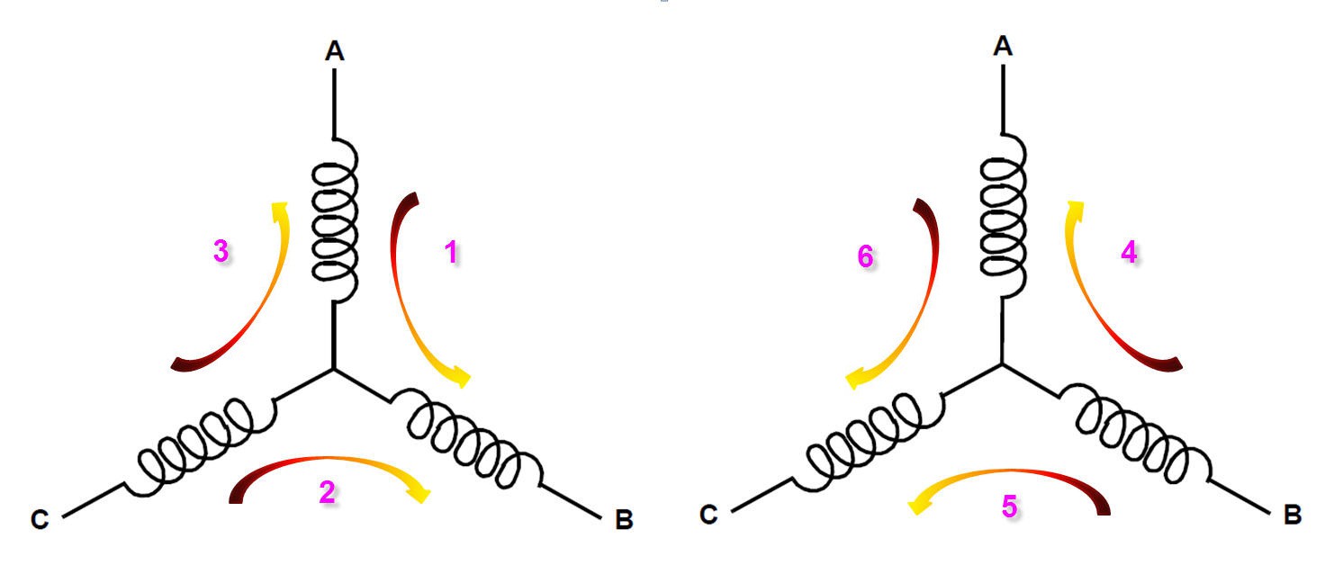
As we have 24 stable positions, we can have twice 12 hours marks very easily. Simply power the coils on the stable positions in sequence and the disk will jump as would do a stepper motor on these positions.
![]()
This being said we still need a way to trigger the coils depending on the current position of the rotor...
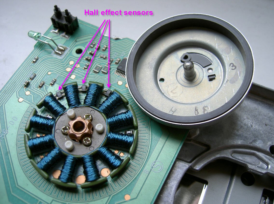
The simplest method to drive a BLDC is to have a motor equiped with hall sensors. These three sensors are positionned just in between the stator teeths and allow to trigger 3 successive stable positions of the rotor. (On the picture you can see an old floppy motor with its Hall sensors clearly visible). Note the positions of these sensors which are the same as the stable rotor positions on the above picture.
![]()
A hard drive motor does not have hall effect sensors... They use another technics to find the rotor position. This "sensorless BEFM" technics is efficient but much more complex to implement...
I have thus decided to replace the hall effect sensors by a single sensor : the RPR220 phototransistor.
This sensor allows me to check the 12:00 position of the clock and to check the stable position 6 of the rotor. The bottom platter must be carefully aligned with this stable position. I will show you latter how to do.
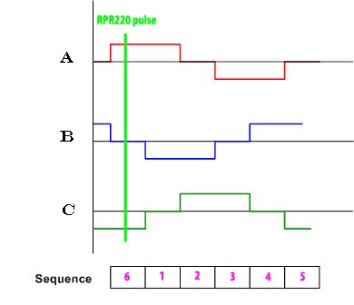
This being done, knowing that there are 24 stable positions, you just have to know the duration of a full rotation, to divide it by 24 to get the duration of a full step. You can commutate the position n°1 when you see the dark spot and then trigger the following 23 steps in sequence.
![]()
Basically it means that instead of having 3 hall sensors we only have one.... Thus if you want to rotate the disk you just have to "launch the rotation" using the stepper mode technics (increment the driving sequence one by one). when you see the phototransitor pulse you are on position 6.
Now go on pulsing the sequence but at higher speed and measure the time to see again the RPR pulse. Knowing this rotation period you can estimate the theoritical timing of the two missing sensors and trigger the respective pulses precisely. And increase the speed...
This is exactly what is implemented into the firmware. Simple and efficient unless you want to increase too much the speed... where the motor will stall!
It may seem simple but bear in mind that you have to start the disk in "stepper mode" accelerate it and when the speed is high enough switch to brushless mode. It can be a little tricky mainly if you remember that the disk is a 12V one powered only with 5V...
Of course the coils are not directly powered with 5V DC but are powered via a PWM signal to limit the current into them and to tune the rotation speed.
-
Electronics schematics
07/08/2022 at 13:29 • 0 commentsElectronics is based on Microchip PIC 24FJ256GB10. microcontroler. This 16 bits MCU has a native USB port which allows easy interface with a PC.
It has also 9 hardware PWM ports which are perfect to drive motors.
Together with the PIC we find :
- A triple H bridge driver L6234 used to pilot the motor
- a Reflective photosensor (photoreflector) RPR220
- a real time clock calendar DS1337C used to keep time when the power is off
- an audio amplifier MAX9716 for the clock to speak (to be done)
- a 3,3V voltage regulator
- a few SMD components to "make the glue"
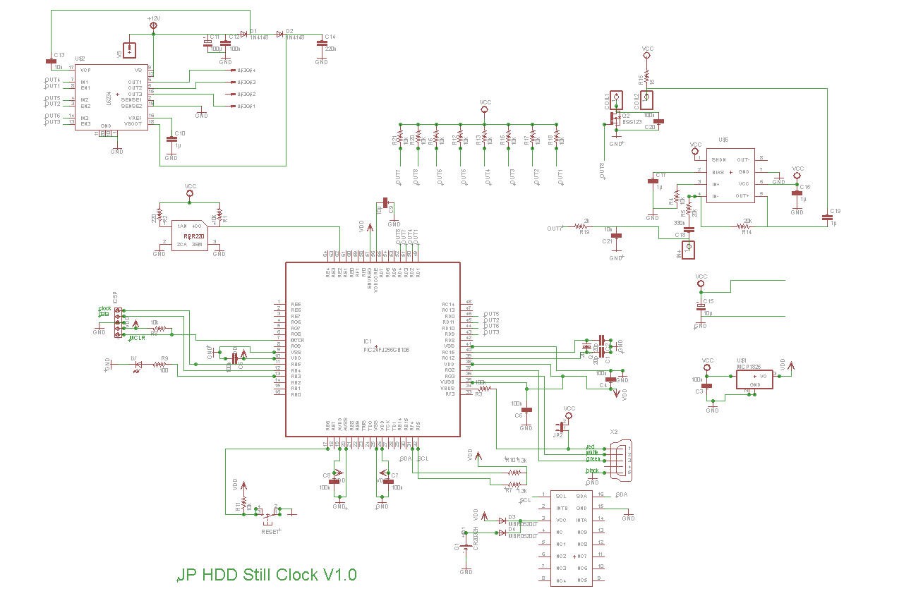
![]() The schematics are quite simple :
The schematics are quite simple :
![]()
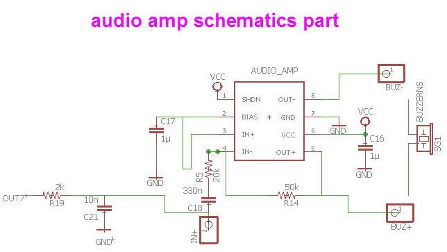
Note that you can safely forget the audio amplifier part which was only added there "for fun" (see the devoted log to be published)
![]()
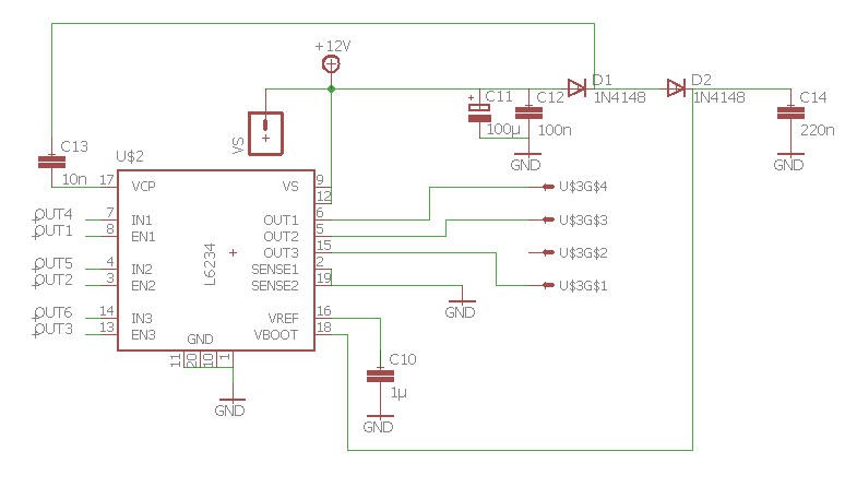
The motor is driven by the H bidge driver L6234
![]()
Its outputs are connected directly to the motor connector scavaged from the original board.
Note that VS pin is said to be 12V, but I do power this system only with the 5V DC coming from the USB plug.
It works, the motor is not rotating very fast but it is enough for a clock and the H bridge does not heat at all !
Furthermore, you do not need to add any external power supply, only a smartphone charger !
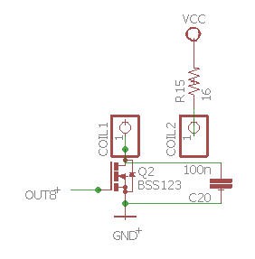
The heads coil is driven directly via a PWM pin issued from the PIC. The Mosfet is there to cope with the 3.3V limitation of the PIC's IO...
![]()
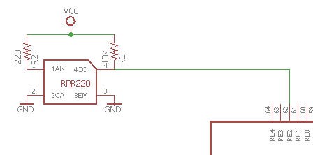
Finally the photo transistor is powered at 5V and is connected to a 5V tolerant input pin of the PIC :
![]()
That's all for the schematics which is finally quite simple.
You can find all the eagle files including PCB here.
-
Engraving the disk platter
07/08/2022 at 10:35 • 0 commentsYou need now to design a nice "clock platter".
The disk geometry is directly influencing this design.
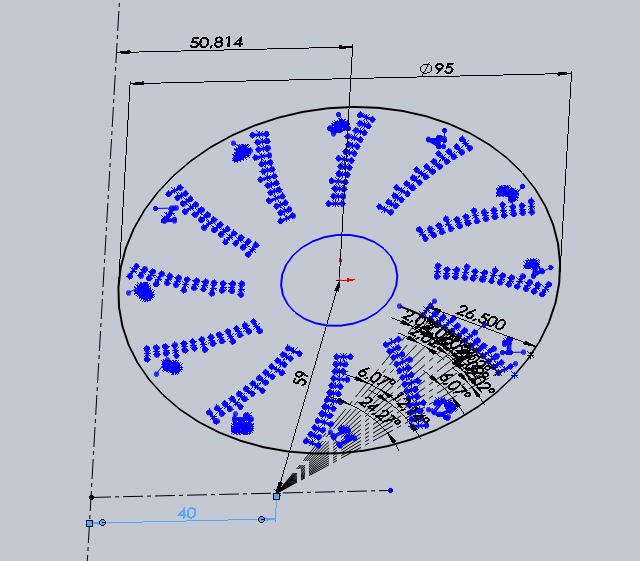
You need to make a precise plan of the disk, axis positions, head arm lenght... and to report all this into a CAD software. here is my design for my old samsung disk.![]()
Here is the dxf file for this drawing
A have tested several ways to transfer this drawing on the disk.:- toner transfer method with a laminator and a laser printer ( toner transfer). Result is clean but very fragile and there is a lack of accuracy when positionning the drawing on the platter. (see picture on top of the project page).
- V shape engraving with my CNC mill. Result is almost perfect even though signs are a little too wide...Here is the GCode engraving file
this video has been accelerated (High speed milling)
![]()
-
Adding a phototransistor to the disk
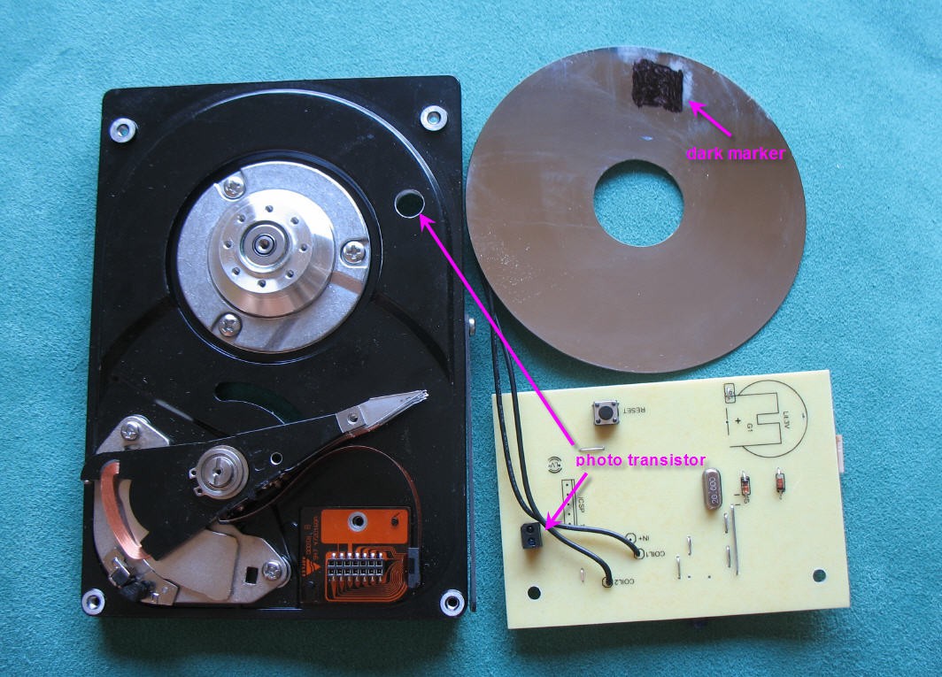
07/08/2022 at 08:58 • 0 commentsRPR220 phototransistor is soldered on the PCB and its led focusses IR beam on the bottom platter of the disk. A hole is drilled in the disk enclosure for that. A dark spot is painted on the disk to be detected easily by the sensor.
It is highly recommended to position the PCB on the disk before soldering the RPR220 sensor. Doing so will allow you to use the 4 pins holes to mark the disk enclosure and so to easily position the hole on the enclosure.
![]()
Idealy the phototransistor should fly at 6mm of the dark mark. Fine tune the pins lenghts if necessary before soldering.
However it is not that critical, a calibration procedure exists and will be described later. Provided that the phototransistor sees the dark mark, everything will be fine!
Similarly the dark mark do not has to be recise at all. Paint it manually on the disk using a permament marker.
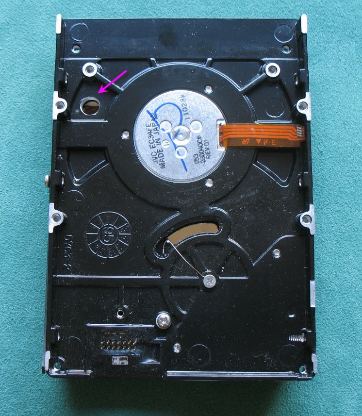
You can remove the original PCB, but take care to unsolder the HHD motor ribbon connector. It will be reuse on our new PCB.
Do not damage the motor ribbon!
![]()
-
Modifying the heads arm
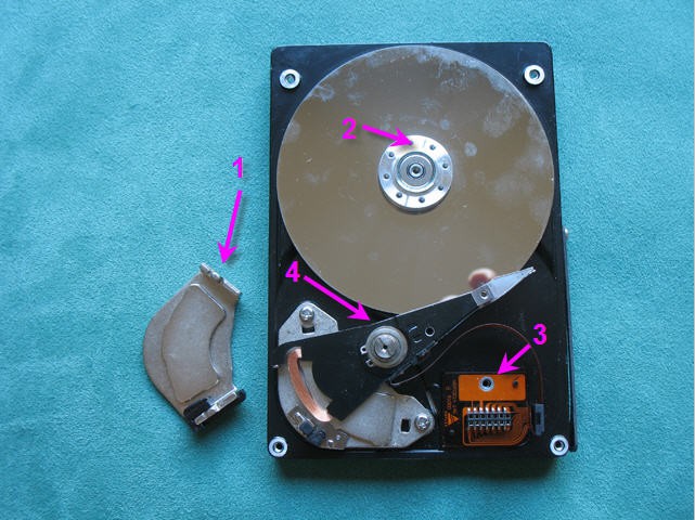
07/08/2022 at 08:17 • 0 commentsOpen your HDD and remove the heads arm :
- remove the upper half magnet
- unscrew the the platter locker screws
- unscrew the connector screw
- unscrew the screw on the central axis of the heads arm
![]() The magnet is very strong, it is uneasy to remove it. You can use a screwdriver to help you, but beware that the coil is very fragile... and is absolutely needed for this clock. Same thing for the connector and the ribbon!
The magnet is very strong, it is uneasy to remove it. You can use a screwdriver to help you, but beware that the coil is very fragile... and is absolutely needed for this clock. Same thing for the connector and the ribbon!![]()
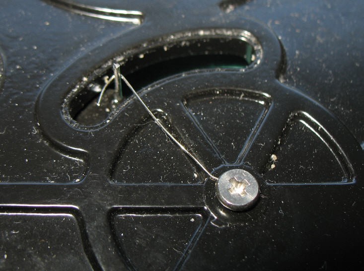
The heads arm must be equiped with a litlle torsion spring to convert it into a moving-coil galvanometer..
The torsion spring is dissimulated under the heads arm. It is totally not visible.
![]()
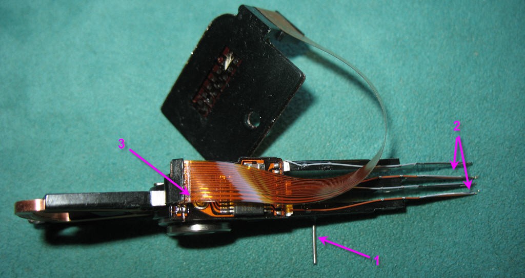
- the heads arm is drilled and a piece of piano wire is epoxy glued in the hole
- the heads are properly removed and their fixations are slightly bended to avoid to touch the disk. .
- You need to find the two biggest wires on the connector. They shoud be the coil connections. We will use these connections to power the coil.
![]()
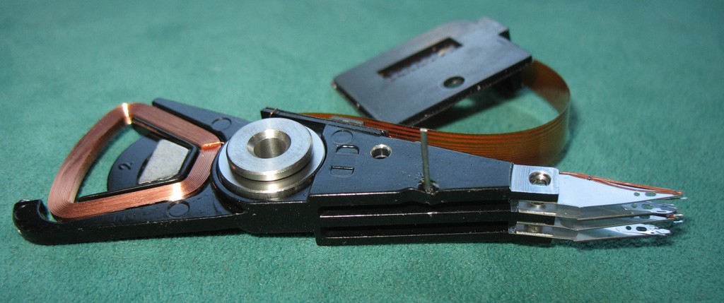
Removing the heads can be a delicate operation. Take your time, do it cleanly at least for the upper head (the only which is visible and used a the "hour pointer". So my advice would be to finish by this one and learn on the bottom others !
![]()
-
choosing the right HDD
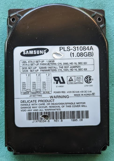
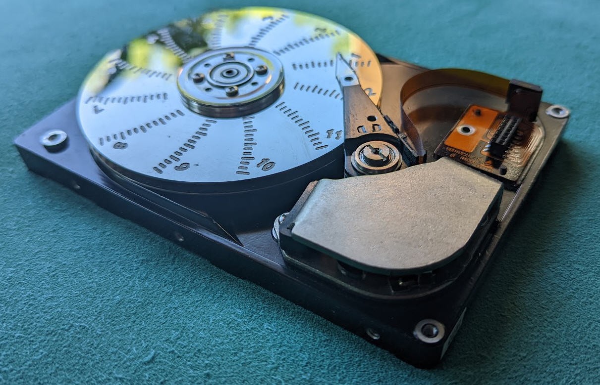
07/08/2022 at 07:52 • 0 commentsI had in my electronics garbage this old Samsung HDD
![]()
You can still find similar products on ebay. (Google search for Samsung 1.08GB HDD)
SAMSUNG WN310820A (1.08GB) with Firmware FH100 Information
Common characteristics Manufacturer Samsung Model SAMSUNG WN310820A (1.08GB) Capacity 1 GB Interface PATA Performances Maximum interface speed 16,7 MB/s Maximum read speed 2 MB/s Minimum average access time 18.0 msec Their perfomances are not exactly impressive, but smart enough to build a clock !
And they do have a lot of advantages:
- internal bowels are "on top" the enclosure after removing the cover. They are totally visible which is nice!
- they do have 2 disks platters which is mandatory
- the heads arm is sharp and thus will make a perfect pointer
- black color is very tendance and enhances the shining platters!
![]()
Hard Disk Drive analog and digital clock
How to build a fully working noiseless HDD clock. Almost a piece of art !