-
Designing the next version.
08/04/2022 at 04:48 • 0 commentsRunning simulations on the vacuum module was helpful in an indirect way. The simulations in itself aren't able to predict how well the extractor was able to remove particles from the air stream. It isn't using the correct numerical model currently implementing the correct one is a little far at the moment. Any understanding I was able to get was mostly about the shape of the air. It is kind of like having an idea in your head but drawing that idea makes it easier to develop that idea. In this case the it makes it easier to see where air isn't either providing a function or at least illustrating inefficiency.
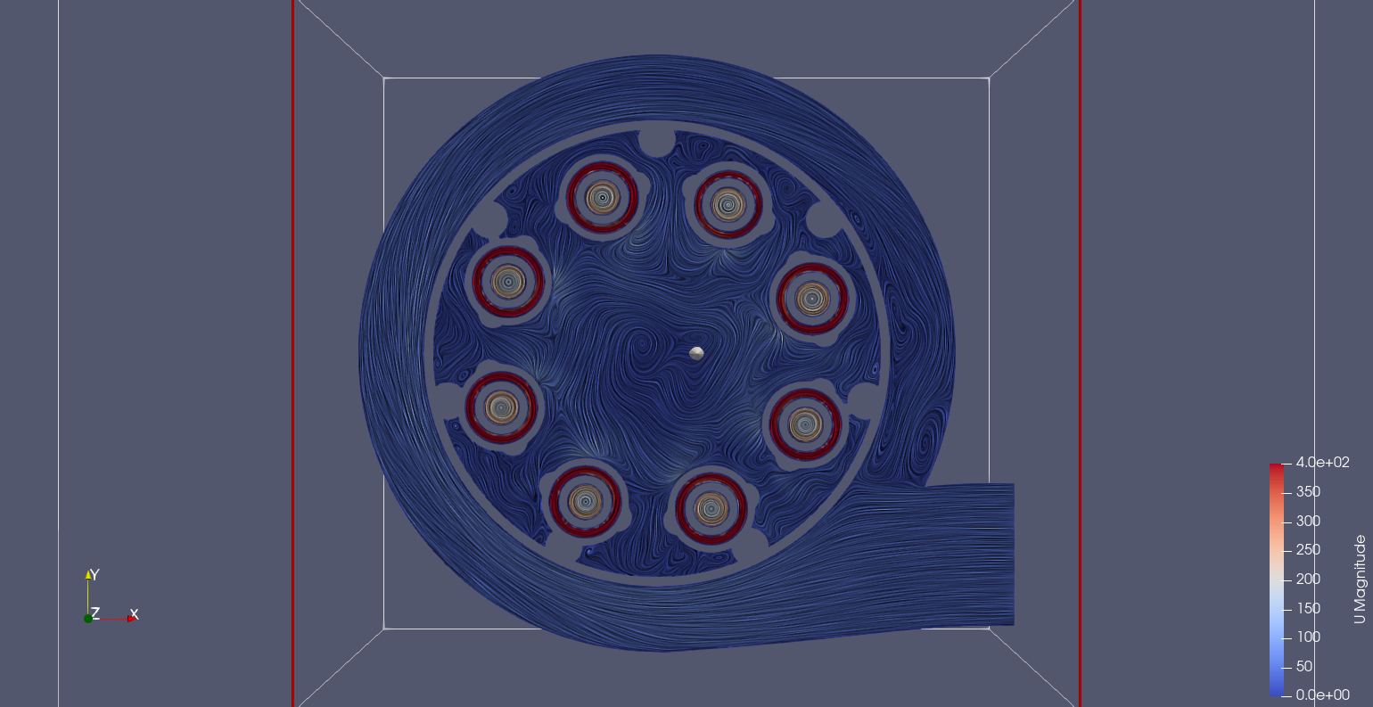
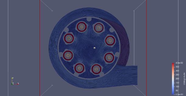
The following series of images picks out pockets of air that aren't coherent with the surrounding air movement and could be areas of improvement.
![]()
inlet from the outside air ![]()
highlighted section is turbulent When the air ducked in from outside it will rotate around the outer chamber. Th e problem is that when the air wraps around the chamber it collides with the air entering the chamber. Though the air is just pushed down it is done b a pocket of turbulent air. This may be just inefficient but because the velocity is used to separate the dust it is likely also ineffective for its removal.
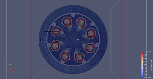
Similarly with the inner cyclones there is a section where the air slows according to the velocity colour map and the arrow.
![]()
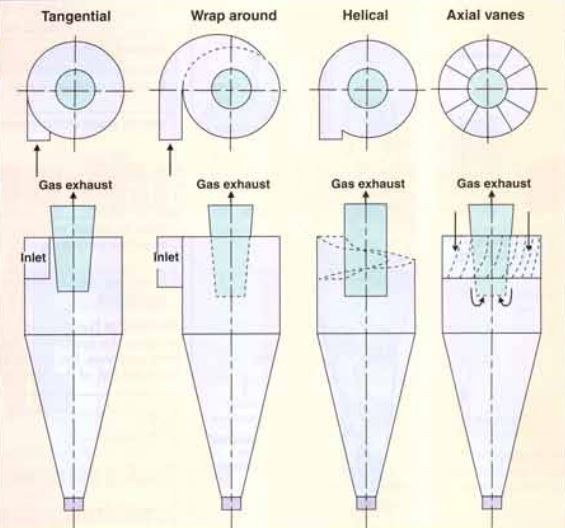
Preventing this would mean the air enters the cyclone chambers either directed downwards or by a longer entrance, eg wrap around or helical.
The helical approach looks appealing, especially considering dimensional constraints.
-
Trying to justify a design
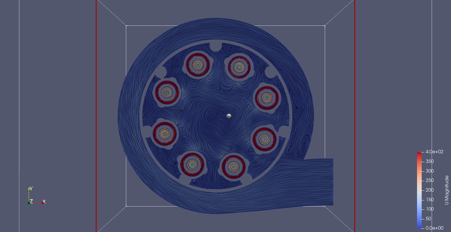
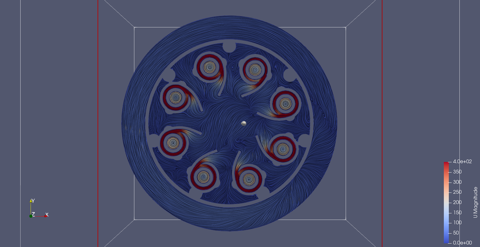
07/24/2022 at 13:56 • 0 commentsThis is the beginning of the design improvements and justification using fluid simulation, CFD. Using OpenFOAM these images are just an illustration that the simulations are working.
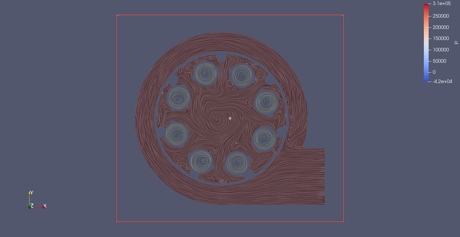
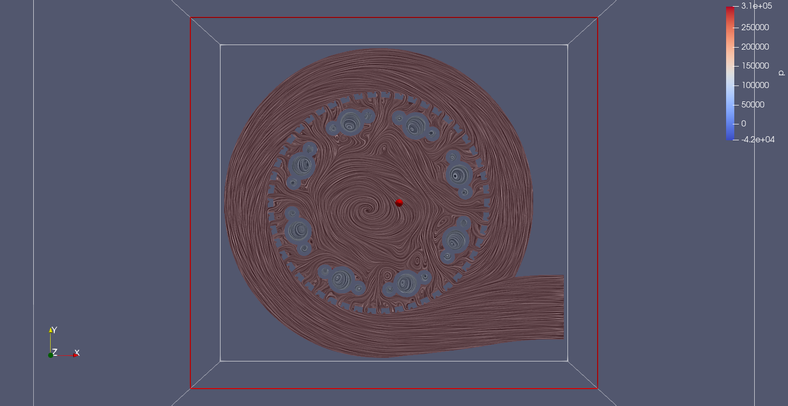
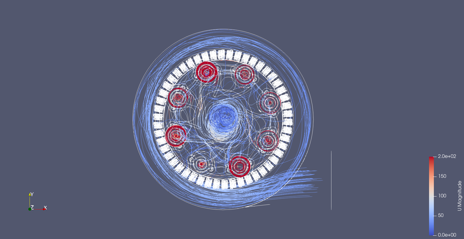
Z-axis slices with Line Integral Convolution, LIC to show air movement.
![]()
![]()
These results aren't fully converged as the pressure that the inlet was initially needed to generate a result. A pressure gradient a full vacuum, -20kPa, was difficult to set as the boundary condition. Surprise vacuums are difficult to simulate...
![]()
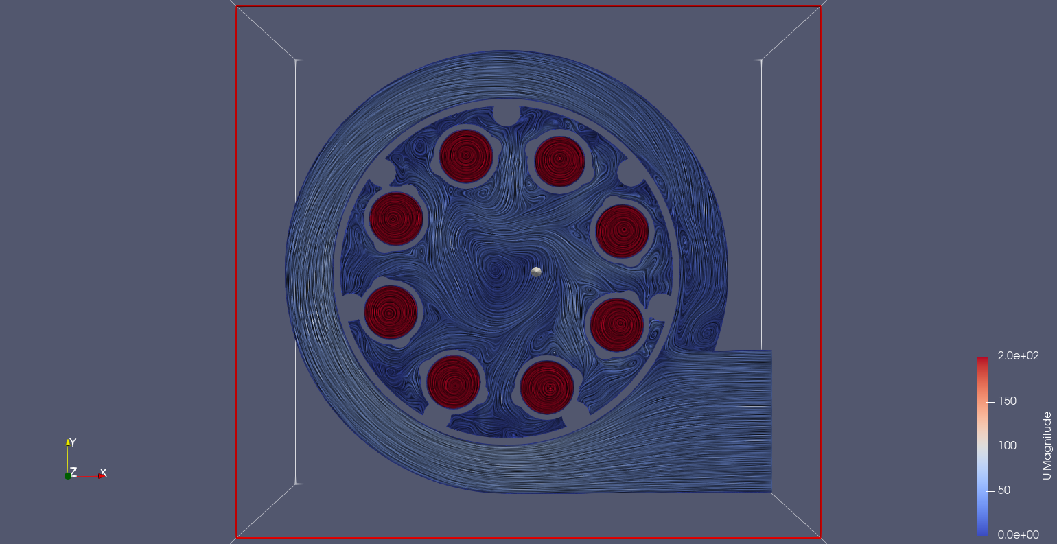
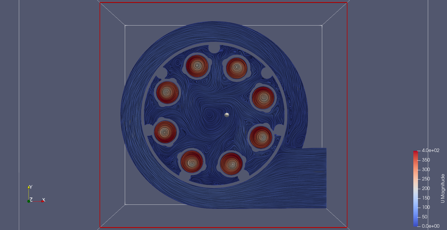
A different scale is applied from here on.
The bright red from the small cyclone generators sits just below the inner division. There is high velocity circulation inside these chambers. Doubling the scale show the lower speed of the cyclone core. Interestingly the chamber that supplys the small cyclone extractors has an amount of rotation despite passing through the outer mesh.
![]()
A slice taken when the small cyclone is divided between inner and outer represents the division that the extractor relies upon to separate the solid material.
![]()
Just at the entrance to the small cyclone you can see where the air is being pulled. Obviously it comes off the mesh, but the fact it looks to come from bellow may suggest alternative geometry is possible.
![]()
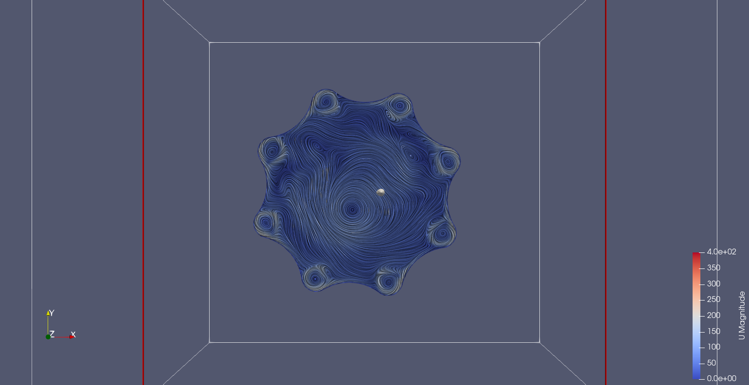
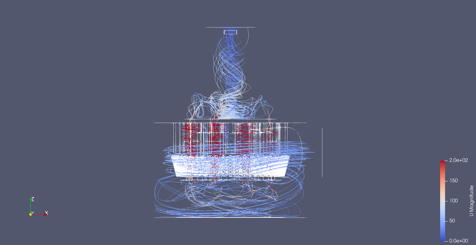
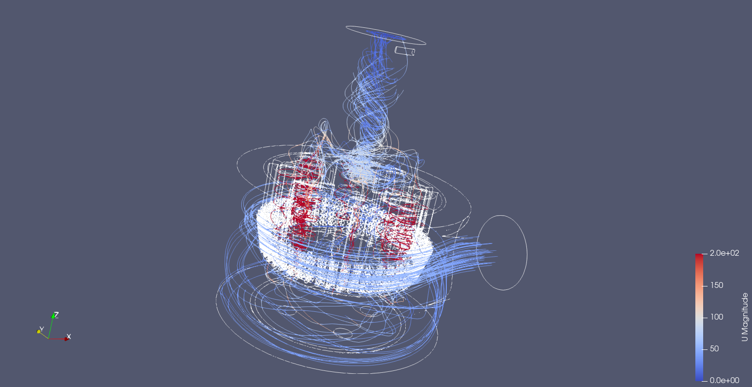
The exit funnel has a rotating column fed by the eight small cyclones, the streamlines illustrate this nicely.
![]()
Streamlines. Note the rotating column in the outlet funnel is attached to the roof of the extractor shell. This rotating column is also fed by the small cyclones low down in the funnel.
![]()
![]()
Interesting shot of how the velocity of the rotating air is slow in the middle. It would be interesting if this rotating flow structure continues far into the hose or it breaks down causing an inefficiency/blockage.
![]()
-
Background
07/24/2022 at 07:27 • 0 commentsThis project has gone through a number of concepts that have reached a seemingly working solution for a "shop vac". That is the extractor design is more similar to how woodworkers add a cyclone extractor to an existing vacuum system to remove the larger particles or wood chips. These large particles are collected in a bucket with the extractor bolted to the lid. An array of small cyclones are situated inside the outer chamber to collect smaller material. Its not clear how well the extractor removes small particles.
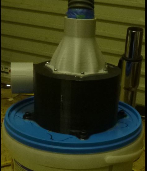
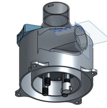
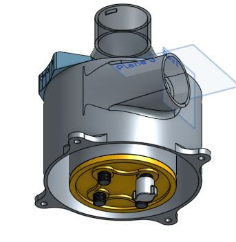
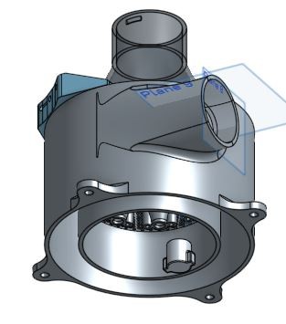
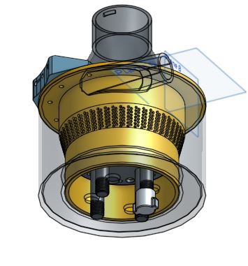
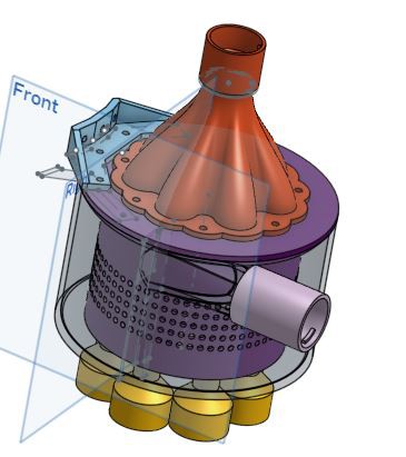
1. last version (v3.1) mounted on a bucket. All of the modelling was done in Onshape and can be accessed in a public document, but I'll go through why the model was made the way it was and the subsequent version after.
The primary driver of the extractors dimensions is the fact it is designed for printing. A benefit of bolting it to a bucket lid is that it can be printed in one piece, at least the main body. The outlet funnel is printed separately.
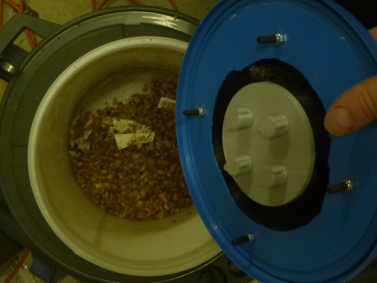
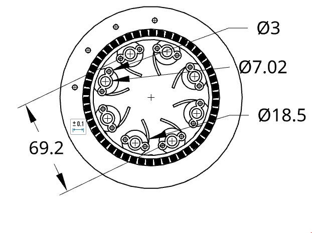
Those threaded legs are part of a piece sectioning off an inner chamber that is supposed to collect the small particles extracted by the second layer of cyclones.
It does fine job removing coffee chafe... and some paper. The guides for the suggest the direct of the air which is the same as the inlets direction. This is assuming there is any direction after the air passes through the mesh of holes separating the outer cyclone to the inner.
Here is probably the biggest learning from these model iterations. It is that bigger material needs to be filtered before it enters smaller cyclones because things like hair and small bit of paper clog them up. Once extractor doesn't have a cyclone, they do not function at all. This is one reason that an additional filter, like a HEPA, needs to be run is series with this type of system. Not just a cyclone system cannot filter all the smallest particle, but also if the cyclone fails. As such, it also influences futures developments of this system and why a bolt on modular extractor makes sense, as it still needs an existing high functioning fine dust filter. Adding a module like this just helps reduce the number of filters that you would consume, that's the aim at least.
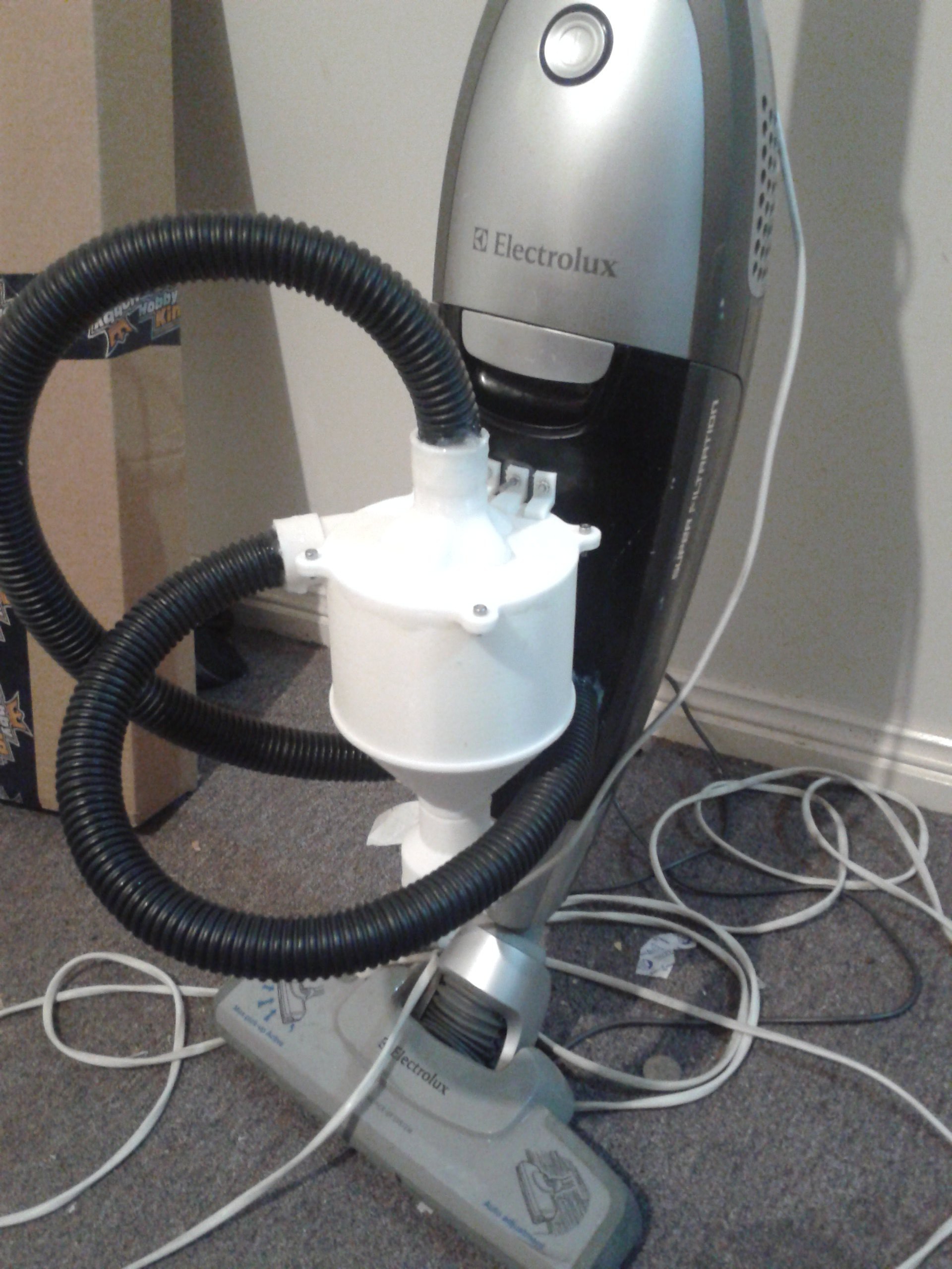
Add this extractor to and existing domestic vacuum cleaner is a bit more challenging.
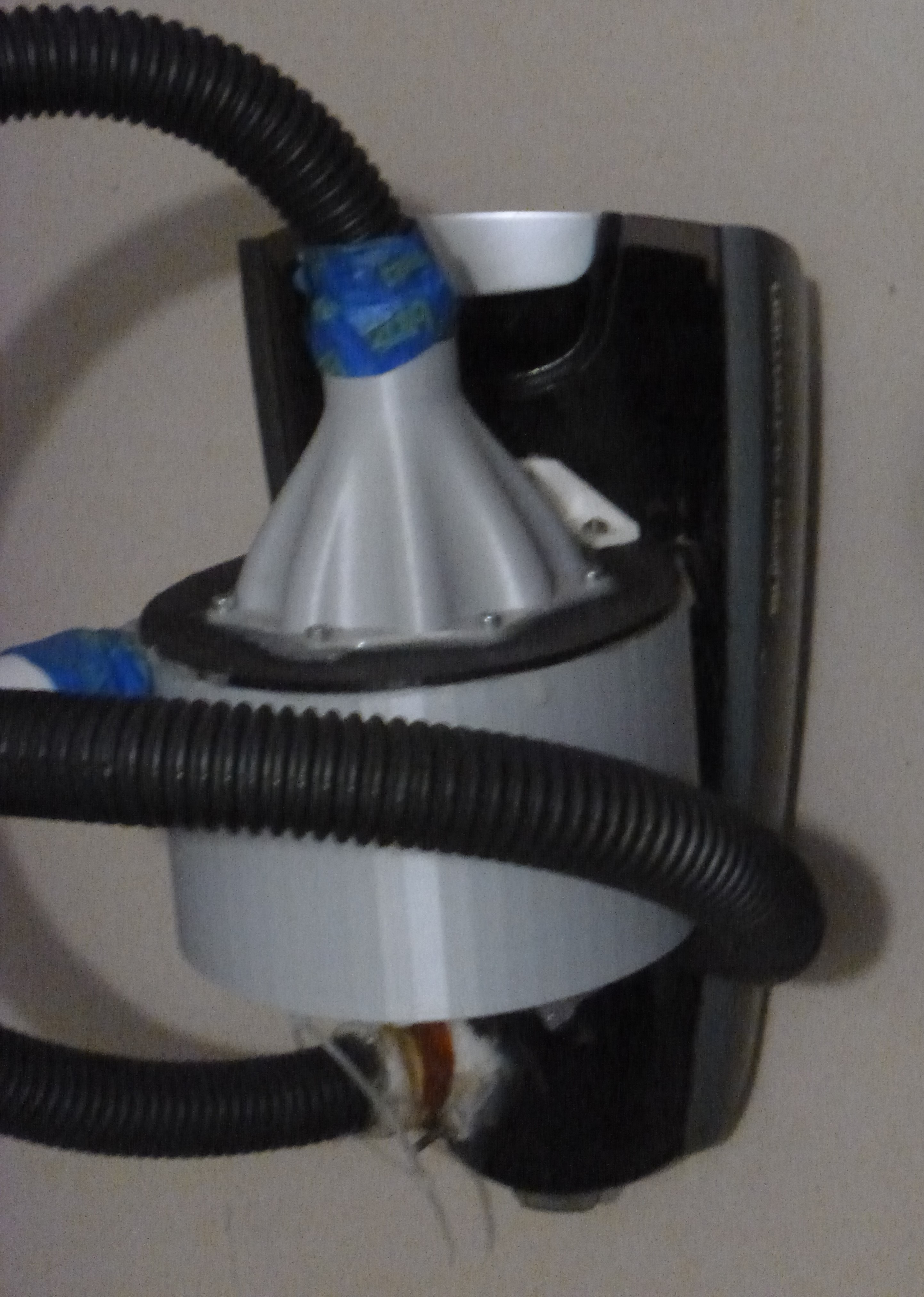
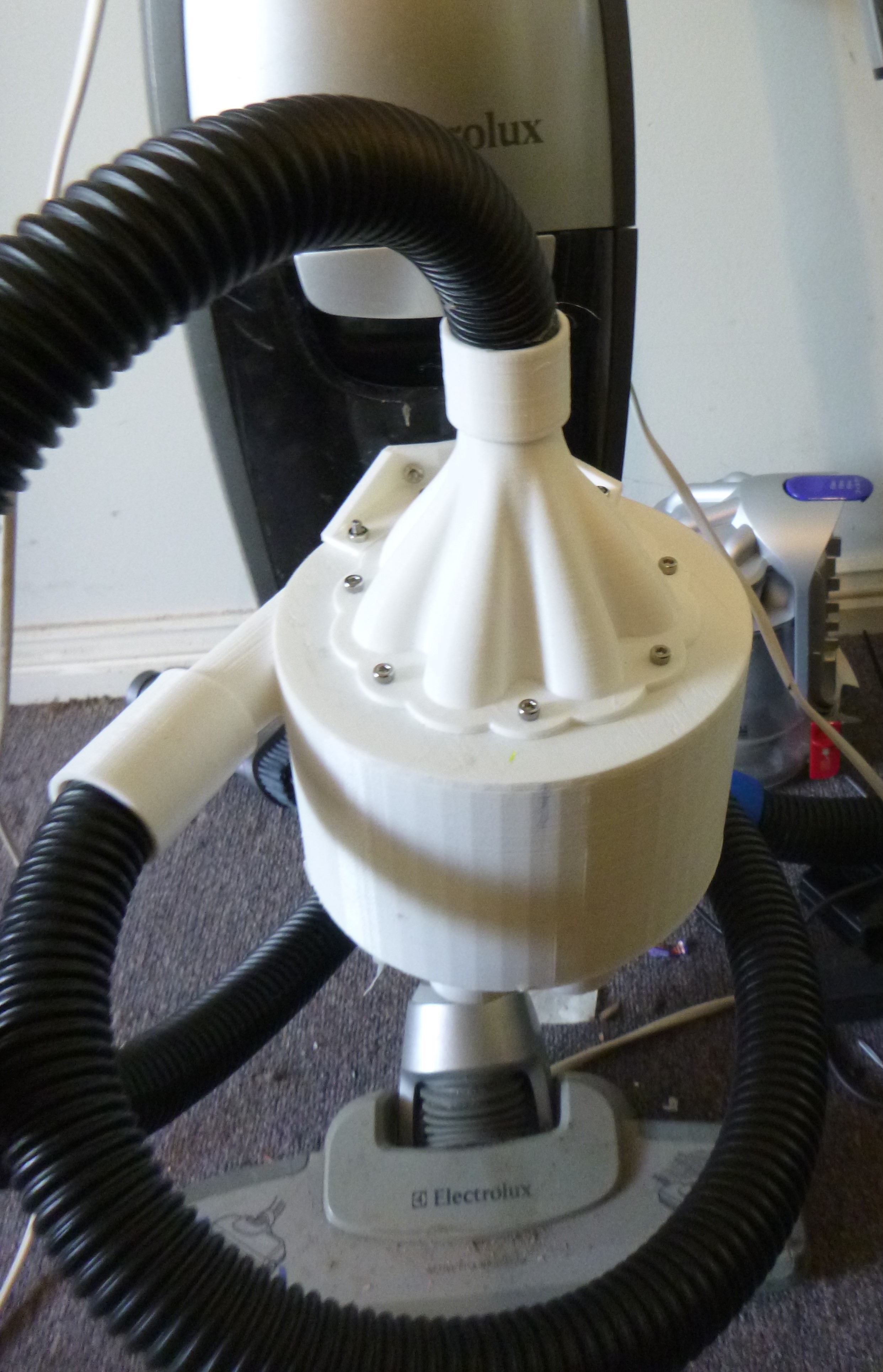
The same version as the one mounted to the bucket but to a vacuum. Ideally you would want this as small as possible. In the theory that these cyclonic vacuums use, the smaller the more efficient.
One of the biggest problems with these specific module is the sound from the hoses. They are irrigation hose and they aren't flexible, but they have a high pitched scream they let off when air is pulled through. Initially I thought is was the seals so I gummed them up with silicone. It wasn't until I made the one with the larger attachments mounted to the bucket did the screaming stop...
This module was based off a previous version and it mostly reflected easier to use design. The whole outer shell can be removed that has collected both chambers, the outer and smaller inner.
There are clear similarities between this and the previous version.
![V.2. extractor V.2. extractor]()
The issue, more than the problem, is the outer shell is attached by the small chambers collectors. This concept seemed to work with the outer chamber collecting an expected amount of detritus.
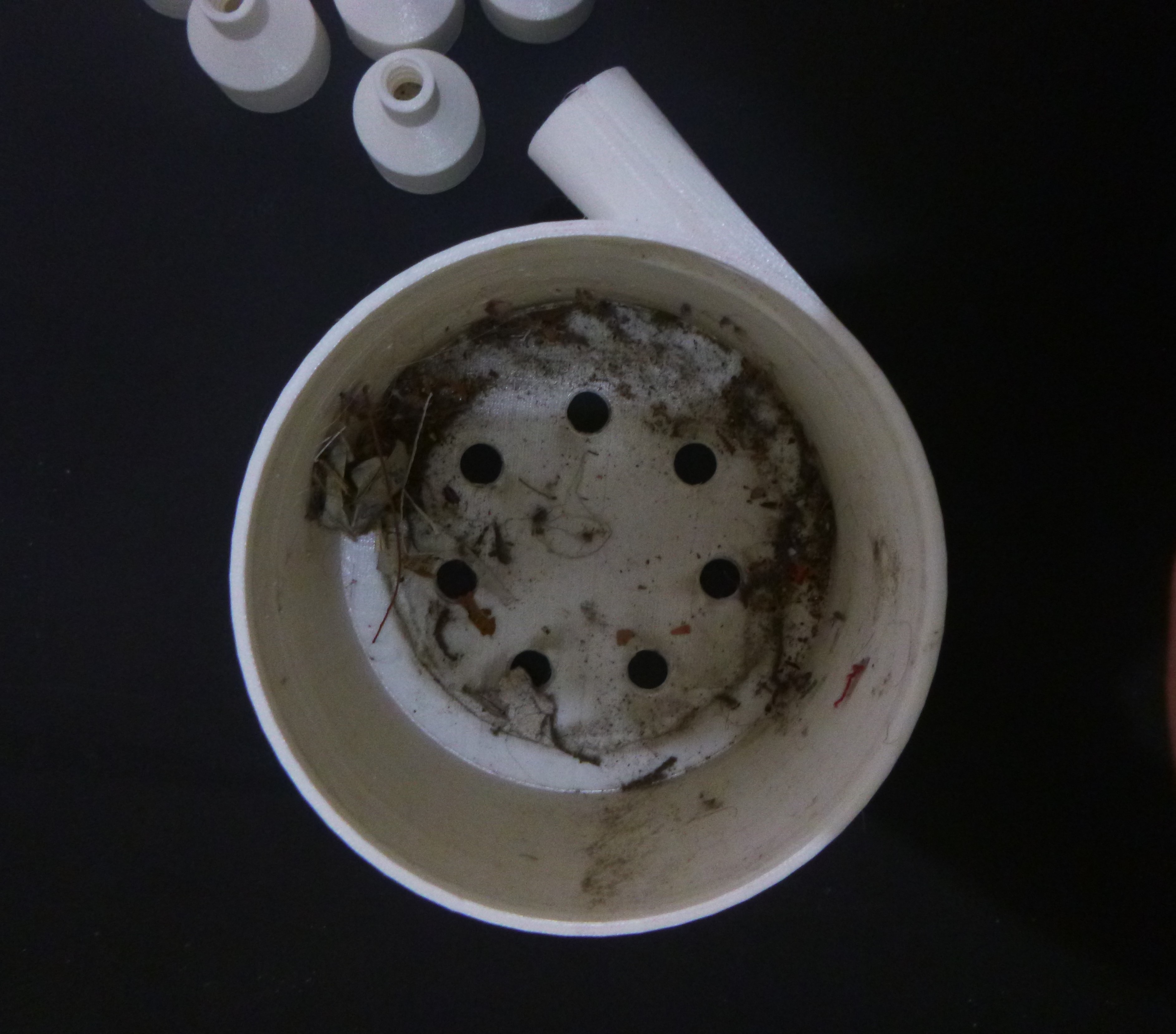
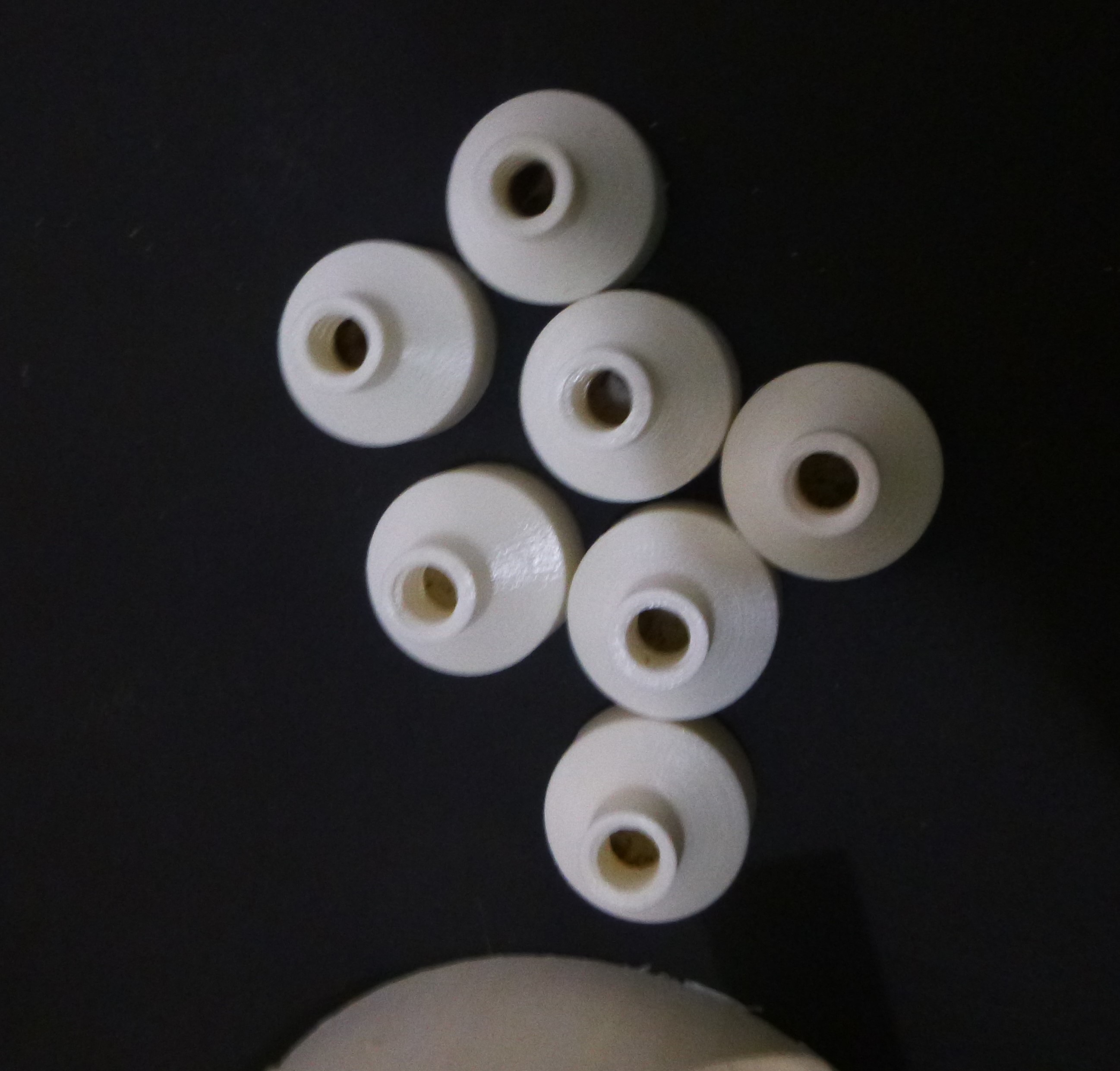
The smaller cyclone collecters also have an amount of debris in them.
![V.2. collectors V.2. collectors]()
Understanding where this dirt comes from is yet to be understood, but there is more that just some that fell in.
This was a step change from the previous and first concept where, I guess I was trying to be to clever. However, this was on top of all the required attachments and they got carried through the project, even the screaming hose.
![V.1 extractor mounted V.1 extractor mounted]()
This version didn't have a separate chamber collector. It initially worked, but the it didn't.
Adding a mesh to keep out the larger material that stopped the small cyclones from working as intended broke it completely. All the air ended up being pulled through the small cyclone outlets.....
Dust Extractor Module
This project documents the design of a modular cyclone dust extractor to complement an existing vacuum cleaning system.
 Nelson Phillips