Jamie
Jamie-
The final update
04/14/2024 at 10:12 • 0 commentsI apologise. I neglected these logs during development. It's not you, it's me.
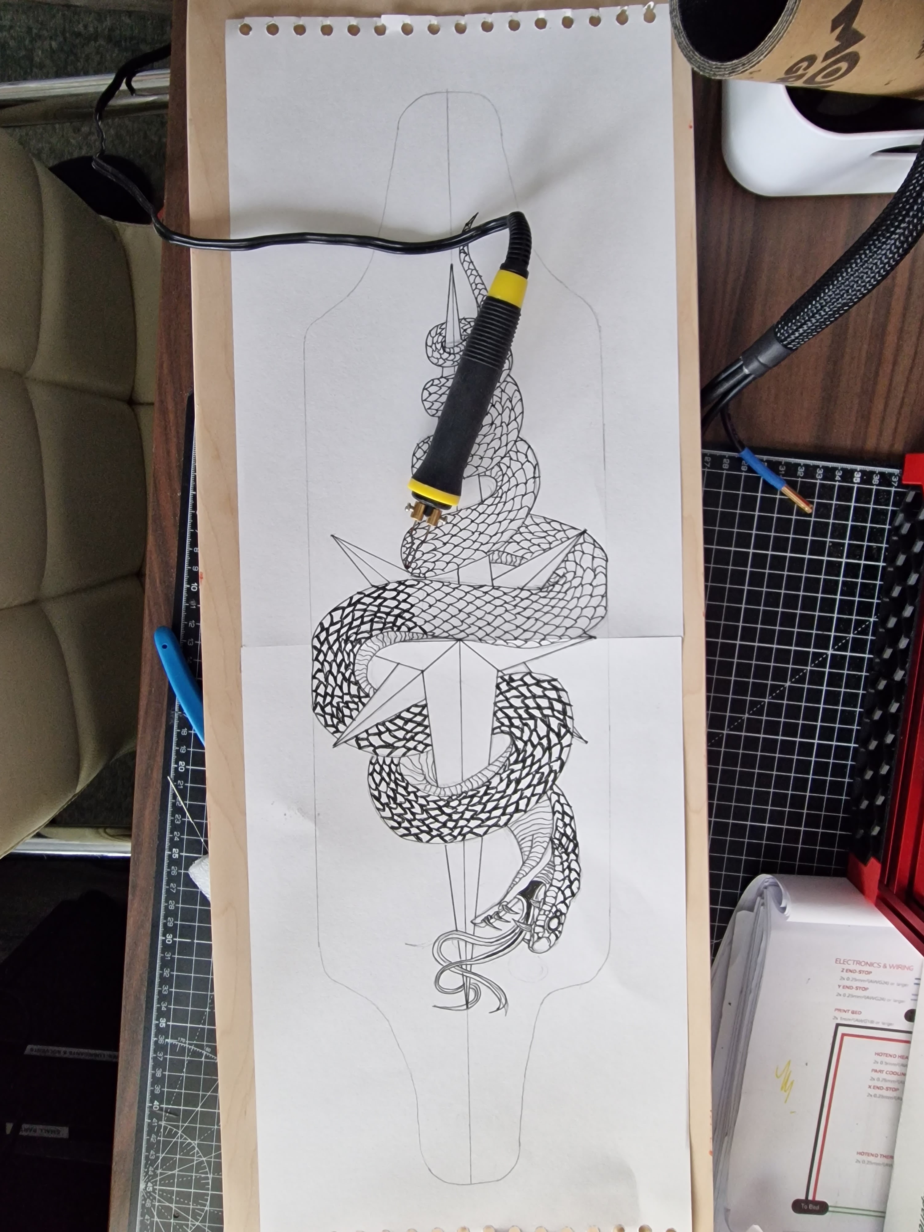
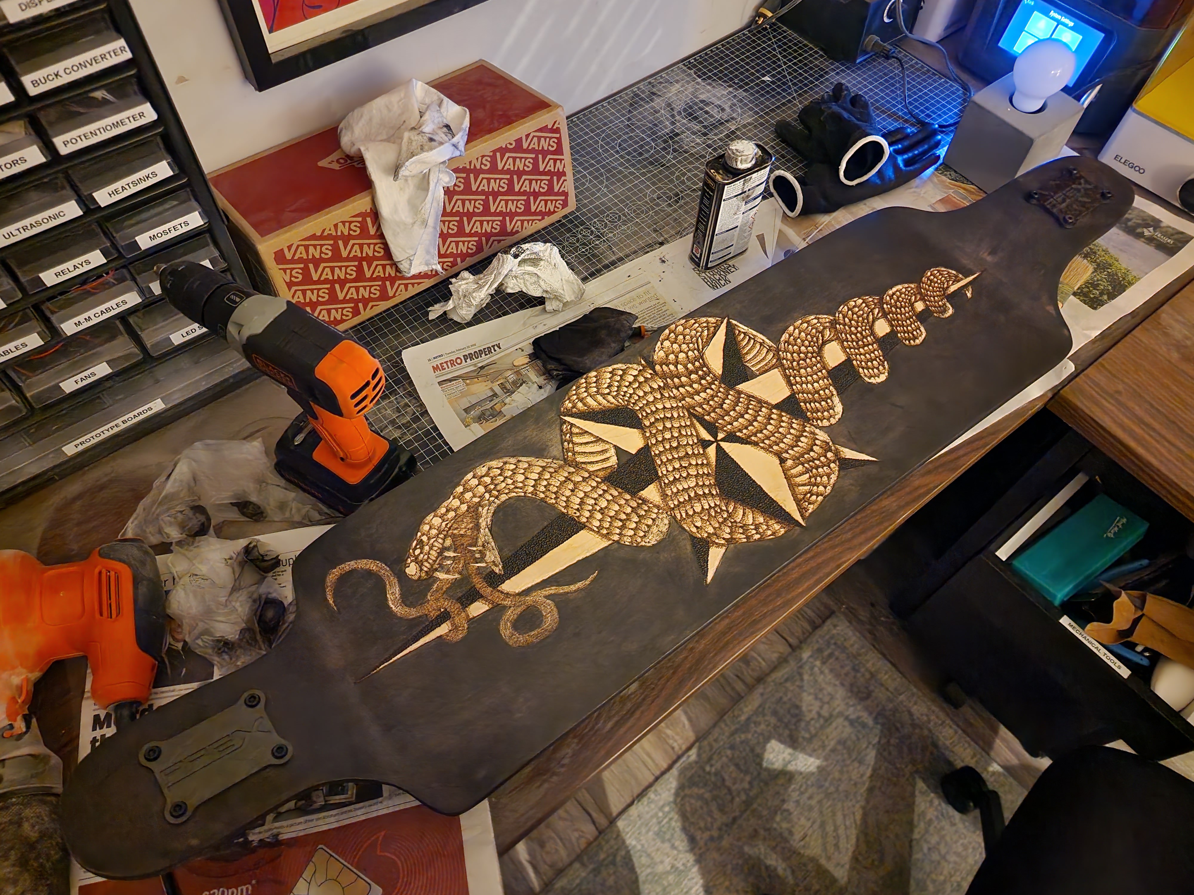
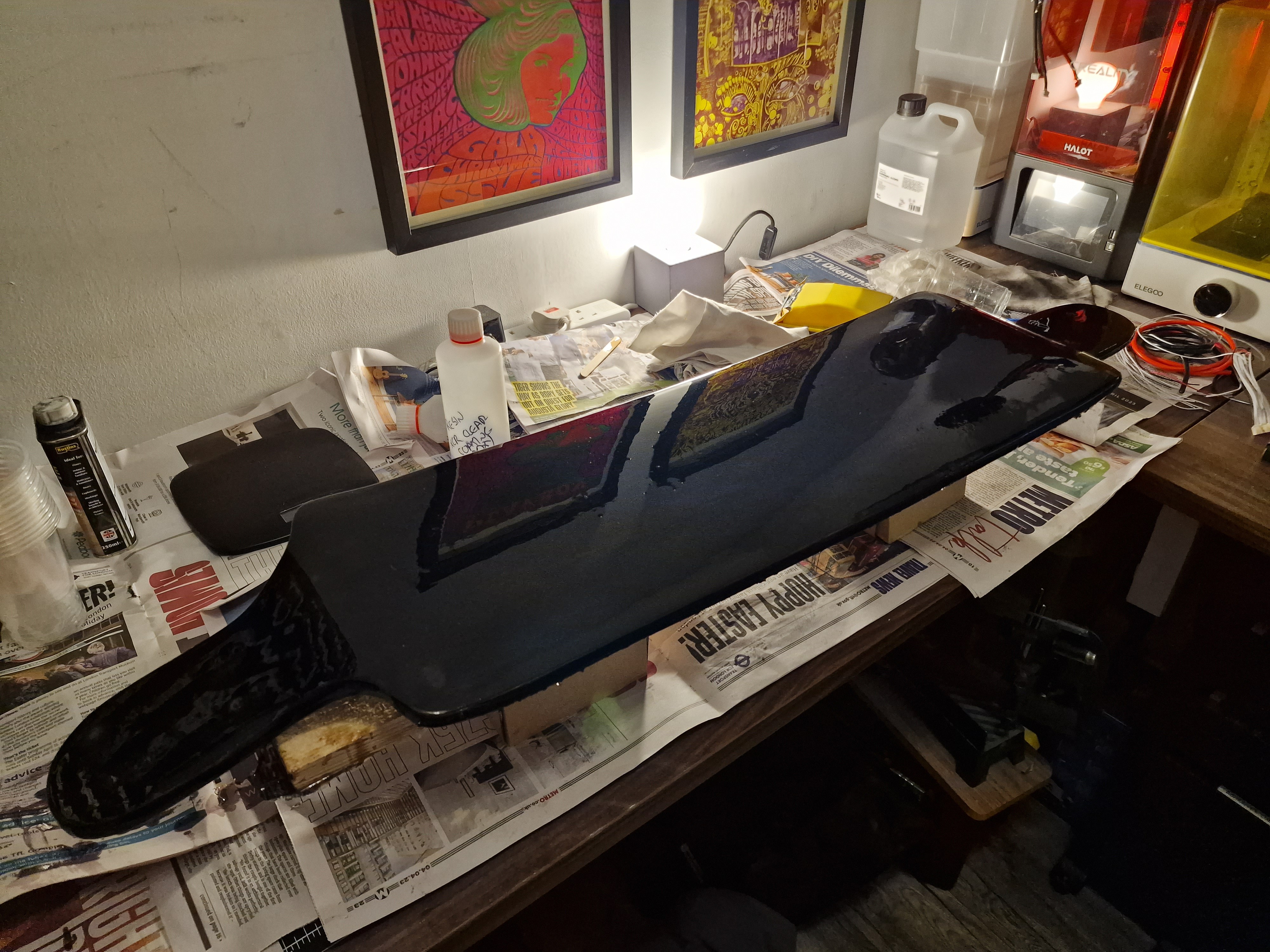
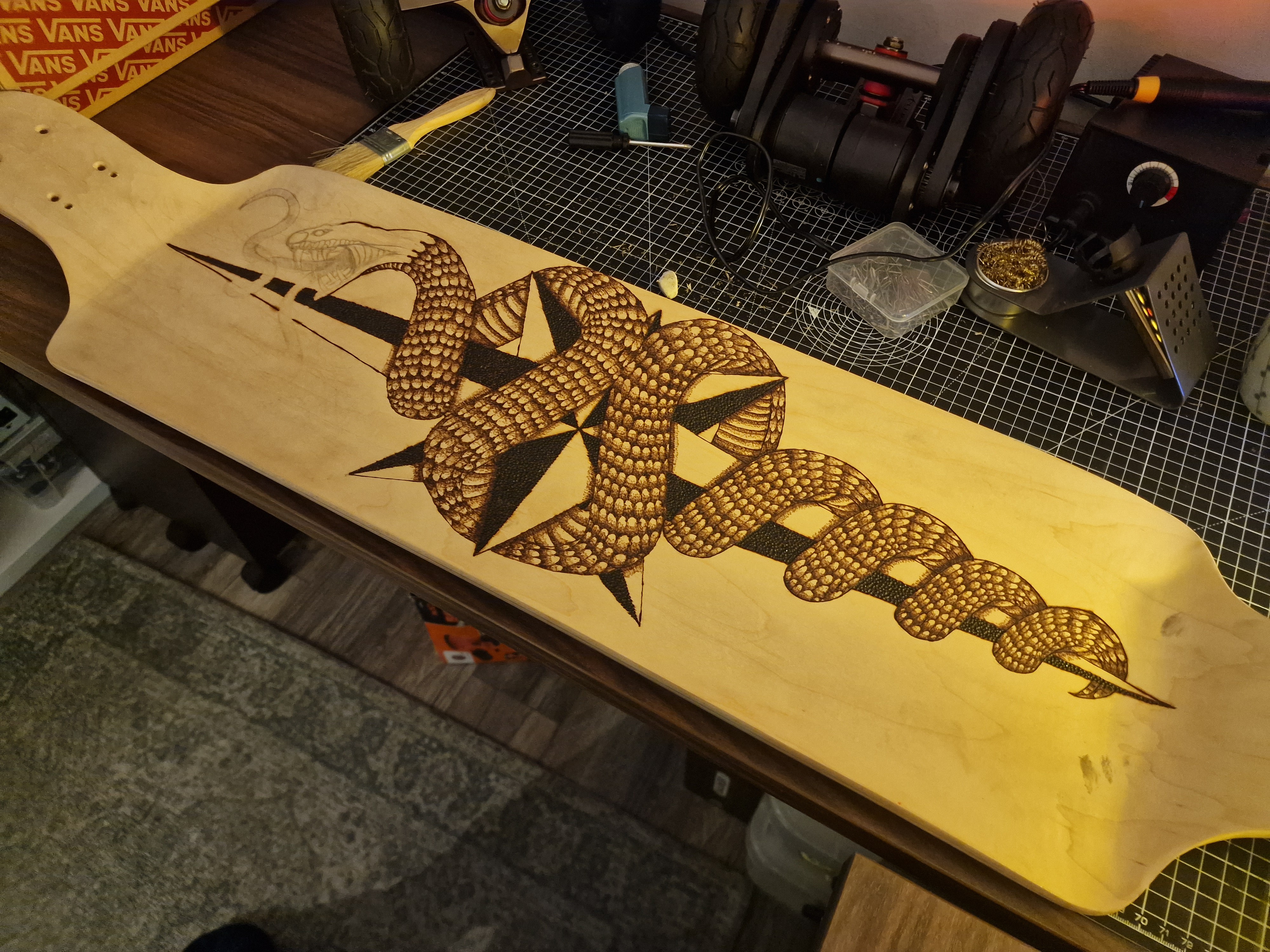
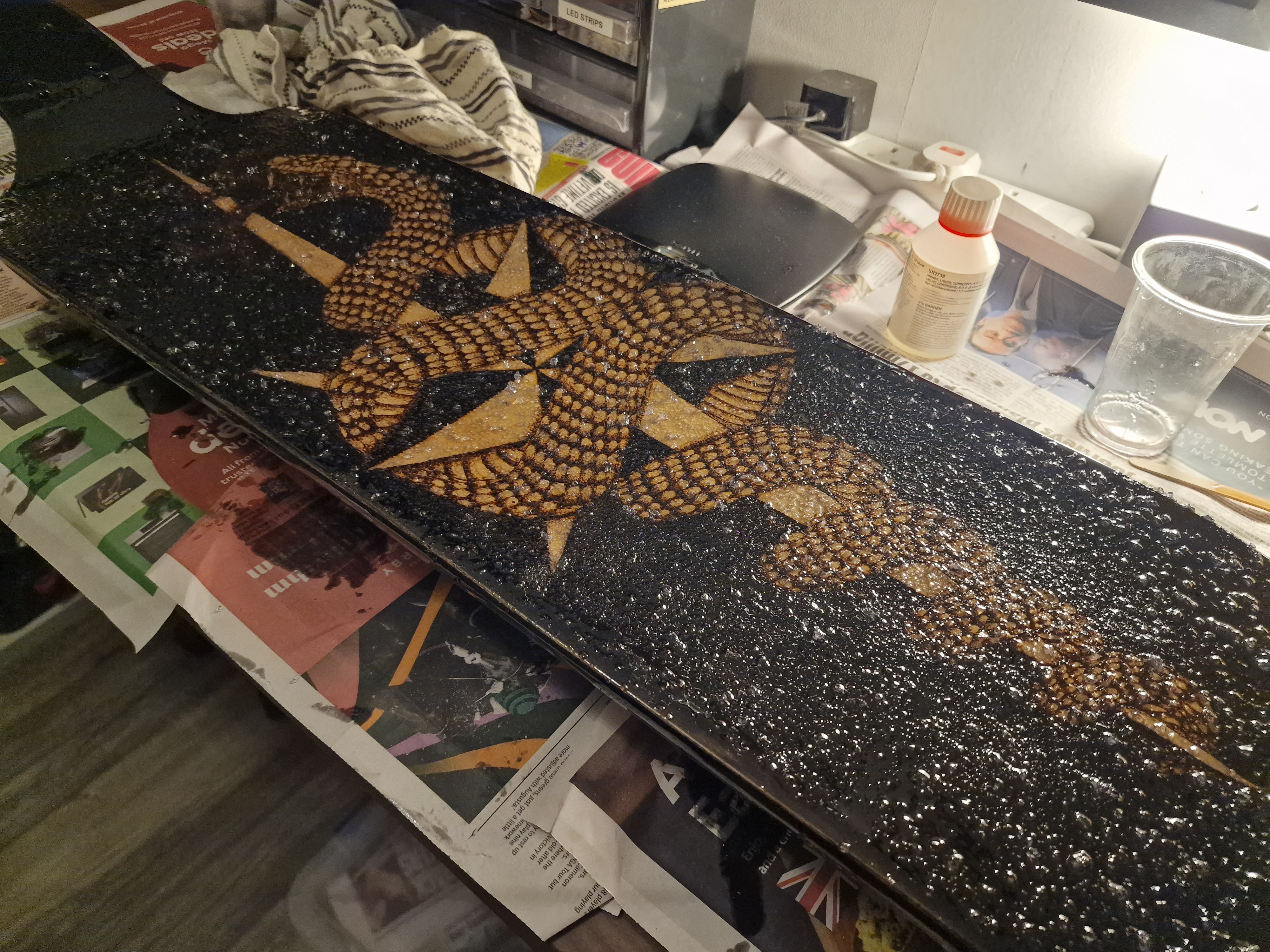
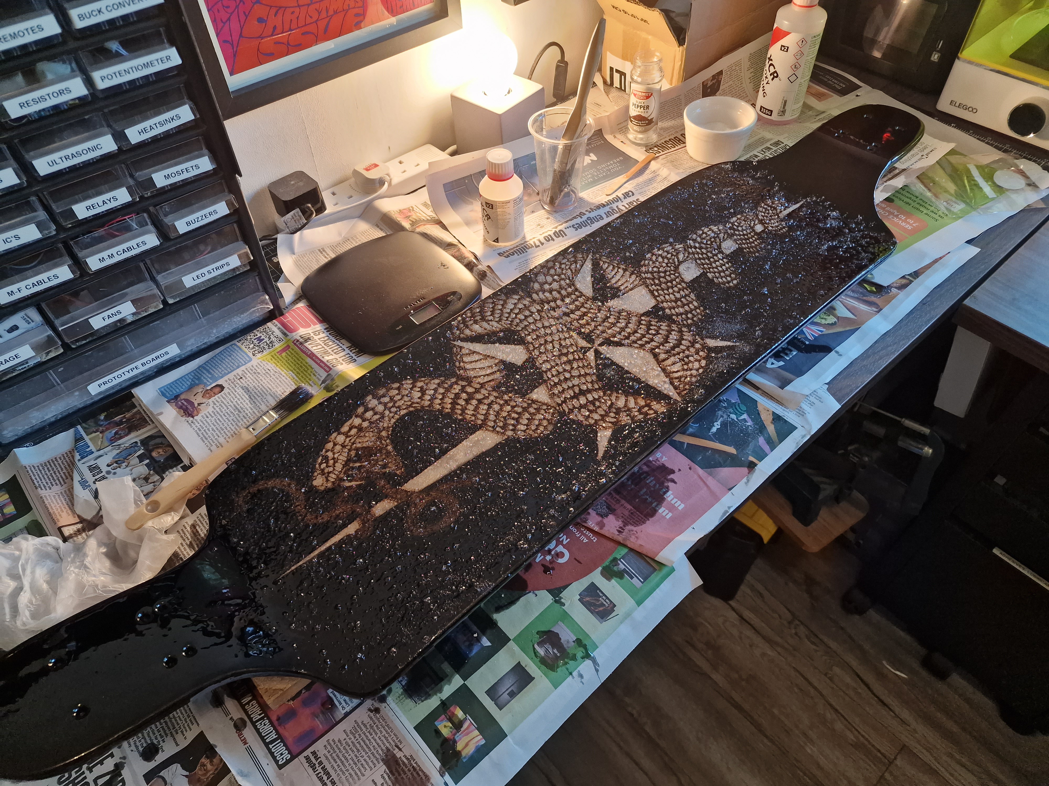
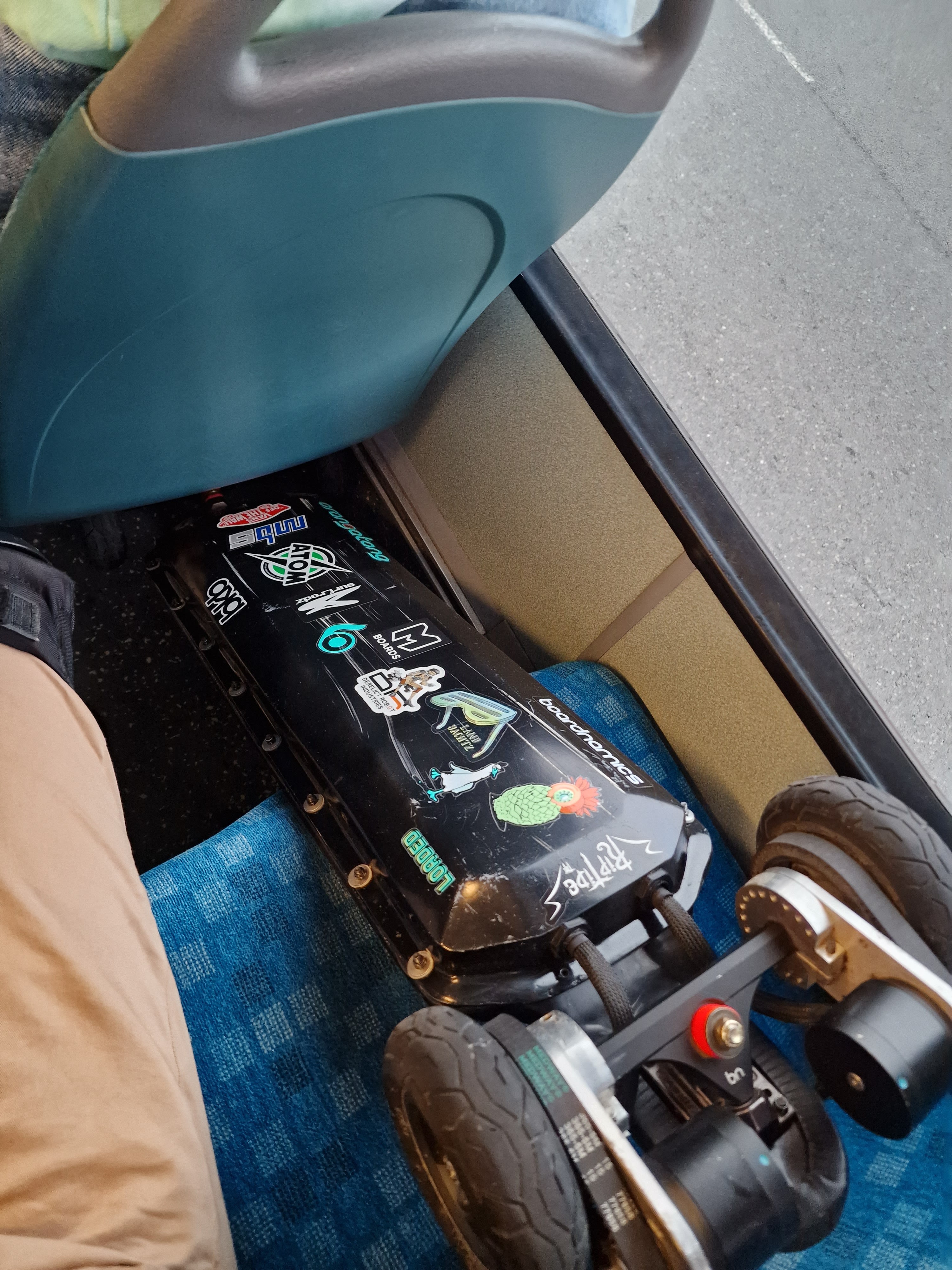
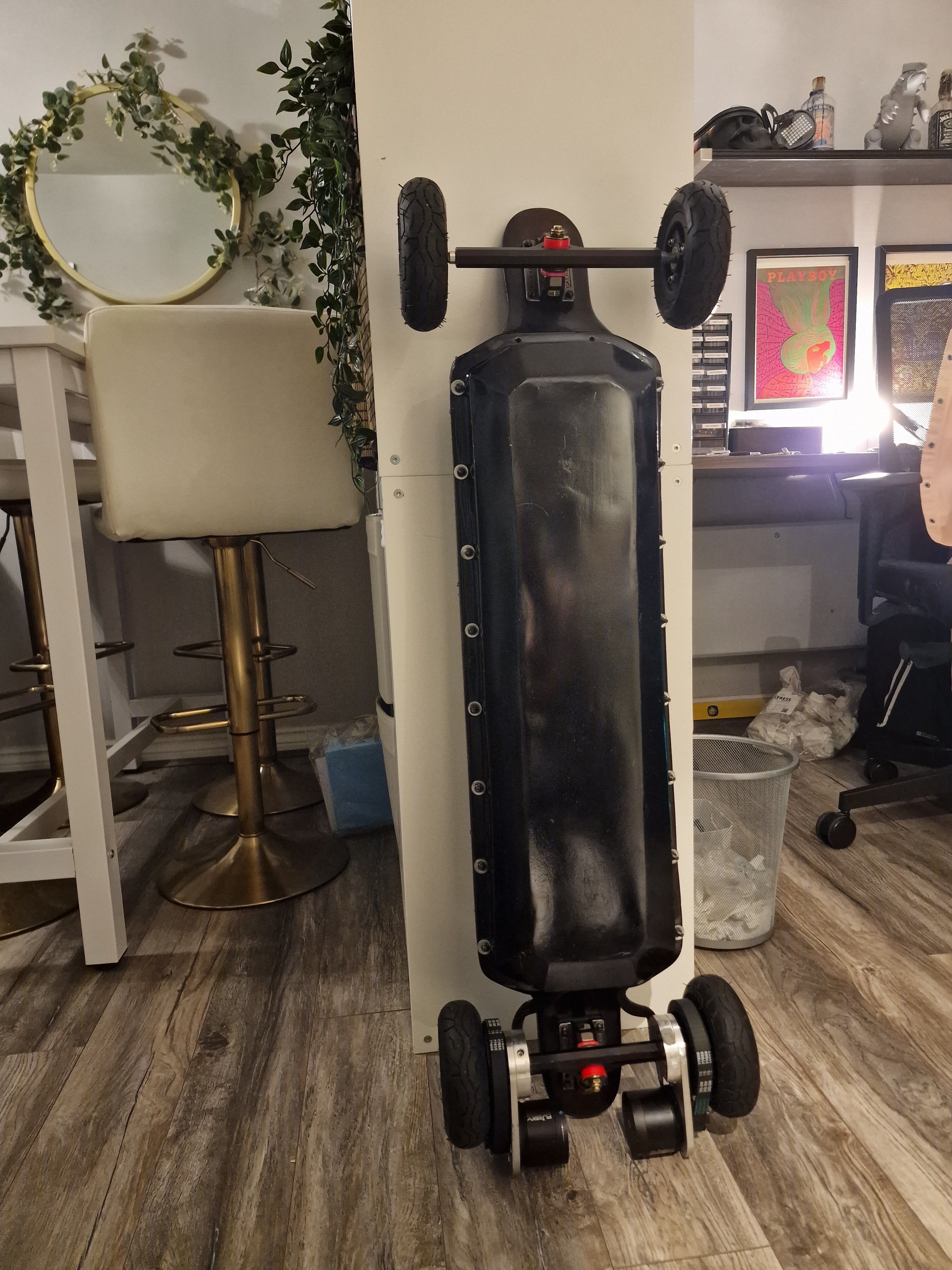
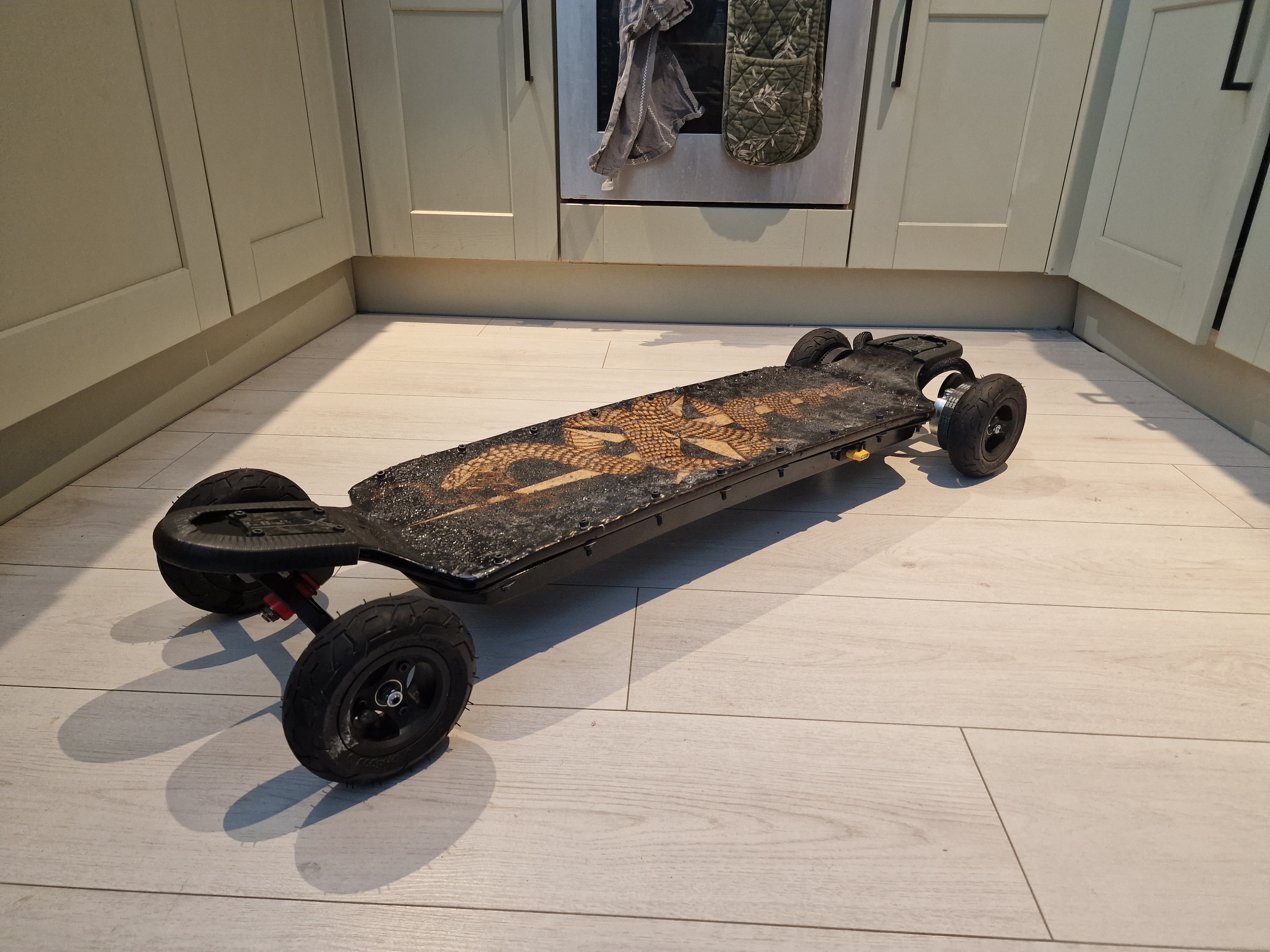
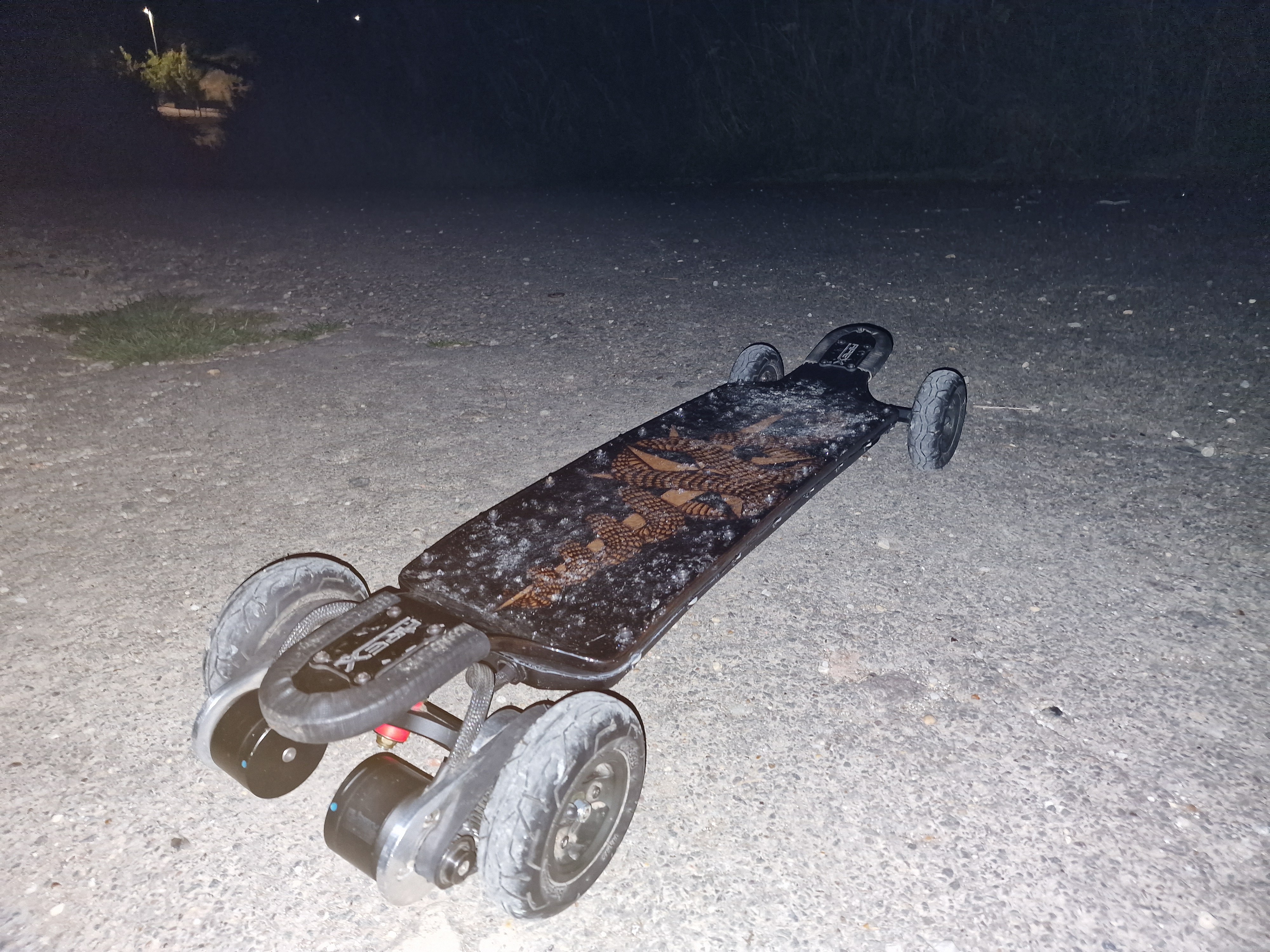
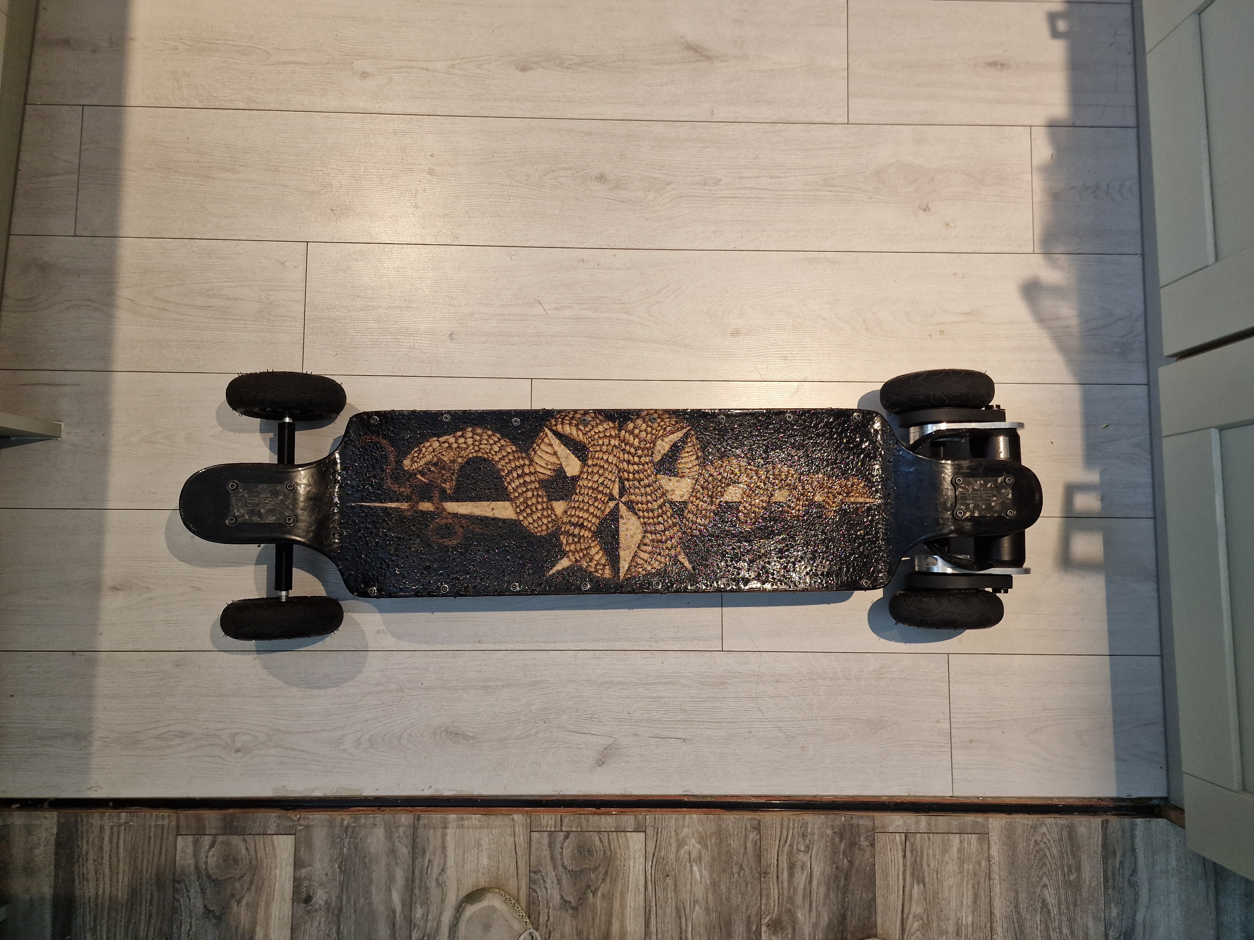
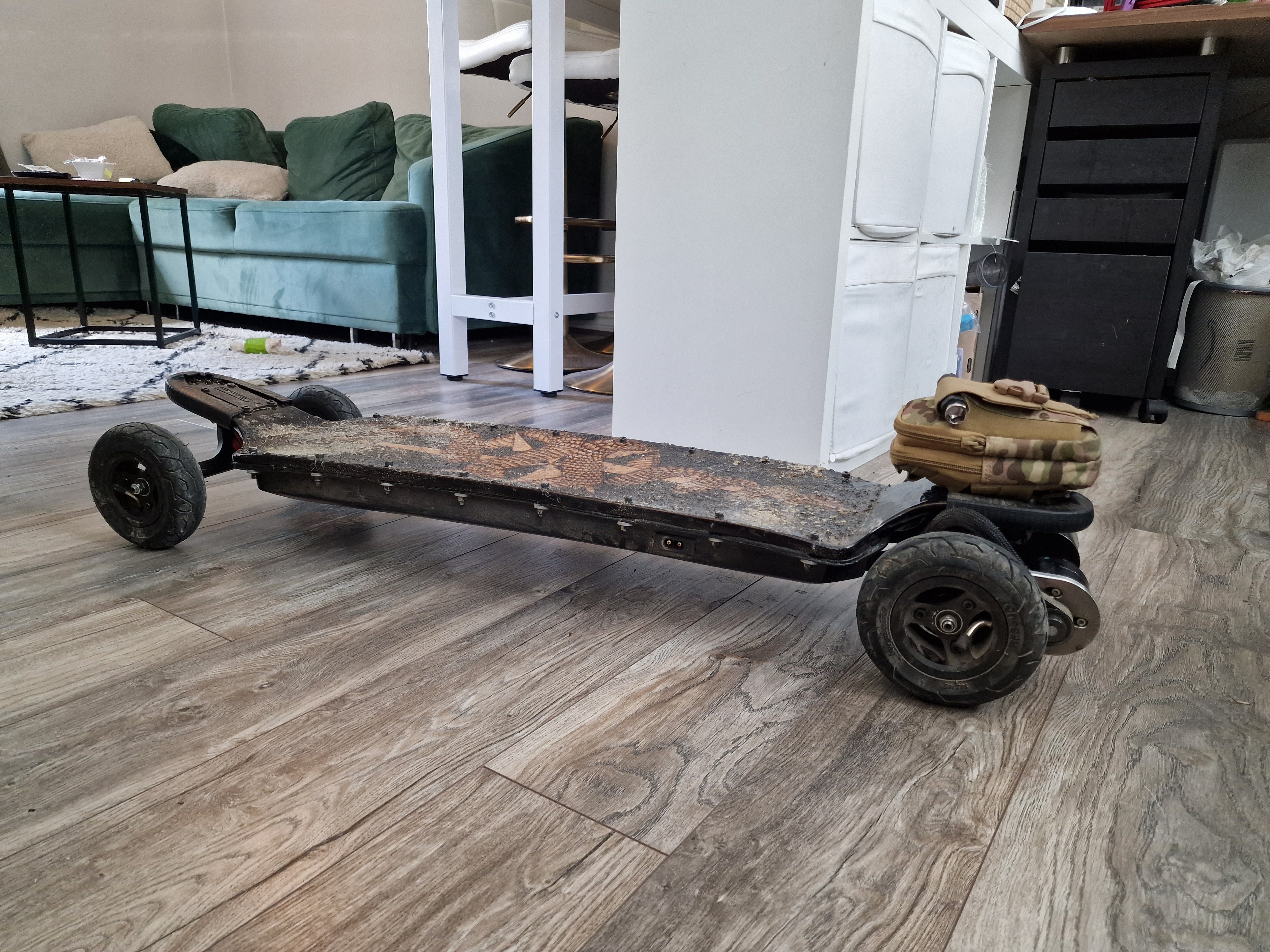
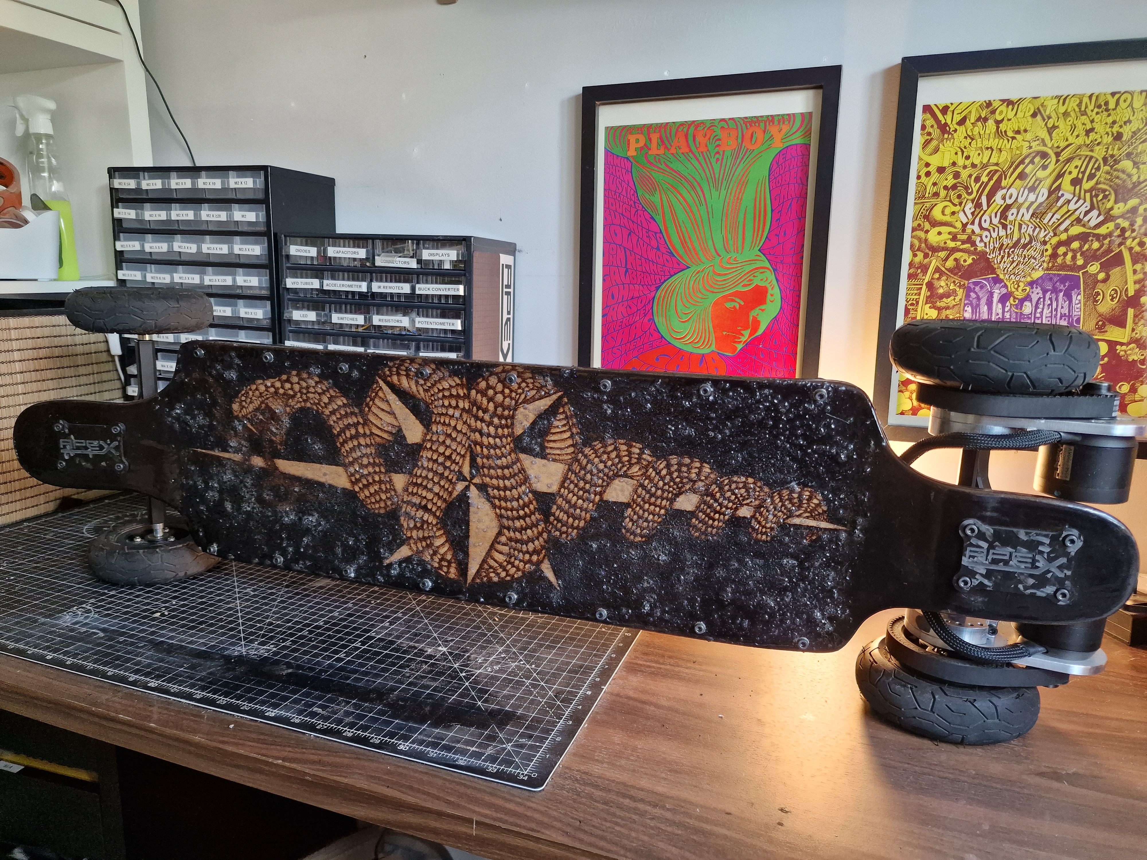
I'm not going to go into detail about the development process. I finished building Nagini in August 2023. Full in depth details of the build process can be found at the Esk8 forum. Instead, here are some photos (in no particular order).
The deck:
![]()
![]()
![]()
![]()
![]()
![]()
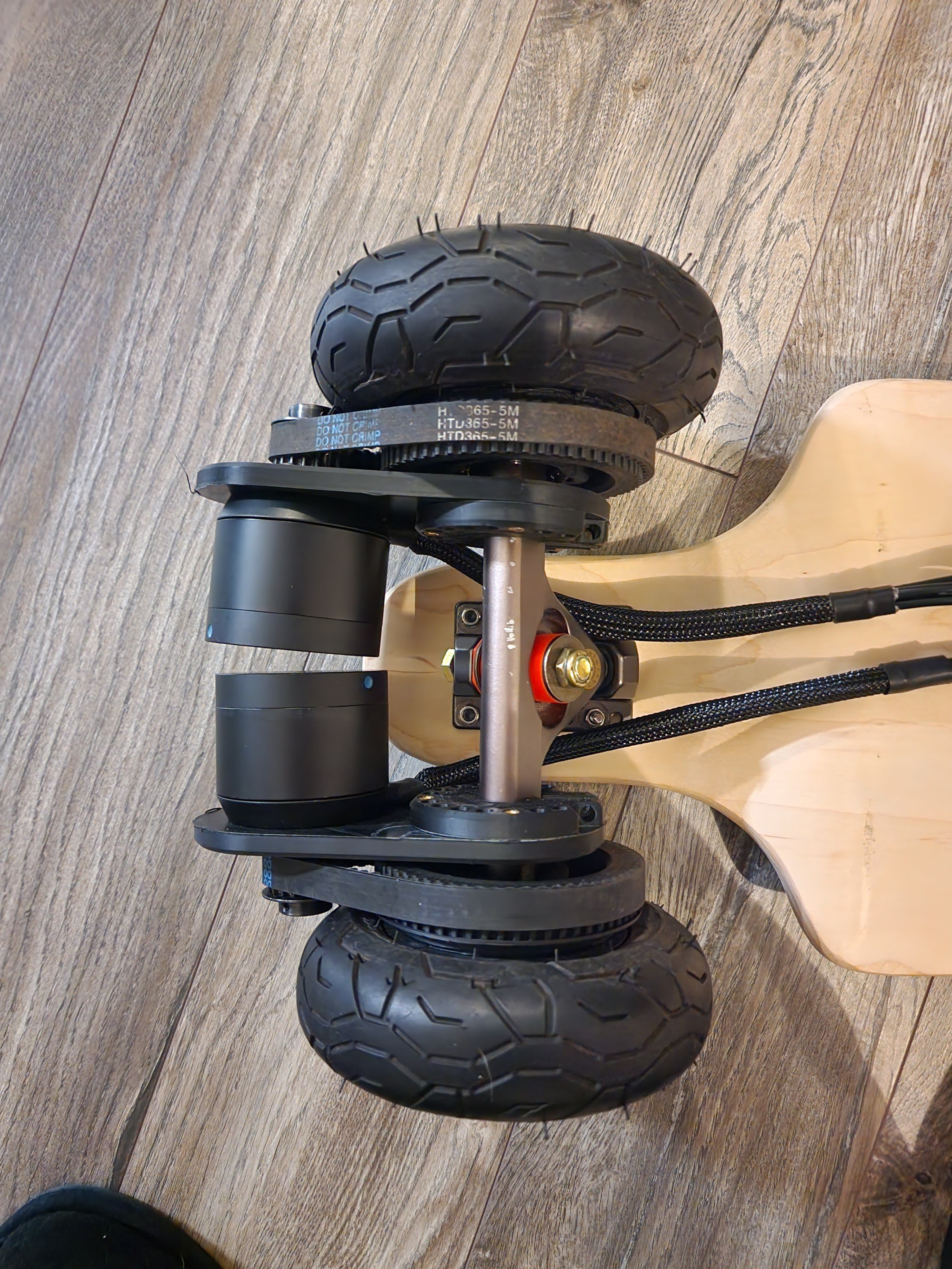
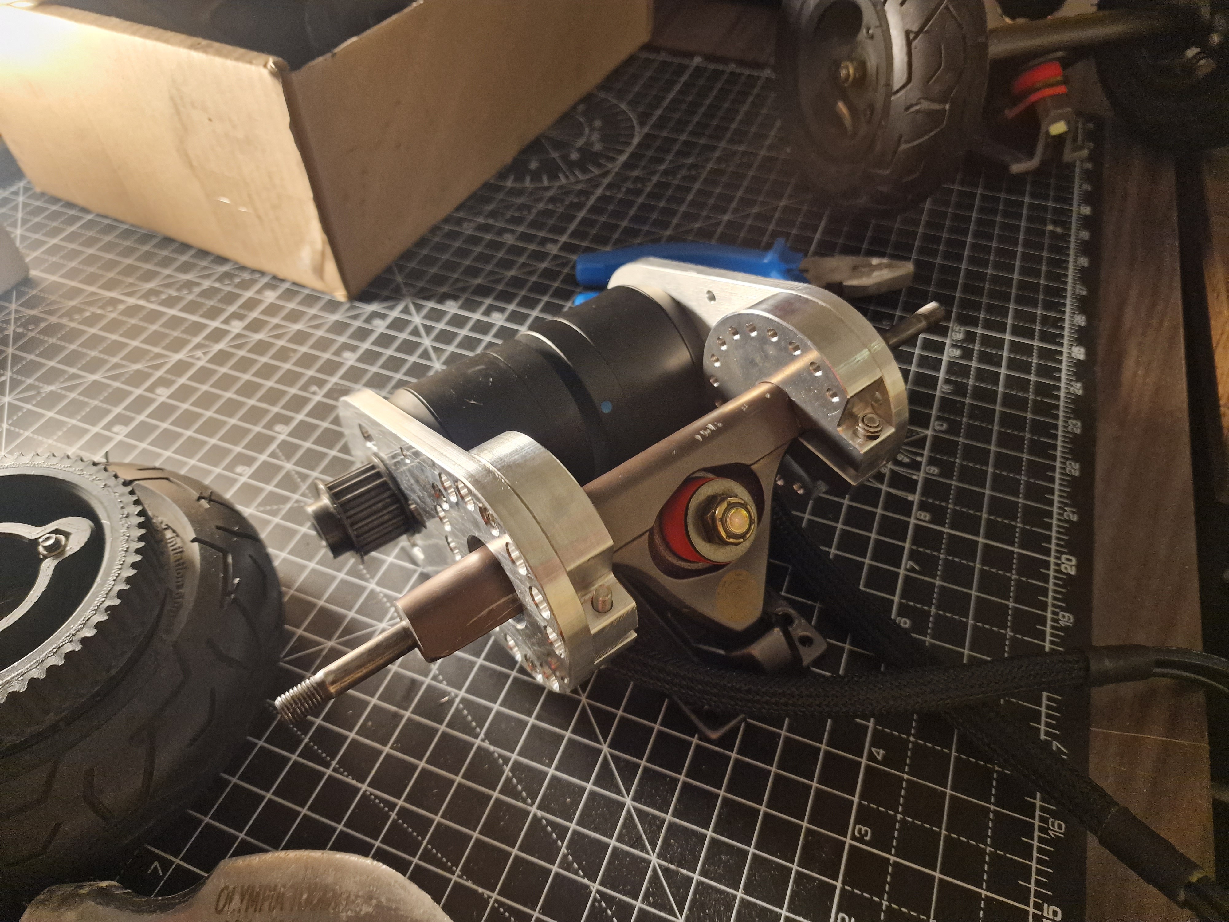
The motor mounts:
![]()
![]()
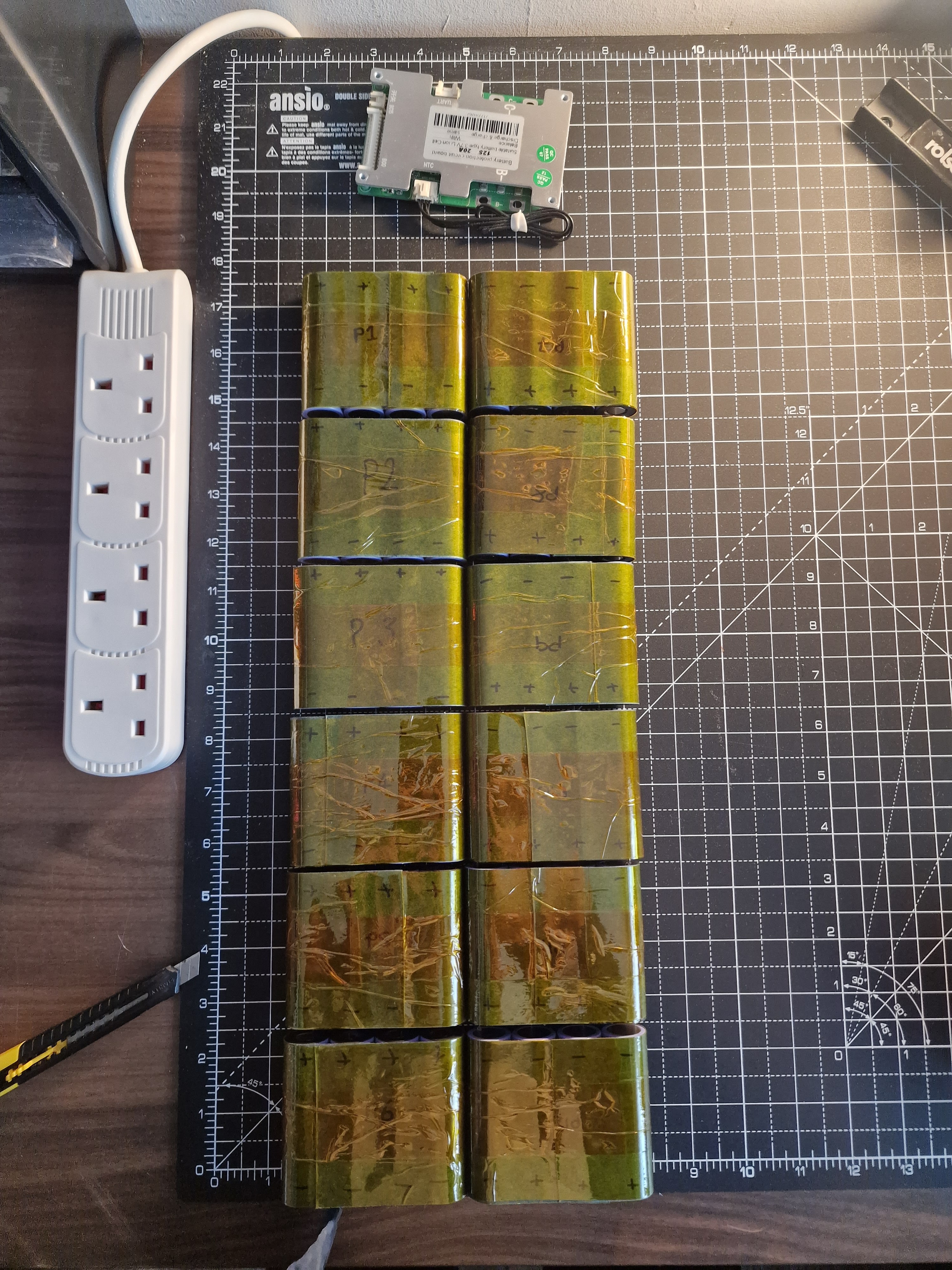
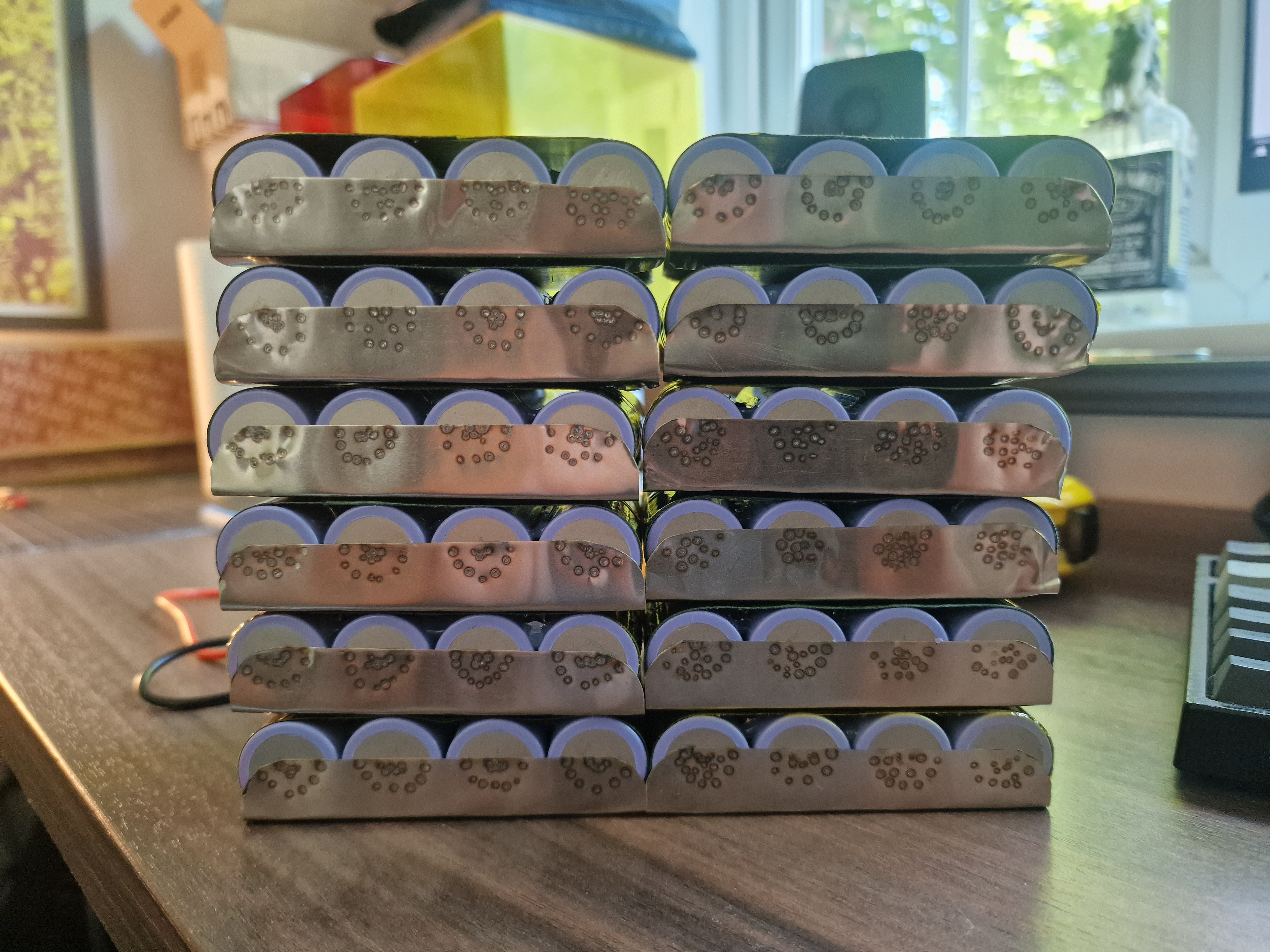
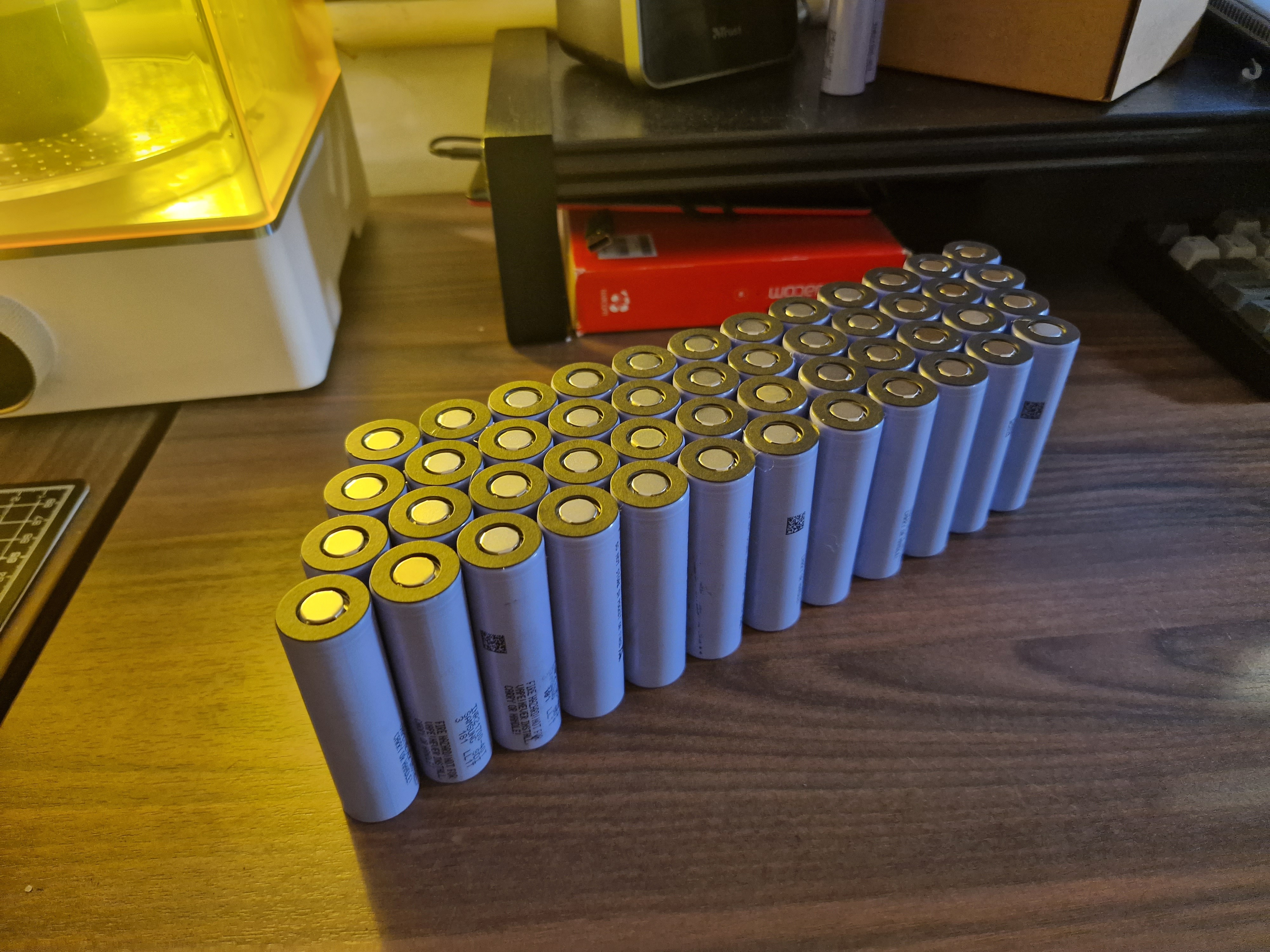
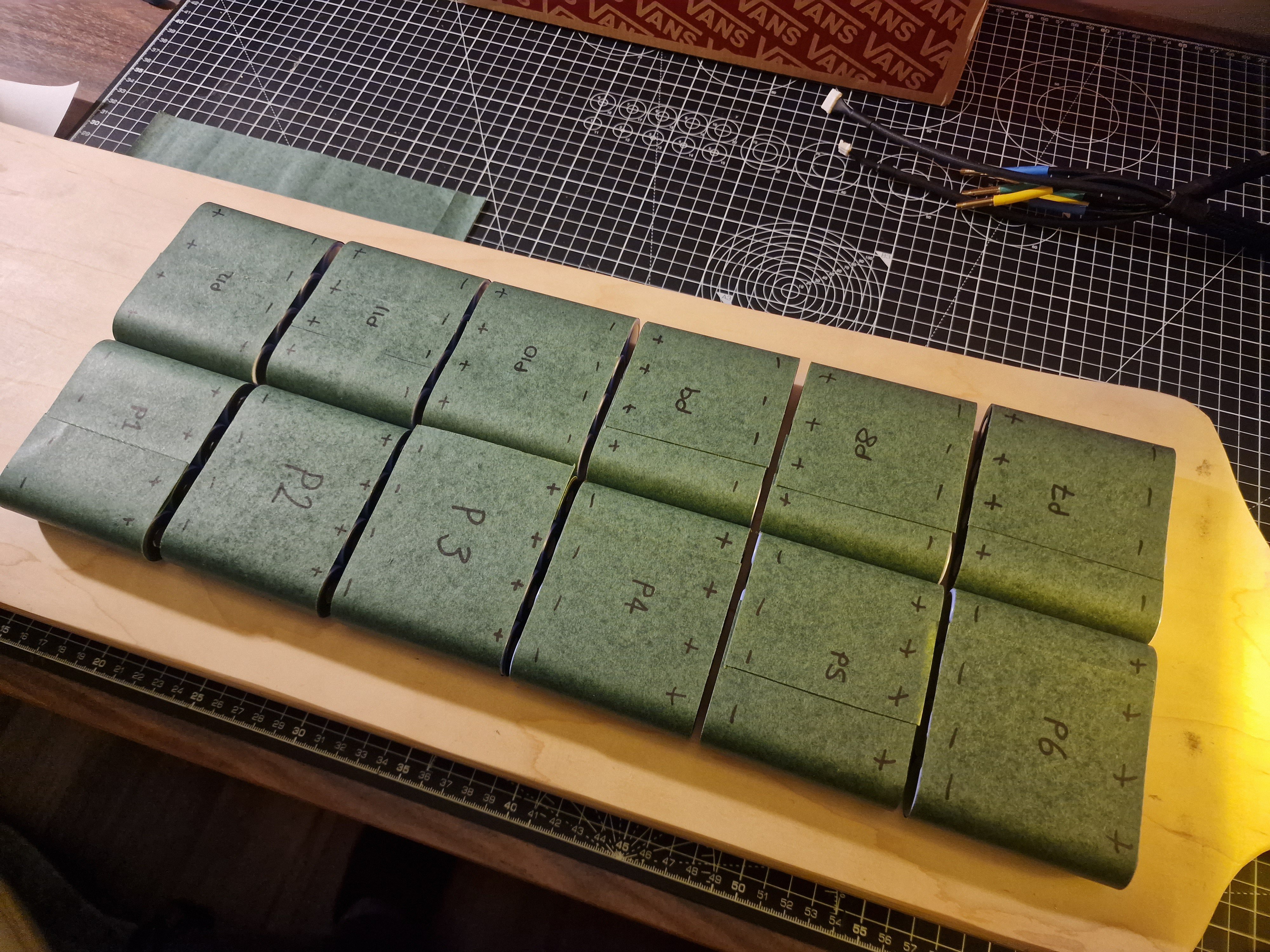
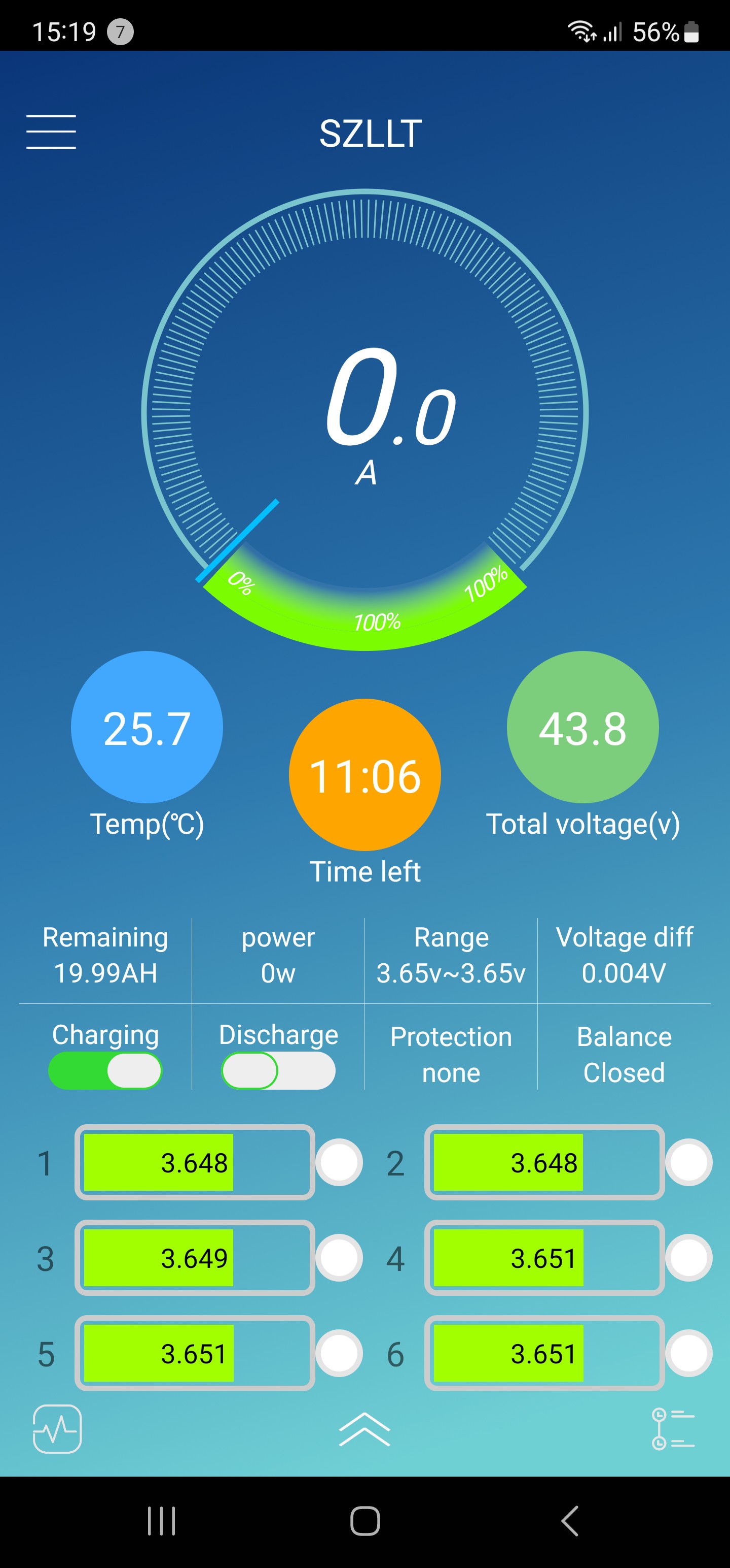
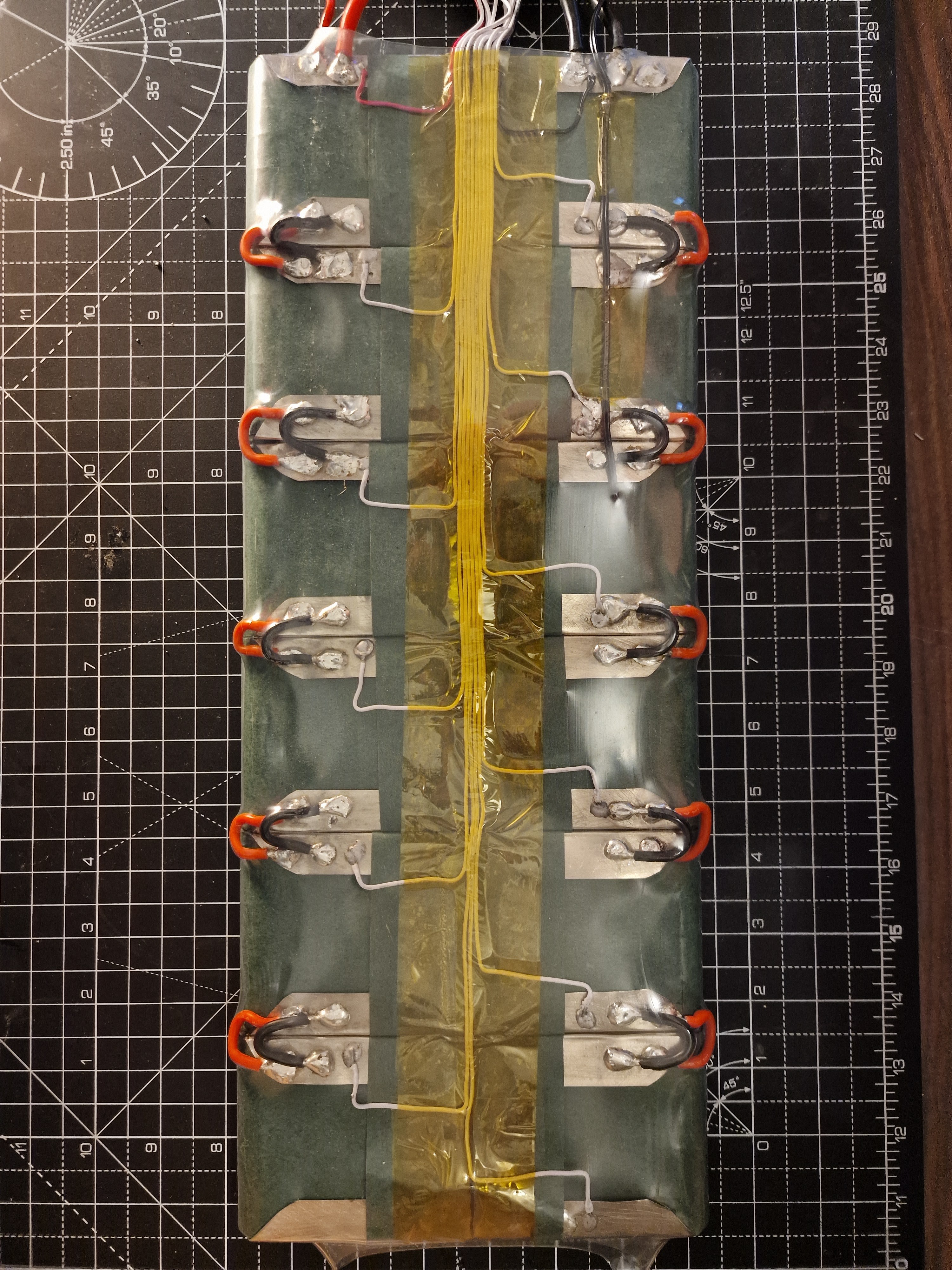
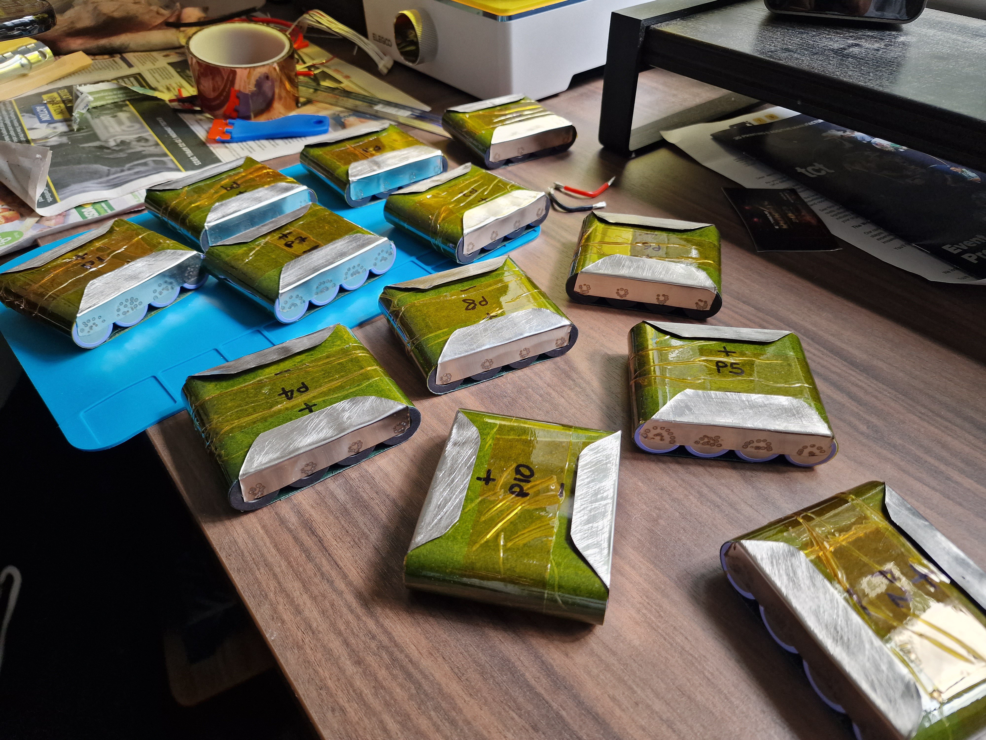
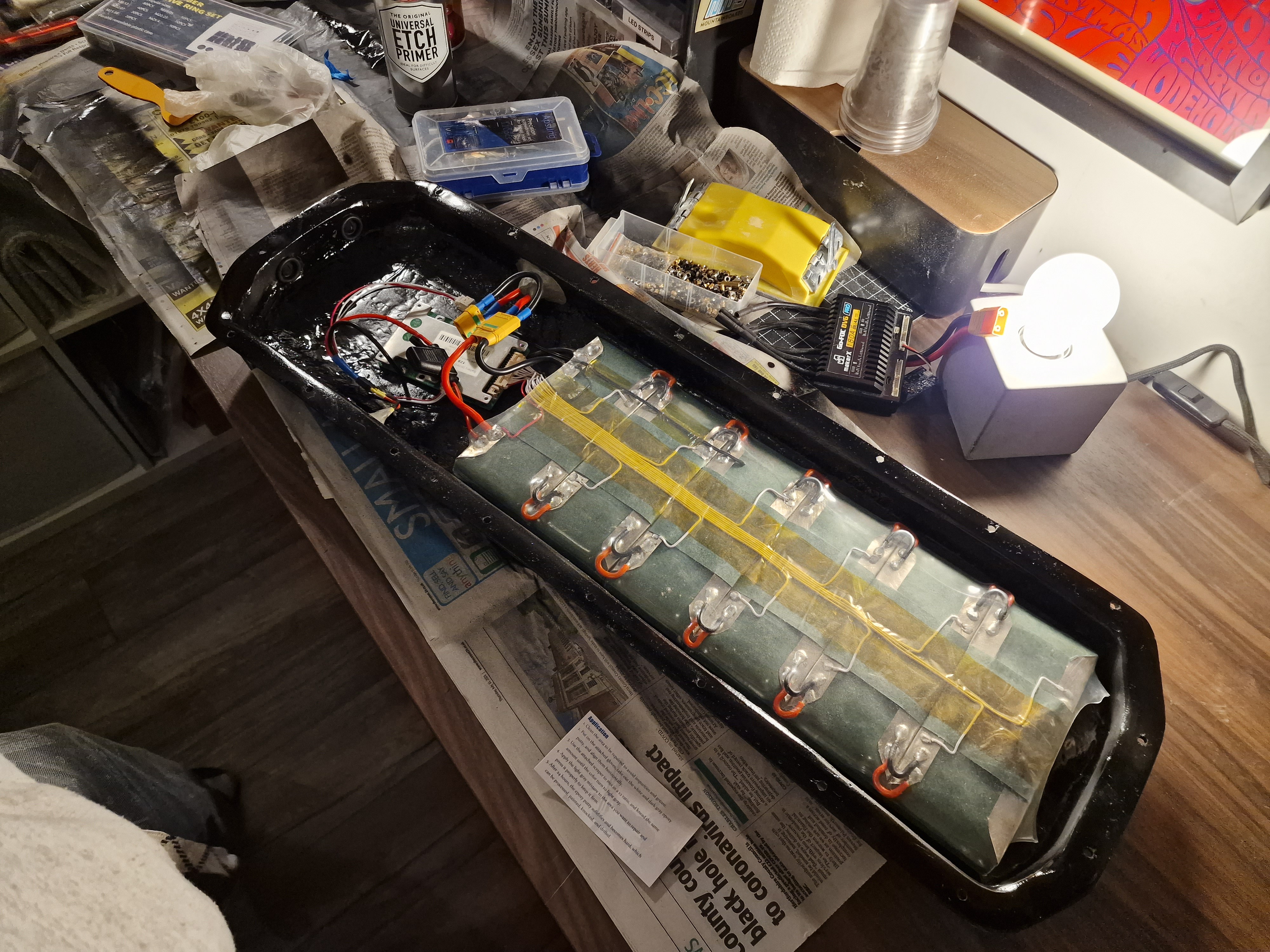
The battery:
![]()
![]()
![]()
![]()
![]()
![]()
![]()
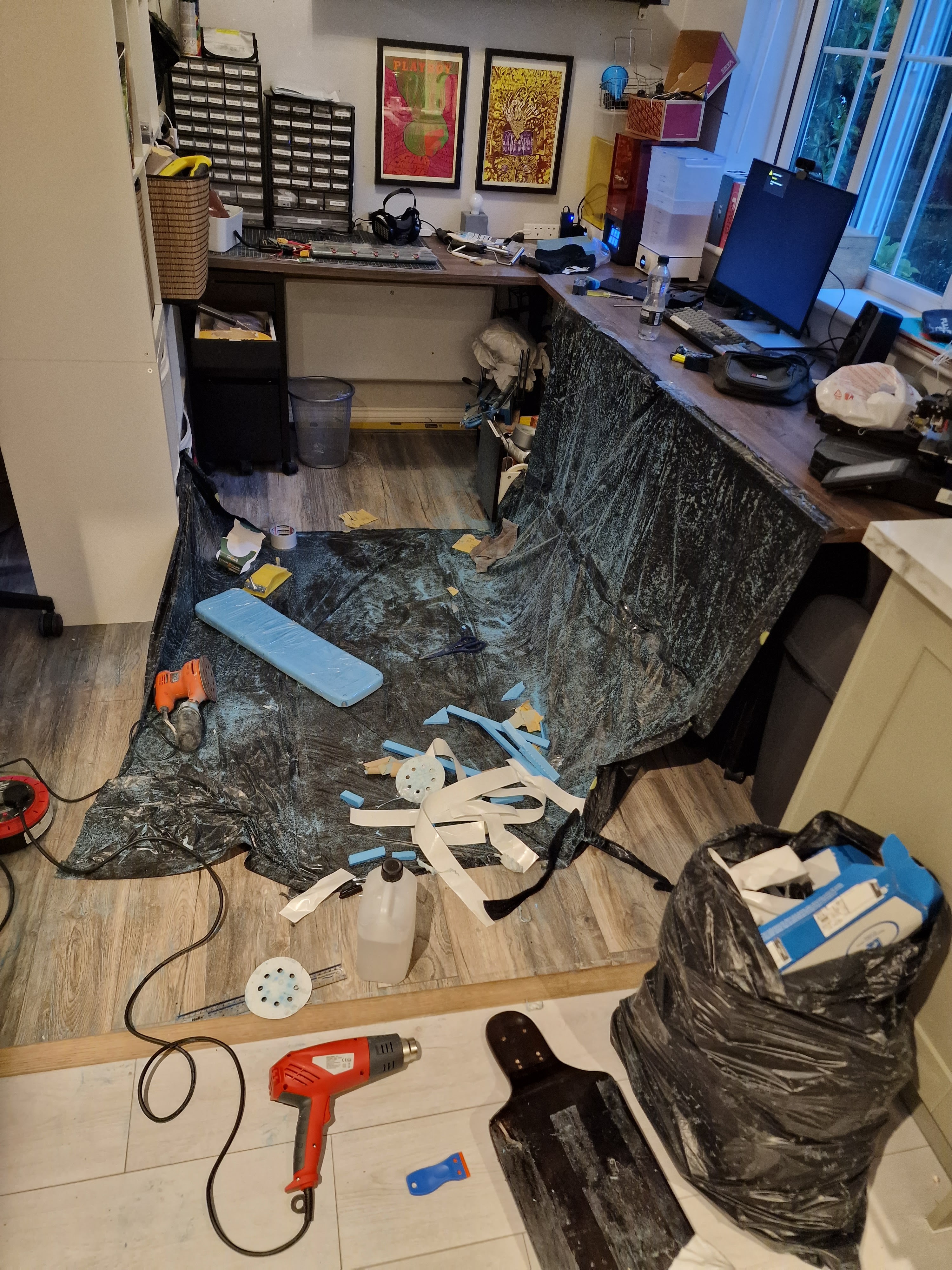
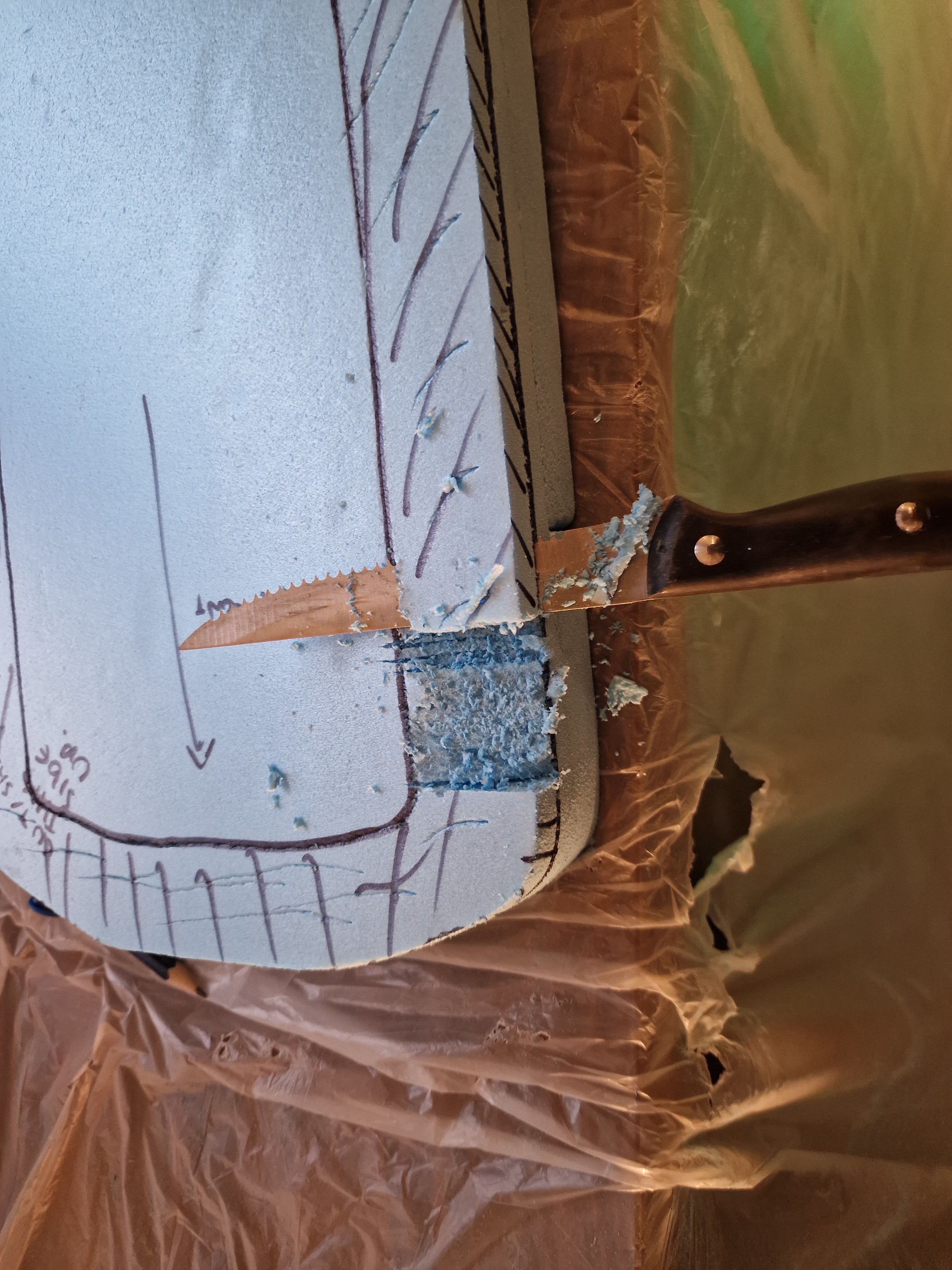
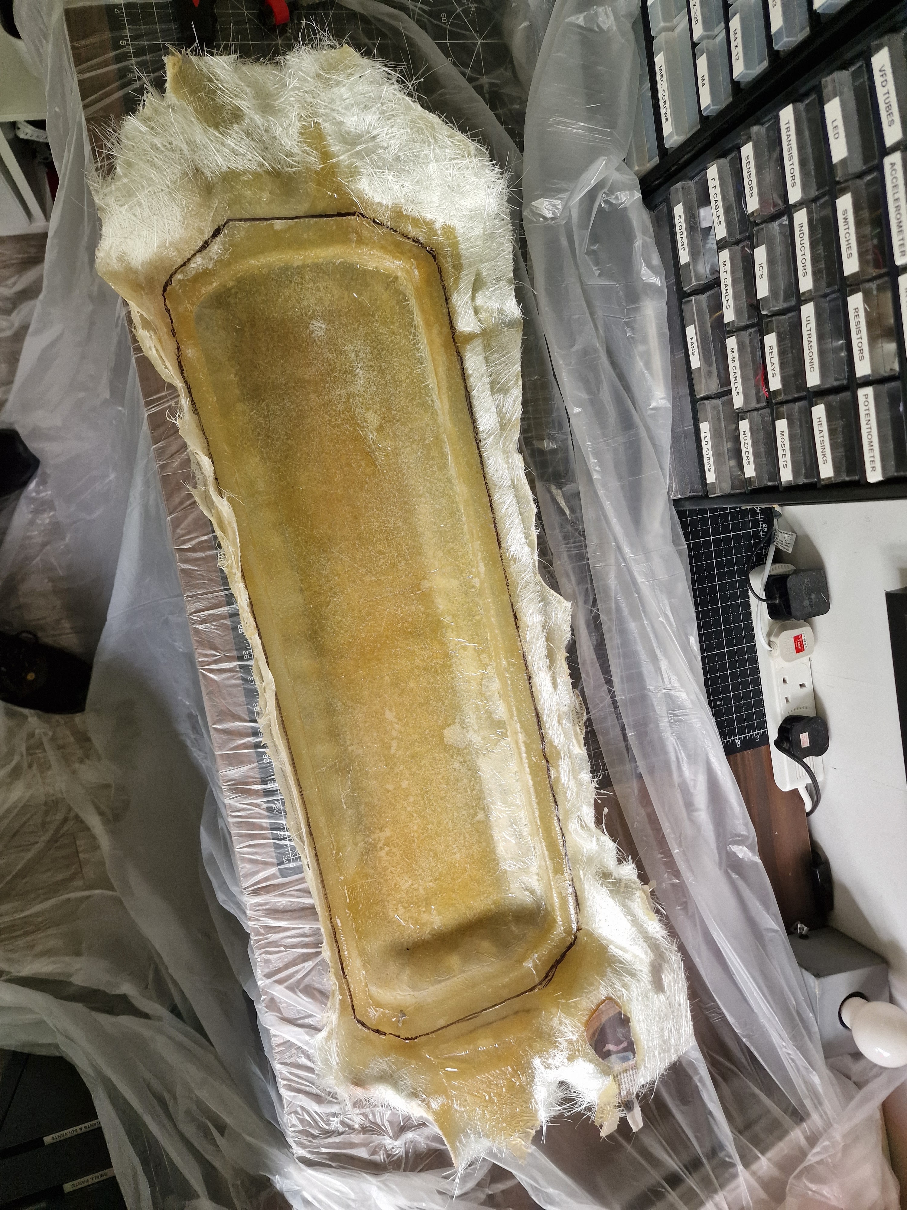
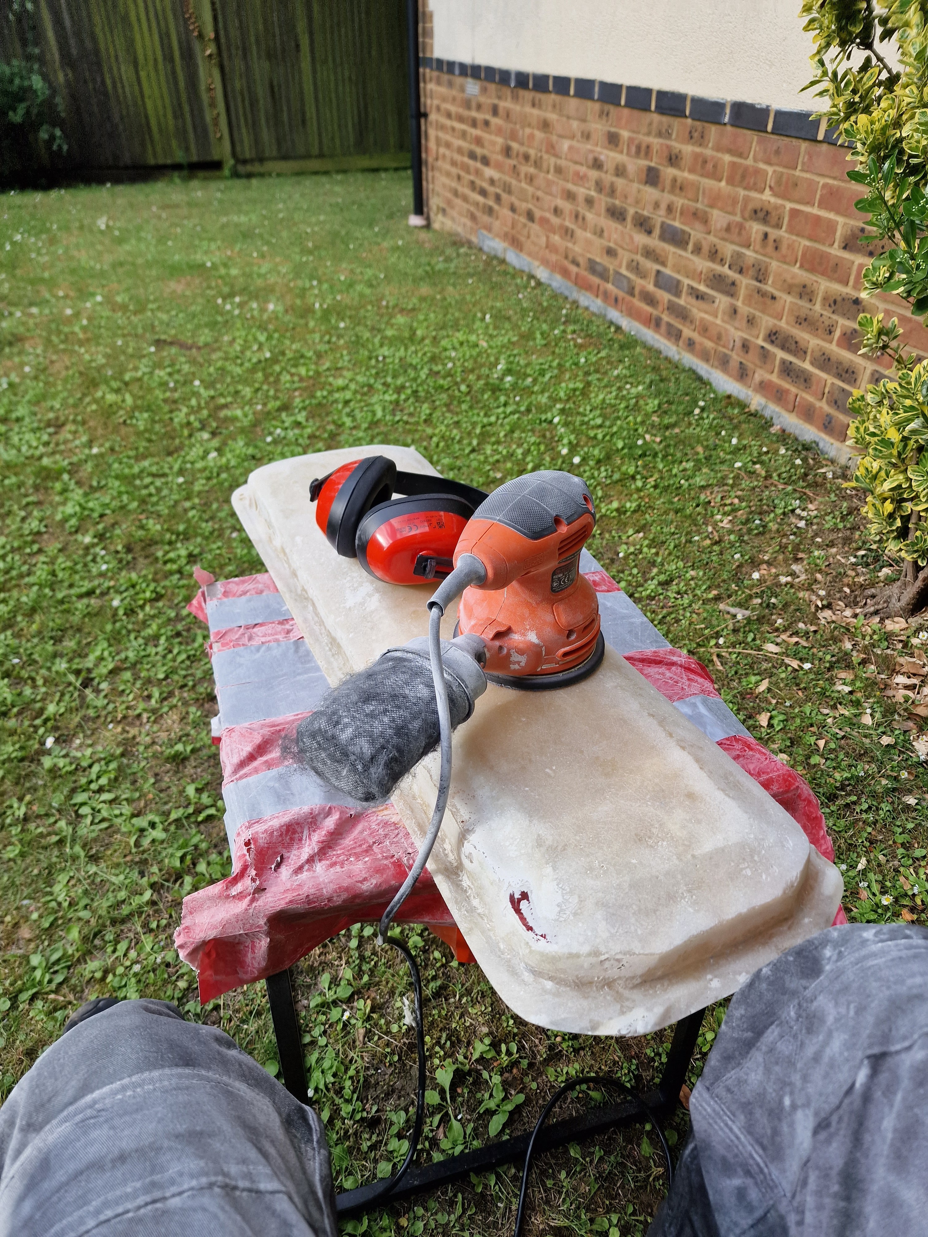
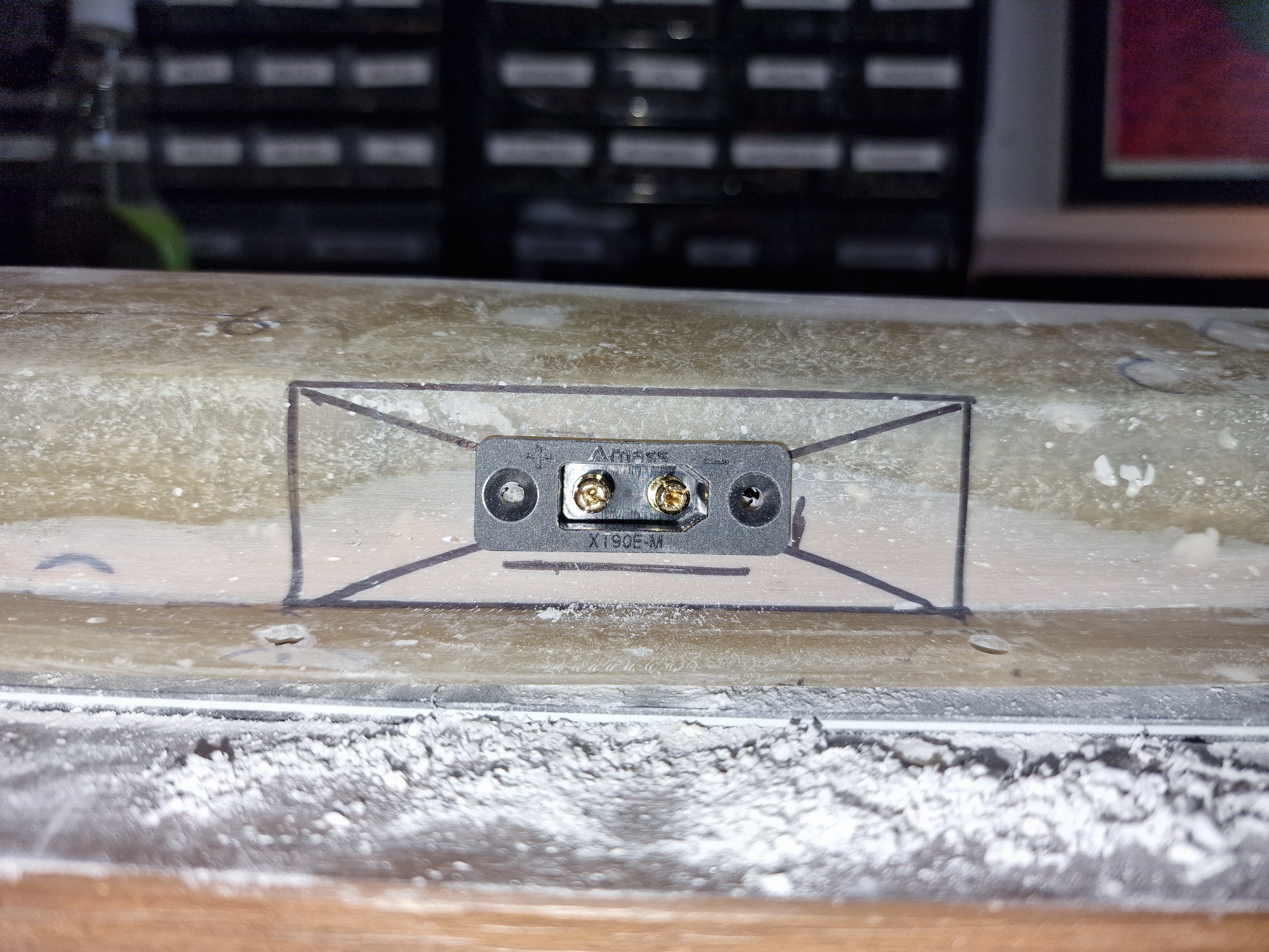
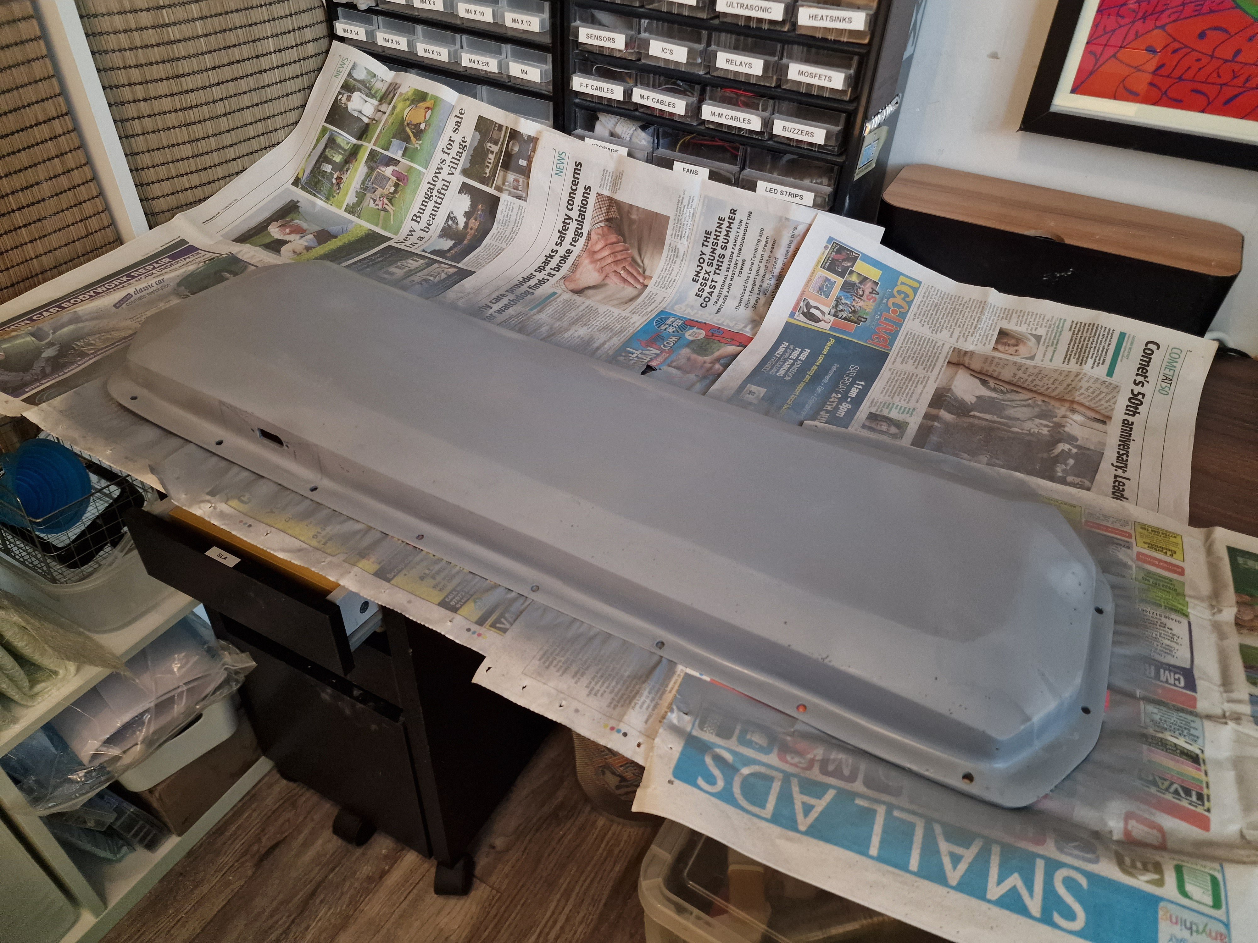
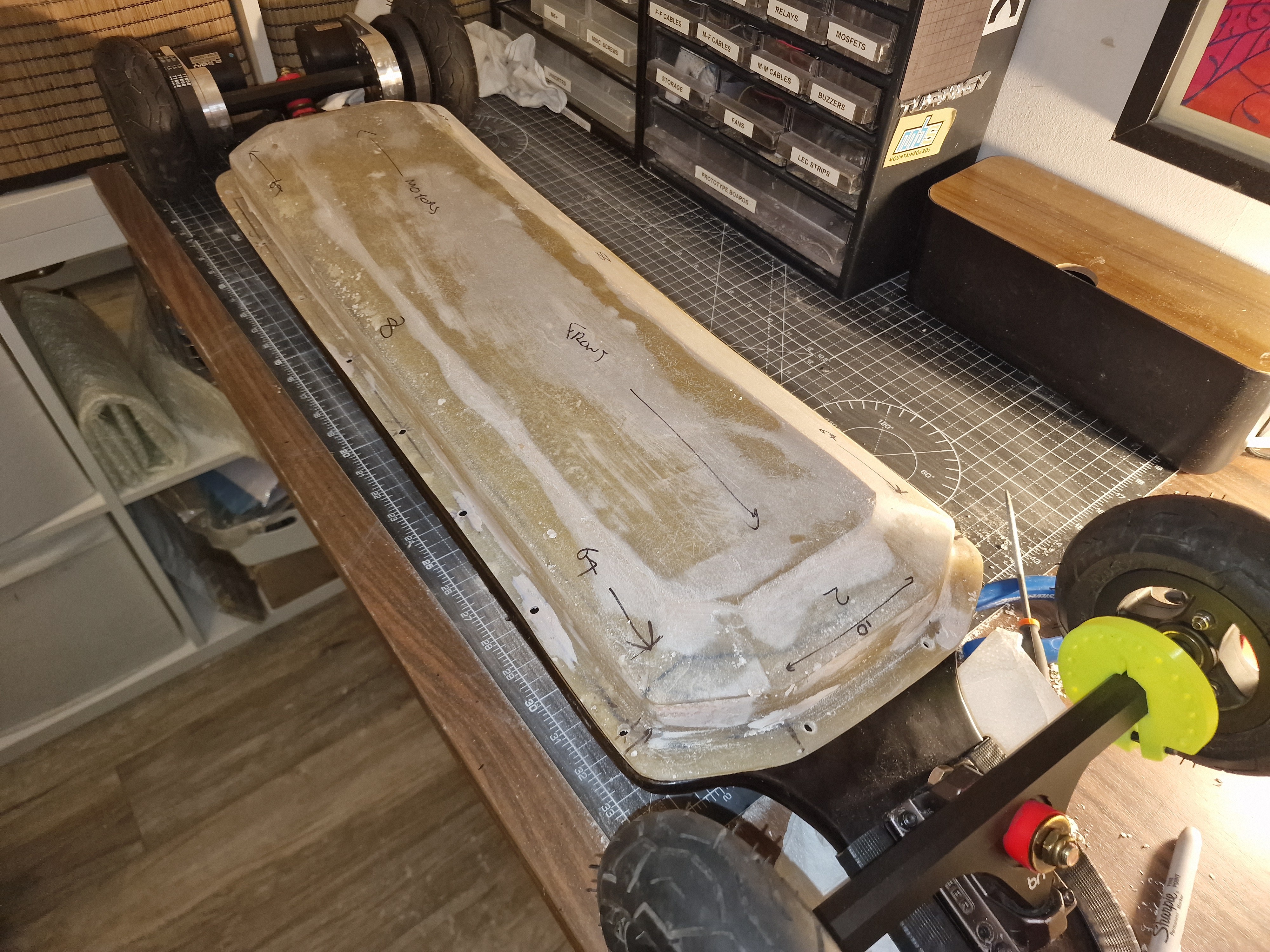
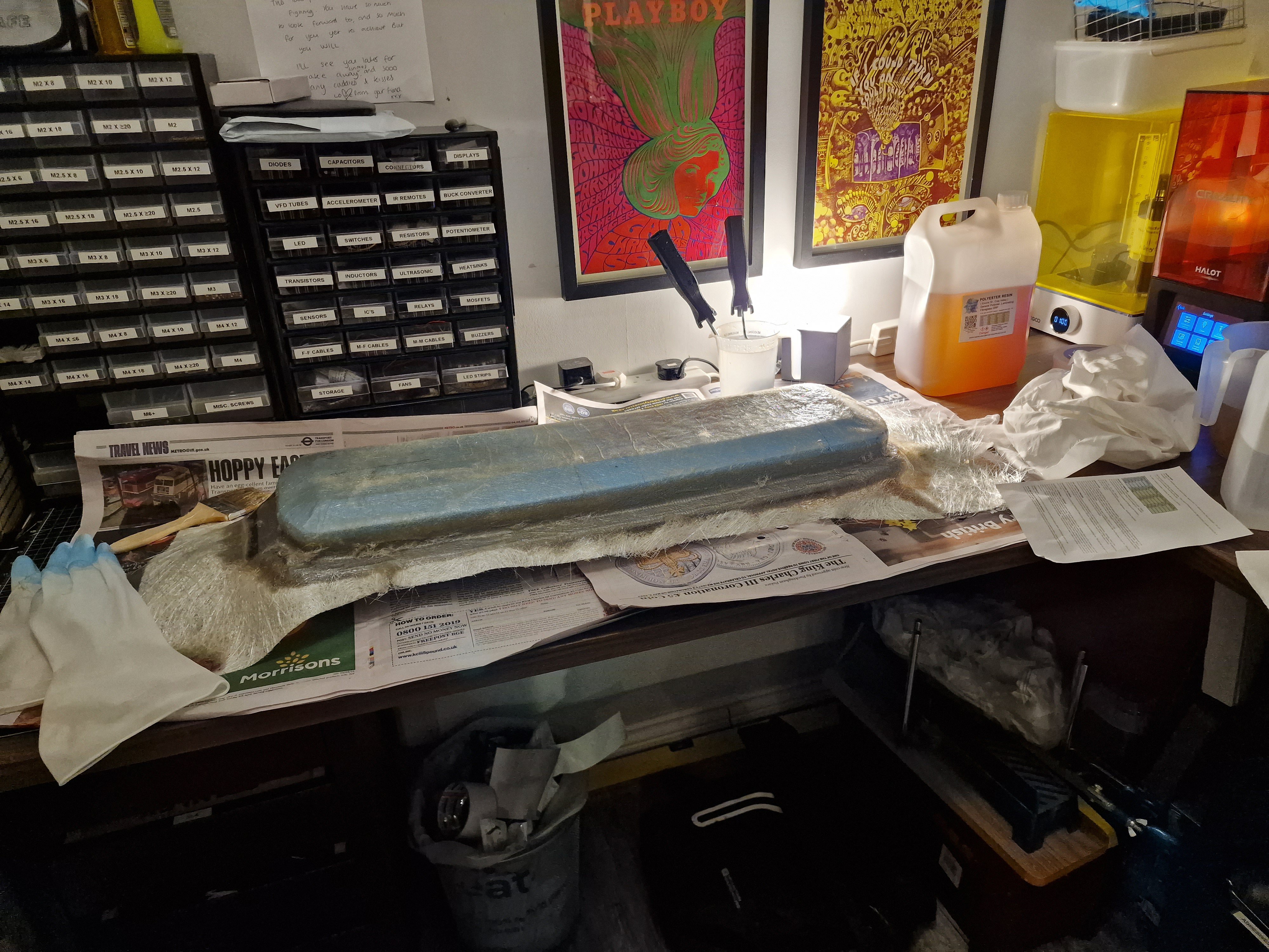
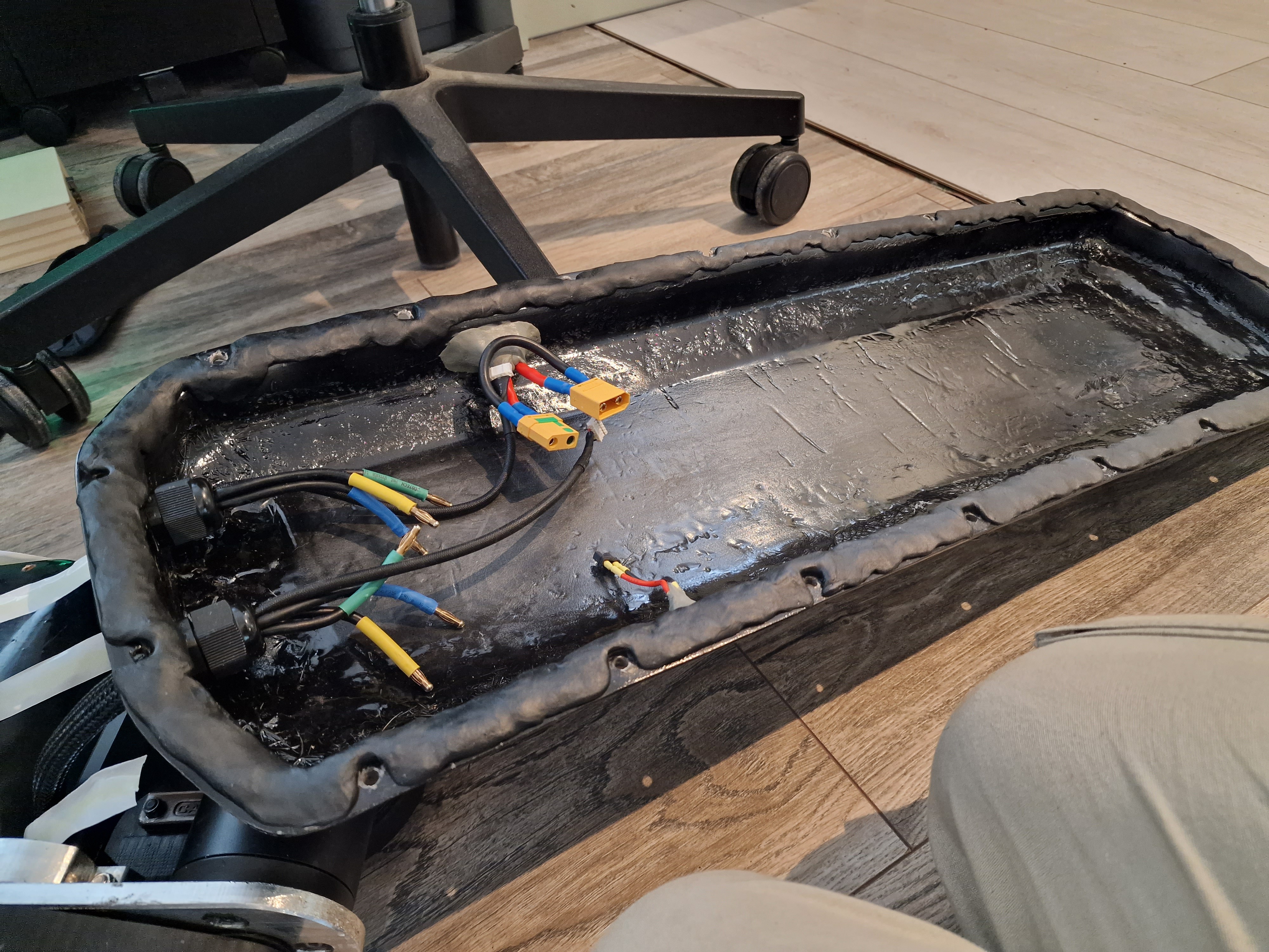
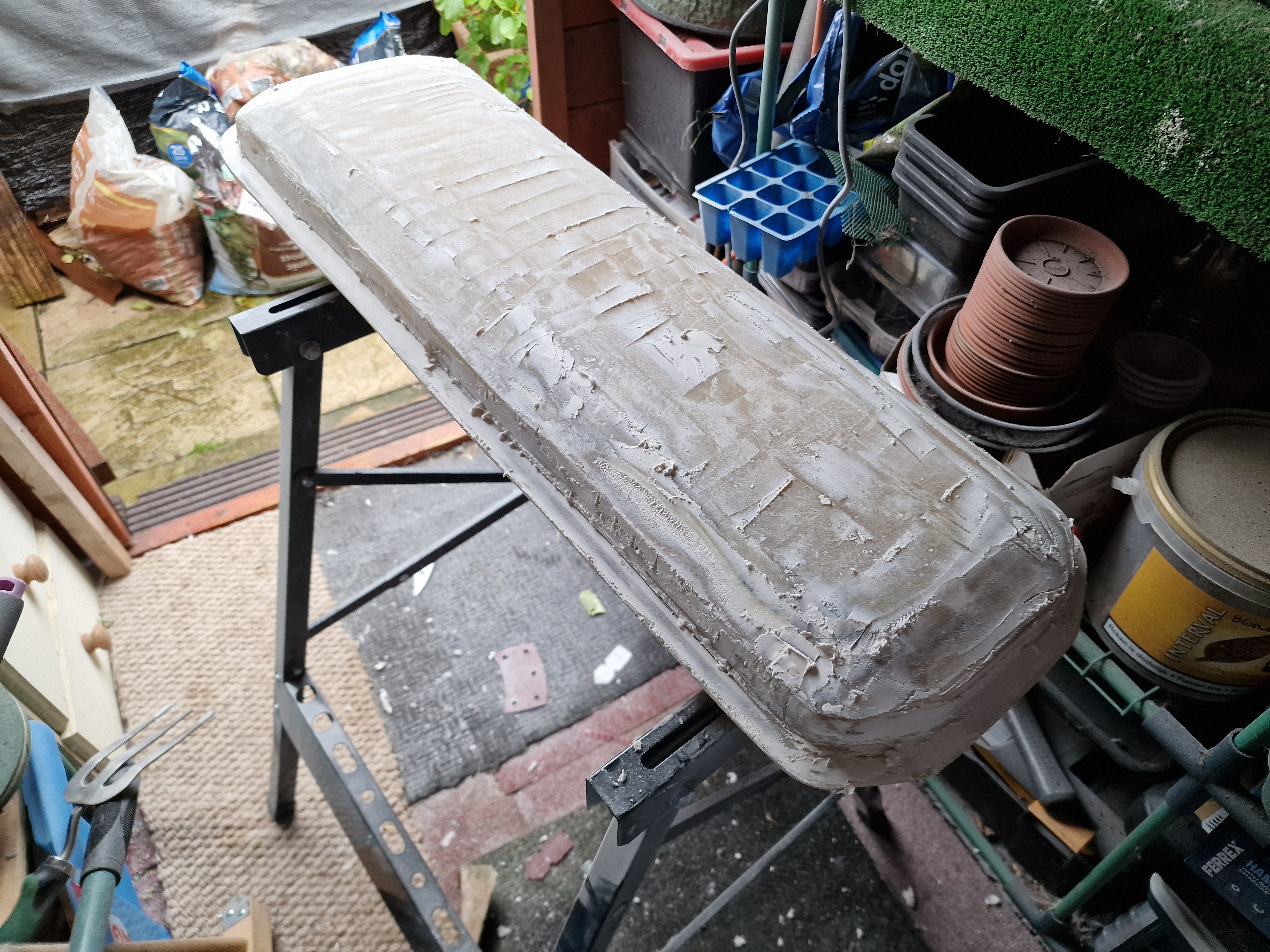
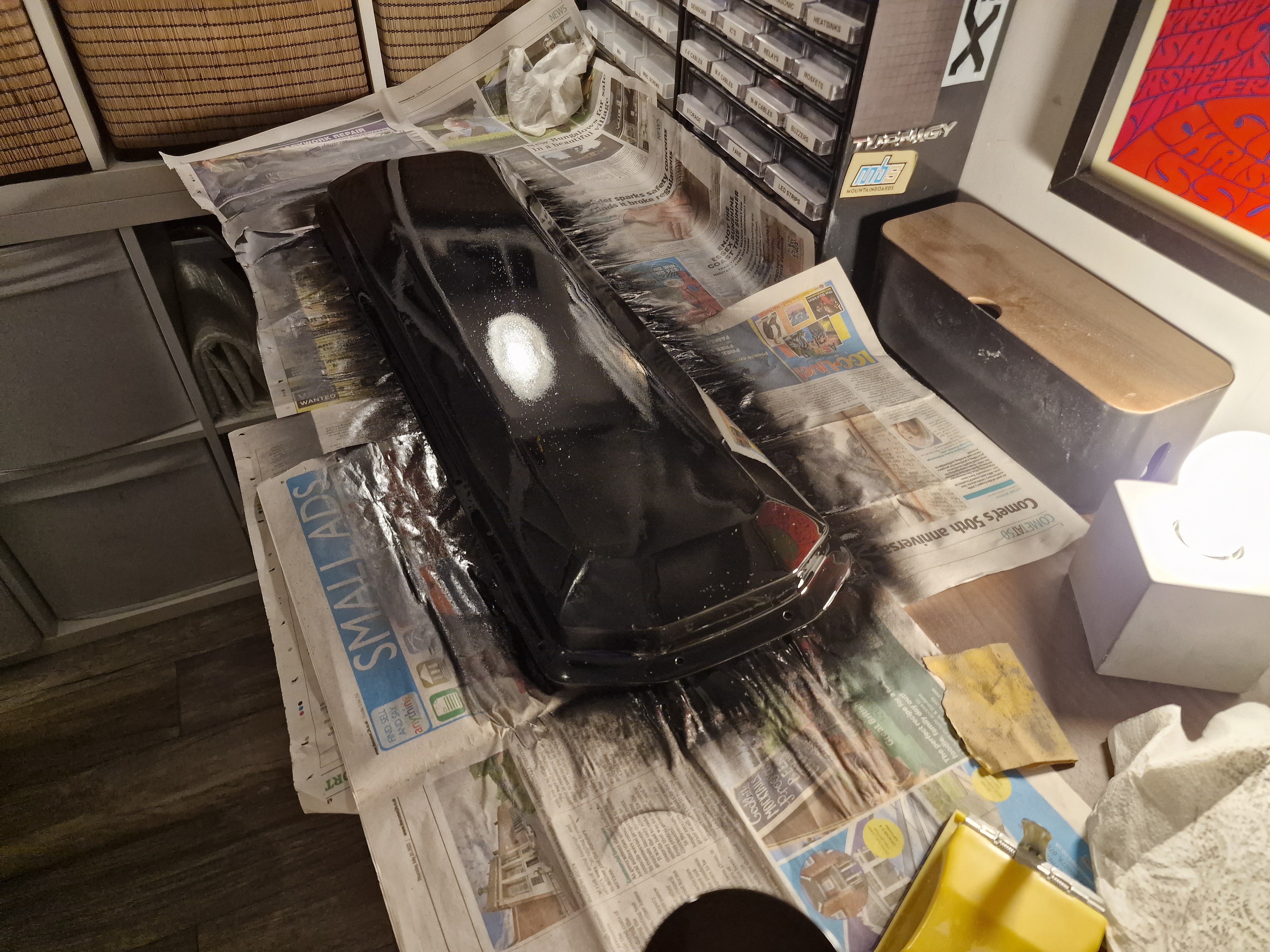
The enclosure (this was a nightmare)
![]()
![]()
![]()
![]()
![]()
![]()
![]()
![]()
![]()
![]()
![]()
![]()
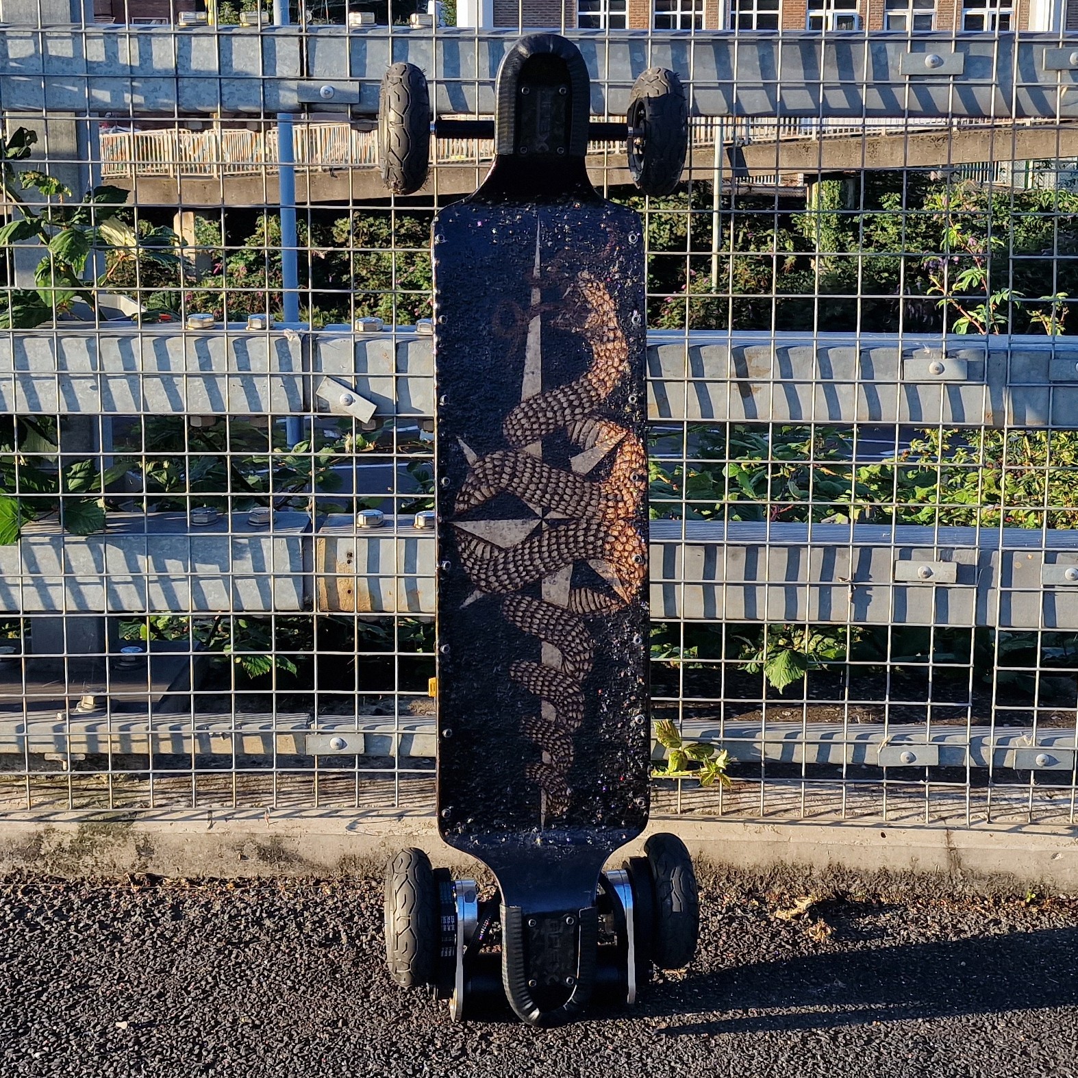
The final product:
![]()
![]()
![]()
![]()
![]()
![]()
![]()
![]()
If you have any questions about the build process, please feel free to get in touch. There is still some work to be done - the motor mounts need redesigning, the enclosure needs improved waterproofing, and I would eventually like to add some lights to the board.
-
Motor Mount Design
09/26/2022 at 11:23 • 0 commentsCaliber Profile
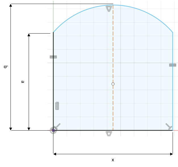
The caliber hanger profile is a rectangle, with one rounded edge. Sounds simple right? All I need to do is take some measurements.
Unfortunately, not all trucks are built the same. Since I don't have access to the technical drawings for the caliber trucks, I cannot tell the tolerances on the hanger dimensions so I will take reference from a few sources.
Also, the profile appears to be thicker towards the centre than at each end, so I need to take this into account too.
Source a (mm) b (mm) x (mm) Front truck left 14.0 18.8 18.0 Front truck right 14.0 19.2 18.0 Rear truck left 13.8 19.0 18.0 Rear truck right 14.3 19.3 18.2 ESK8 forum post 16.6 20.7 18.2 GrabCAD 15.2 19.8 17.8 The inconsistencies in my measurements may be explained not just by manufacturing variations, but also from measuring at different points along the hanger.
I have assumed that Caliber II trucks have the same profile as Caliber III trucks, but what's interesting is that the two Caliber II sources have a value of a which is 1.4 - 2.8 mm longer. The width of the profile, i.e. x, seems to be consistent at around 18 mm, and the height, b, varies within a 1.9 mm range.
I could validate my results by asking other caliber truck owners to measure their hanger profiles, or even by contacting the manufacturers themselves to find out, however I'm impatient and this is just a hobby project so this should suffice.
I will proceed with the following nominal dimensions:
a (mm) b (mm) x (mm) 14.5 19.5 18 Any variation in these values will be accounted for in the design of the clamping mechanism.
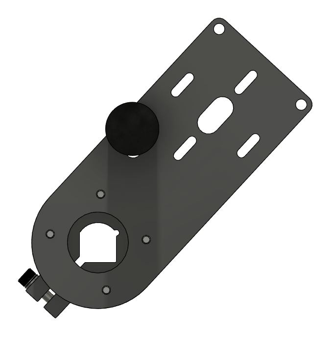
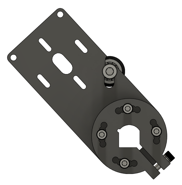
Rev 1
Truth be told, I'm incredibly proud of this. After a few hours in Fusion 360 I have what feels like a no-compromise design. however, before my head stops fitting through the door, I need to do some physical testing and receive feedback from the ESK8 community to validate it. As with any product, I'm sure there will be plenty of revisions to come.
I will not provide a detailed explanation of every design choice, dimension and fastener length, however here are some of the main considerations.
Firstly, you may notice that the clamping mechanism is not a direct copy of the Boardnamics motor mount. This is to reduce the number of parts, therefore theoretically reducing the number of things that can go wrong and hopefully providing a more stable solution. My only concern with this is that the displacement of the adjustable holes when the clamp is tightened may prevent the screws from aligning with the holes in the "arm".
This brings me onto my next point, which is that the motor position is adjustable unlike the Boardnamics mount. It is worth noting that the idler will only fit if the motor is in the outermost position from the trucks. I can modify this by increasing the arm length, however I intend to keep this design as compact as possible to prevent the mount from contacting the ground or underside of the deck.
Throughout the design I have intended to minimise the number of manufacturing operations. I have opted to produce this via waterjet cutting, with no milling required whatsoever. This should allow the design to be manufactured at a lower cost than the Boardnamics one, as the channel around the screws which join the clamp to the arm has been redacted.
Originally, I had the idler slot perpendicular to the length of the motor mounting arm. However, I found that by angling it like the Boardnamics one, it allowed me to reduce the arm length without the idler interfering with the motor or wheel. It is fascinating how you only come to understand seemingly meaningless design decisions when you explore the product from the ground up yourself. Or maybe I'm just tipsy.
-
Motor Mount
09/14/2022 at 04:17 • 0 commentsDIY or Buy?
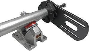
My research (window shopping) has shown me that high quality motor mounts, the ones which are not likely to vibrate off mid-journey, are either ridiculously expensive or sold out. What separates a high quality mount from a low quality one in my eyes is a mounting profile specific for the brand of trucks used.
For example, the image above depicts the most common, low cost design sold by Chinese manufacturers. It features a round profile with grub screws used to clamp down on the truck. This is not a robust mechanism by any means, as the grub screws provide very little contact with the hanger, can be loosened easily by vibration, and if the grub screws are worn down, there is no means of constraining the motor mount to the hanger in the lateral plane.
As a degree apprentice, luckily I have access (provided I sweet talk the technicians...) to my Uni's CNC machinery including a waterjet cutter. Theoretically this should allow me to design my ideal motor mount for a low cost. Time to design!
Specification
The motor mount must fulfil the following criteria:
- Fits Caliber profile trucks
- Fits Flipsky 6354 motor
- Is no wider than 9mm at the motor end
Some optional features I'd also like to include are:
- Angle adjustment to fine-tune the position of the motor
- Belt tension adjustment
- Idlers to improve torque transmission
- Crossbars for improved strength and style
Inspiration
"There is no such thing as an original idea. Only improved versions of their predecessors"
(Paraphrased from a source I cannot remember)
Essentially, my plan here is not to start from scratch, but to draw inspiration from (i.e. strategic copying) existing designs born from the ESK8 community.
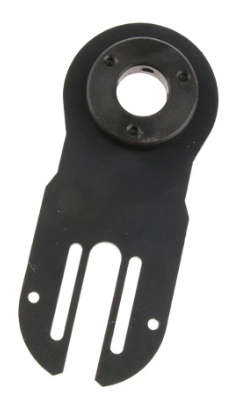
1) DIYE
![]()
Pros:
- Adjustable tension via motor position
- Adjustable clamping force via C-shaped truck mount
- Specific to caliber profile
- Low cost to produce - can mostly be laser cut, with minimal machining required
Cons:
- Angle not adjustable
- Too thin at motor end?
- No idler support
- No crossbar support
2) Eskating Europe
![Electric skateboard motor mount by Eskating Europe]()
Pros:
- Adjustable clamping force via C-shaped truck mount
- Strain relief in clamp profile
- Nyloc nuts for vibration resistance
- Specific to caliber profile
- Low cost to produce - can mostly be laser cut, with minimal machining required
Cons:
- Angle not adjustable
- Tension not adjustable
- No idler support
- No crossbar support
3) MBoards
![Premium Motor Mount]()
Pros:
- Adjustable clamping force via 2-part clamp, with additional grub screws
- Adjustable tension via motor position
- Specific to caliber profile
- Nyloc nuts for vibration resistance
- Low cost to produce - can mostly be laser cut, with minimal machining required
Cons:
- Angle not adjustable
- No idler support
- No crossbar support
4) Nexusboards
![Caliber Street Electric Skateboard Motor Mount – Nexus Boards]()
Pros:
- Swappable clamping core, specific to caliber profile, with strain relief on both the core and the core clamp
- Adjustable tension via motor position and idler
- Idler support
- Adjustable angle
Cons:
- Complicated design - no need for swappable core if buying for specific trucks
- Not a clue what that metal plate at the motor end is for
- Lots of expensive machining processes
5) Boardnamics
![Boardnamics New Caliber II Motor Mounts - New Items For Sale - Electric Skateboard Builders Forum | Learn How to Build your own E-board]() Pros:
Pros:- Adjustable clamping force via 2-part clamp
- Nyloc nuts for vibration resistance
- Low cost to produce - can mostly be laser cut, with minimal machining required
- Adjustable tension
- Adjustable angle
- Crossbar support
Cons:
- No idler support
6) Boardnamics (with Idler)
![Caliber II Motor Mount with Idler Tensioner | Boardnamics]()
Pros:
- Adjustable clamping force via 2-part clamp
- Nyloc nuts for vibration resistance
- Low cost to produce - can mostly be laser cut, with minimal machining required
- Adjustable tension (via idler)
- Adjustable angle
- Crossbar support
Cons:
- Too good to be true?
7) Alien Drive Systems
![Alien Drive System | New: Universal Bolt-on Motor Mount Design - ESK8 Parts Market - Electric Skateboard Builders Forum | Learn How to Build your own E-board]()
Pros:
- Swappable clamping core, specific to caliber profile with strain relief in core
- Adjustable tension via motor position
- Adjustable angle
Cons:
- No idler support
- No crossbar support
- Lots of expensive machining processes
Conclusion
I'm sure there are a whole host of other designs out there that I haven't researched deep enough to find, however this should cover a good 80% of the different species of caliber motor mount on the market.
It is clear that the Boarnamics motor mount with idler meets all the success criteria, so the next step is to replicate the design for my own build.
-
CAD
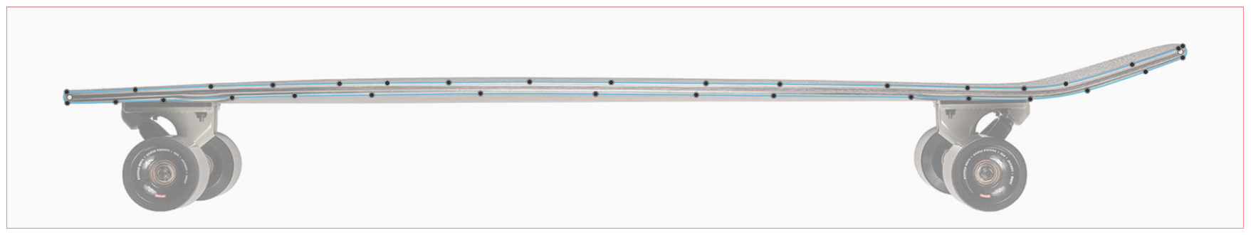
09/14/2022 at 04:08 • 0 commentsDeck
Whilst I was waiting for my new Caliber trucks to arrive, I wanted to produce a CAD model of the board to help visualise the overall assembly.
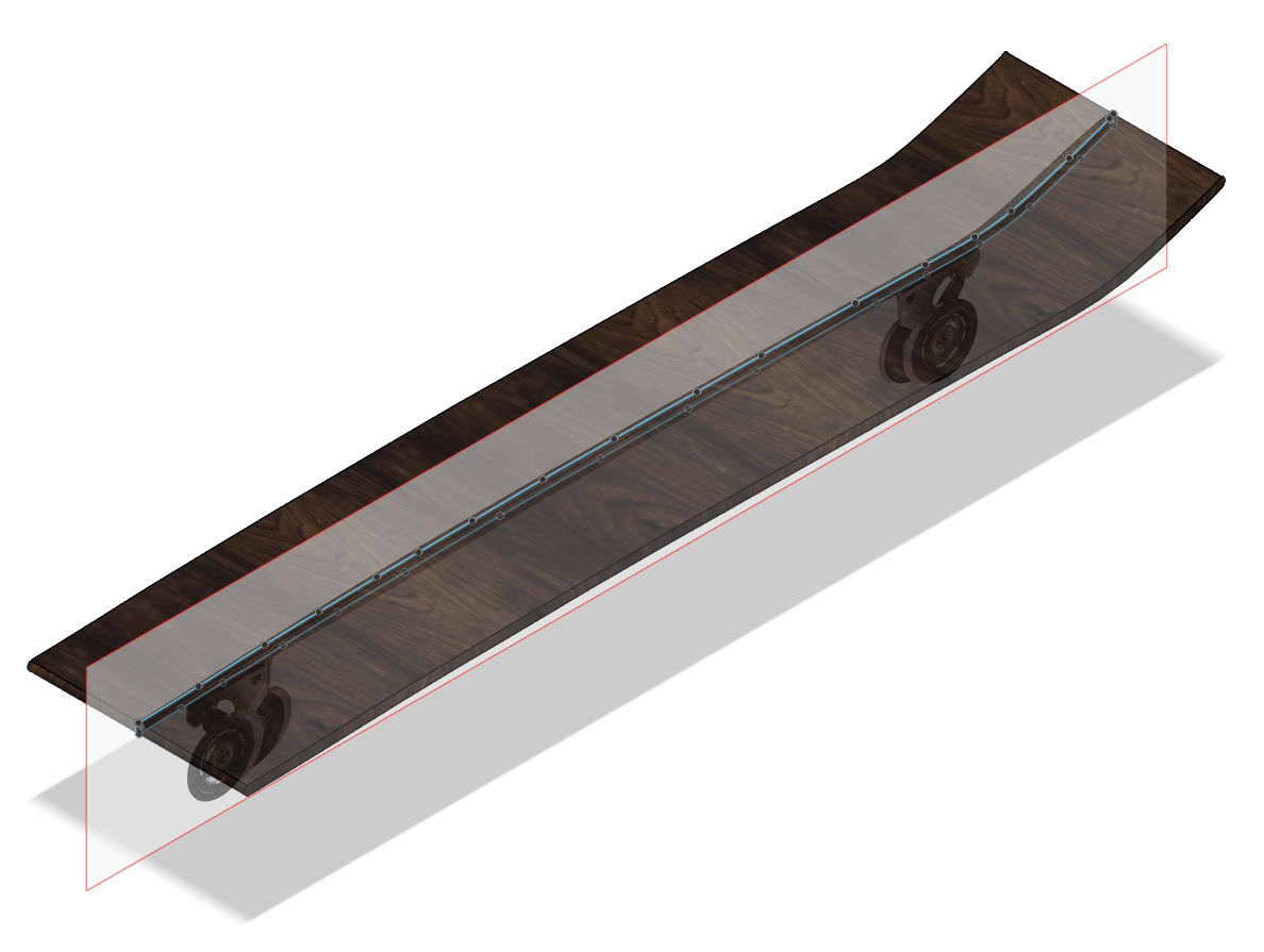
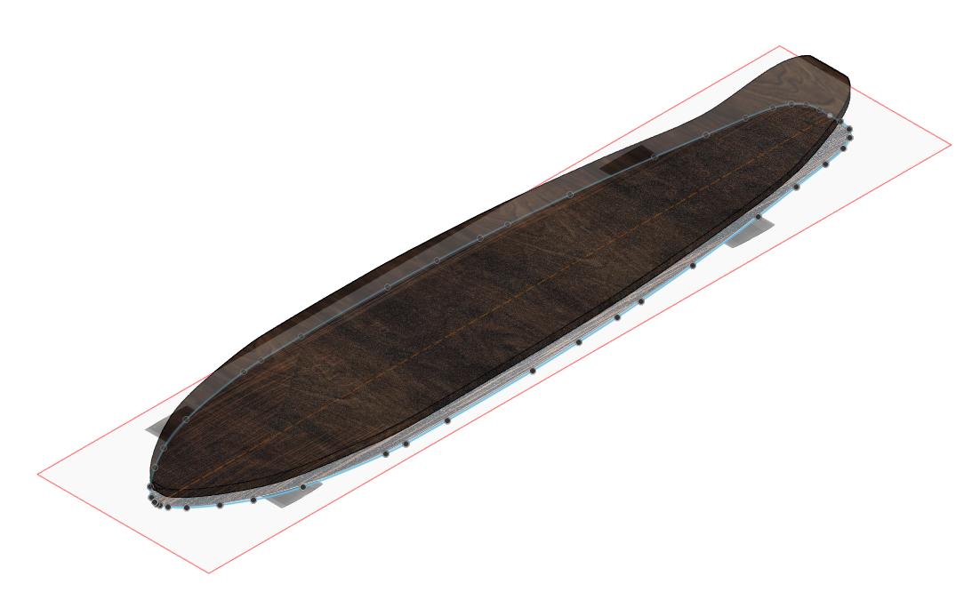
I began by importing the pictures of the deck from here into Fusion 360. This gave me a basis to sketch from:
I then extruded the base sketch to produce a blank of the board, that I cut to shape by intersecting the top-view:
I then added holes and chamfers as appropriate. It's worth noting that the holes are not perfect - the tops/bottoms are not flat as I used splines to model the deck. This makes them difficult to assemble components to accurately. I could have gone to the hassle of getting it perfect which would allow me to design parts like the electronics enclosure more accurately in CAD.
However I think there's something satisfying about getting more hands-on from time to time. As a mechanical engineer, and someone who spends more time modifying their 3D printers than they do actually using them, I tend to turn into a bit of a CAD monkey sometimes. This can lead to mistakes which may easily be avoided by simply measuring things in real life, or producing cardboard templates and taking some hand tools into the equation, because in the real world dimensions are not perfect and tolerances come into play.
Anyway, the deck is now modelled up. Like I said, this CAD model will serve more as a visual aid for the proportions of the board and component placement than it will as a detailed design record.
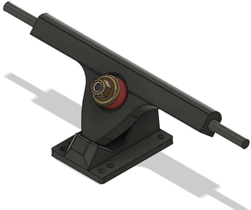
Trucks
I will hold my hands up and admit I cheated a little here. I found this model on GrabCAD for 50 degree Caliber trucks. These are slightly different to the ones I will be using, which use a 44 degree baseplate and raked hanger, but the model will suffice.
I extended the hanger width to 184mm, painted all the parts in pretty colours, and assembled them with the correct constraints.
Wheels
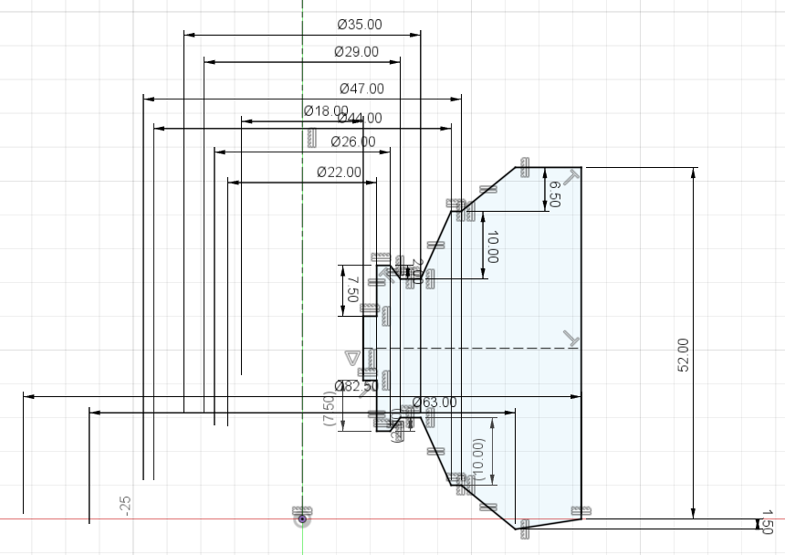
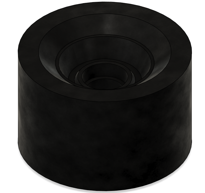
These were tougher to model. I started with a revolve which included all of the small chamfers and main surfaces:
In hindisght this makes it harder to manage the relationships between different constraints, and modify dimensions without moving other aspects of the sketch. But, it worked I guess.
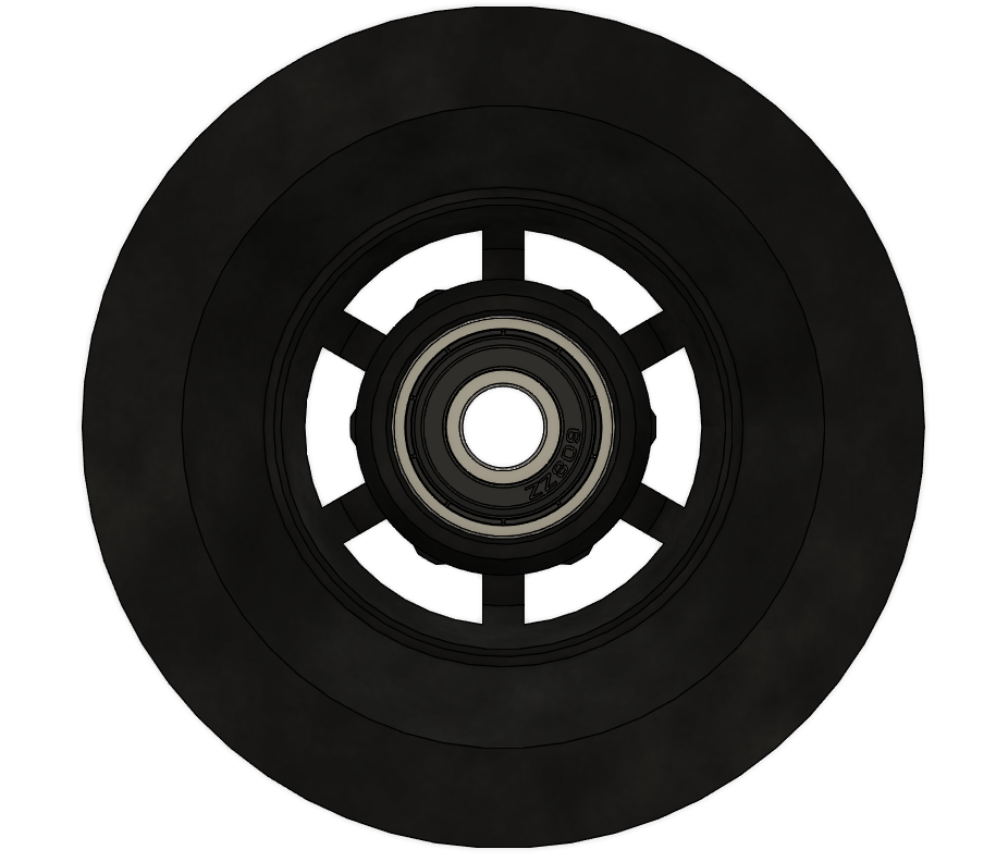
I added a few extra dress-up features where needed, and then drew the cut out for the ABEC-style mounting holes. This was then extruded through, and patterned around the centre.
Lastly, I assembled in some standard 608 bearings found on GrabCAD.
Draft Assembly
With all of the components of the basic deck ready to go, I chucked all the models into a soup, threw in some herbs and spices and nuts and bolts, and out came this:
![]()
At least now this project has a nice cover photo to use!
-
Mechanical Components
08/20/2022 at 13:00 • 2 commentsThe drivetrain (at least, by my definition) includes the mechanical components which move the skateboard forwards. This is the most important part of the build, and will drive the requirements for the electronics. The drivetrain consists of the following:
- Motor(s)
- Pulley(s)
- Belt(s)
These components structurally and functionally support, or are supported by the following:
- Trucks
- Motor mount(s)
- Wheels
Before exploring my options for each of these, I want to make it clear that I am hoping to reuse as much of the original setup as possible, only swapping out components which would require irreversible modifications. This is for a few reasons: firstly, to preserve the overall look and feel of the board. Secondly, to keep cost down; and thirdly to add some challenge to the build. intuitively this means hopefully reusing the trucks, but not the wheels as they would need modifying. Also, this means I will be using a belt-drive rather than hub motors or direct-drive motors.
Wheels
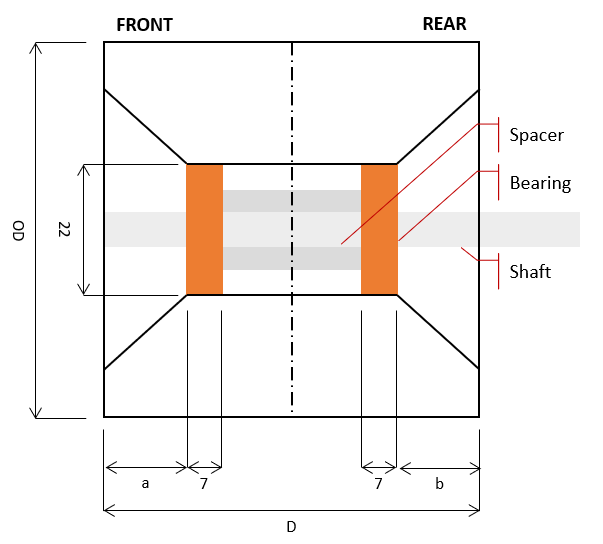
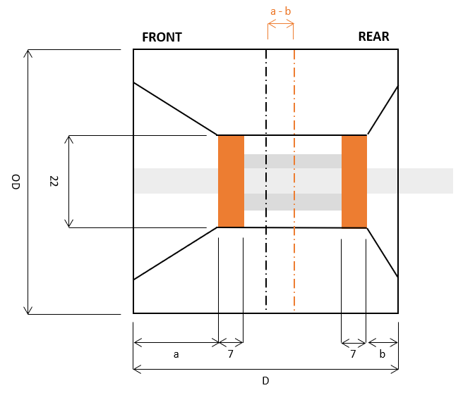
ESK8 wheels come in a range of shapes and sizes, depending on the use case. They can even resemble tiny bike wheels for mountainboarding! This guide is, as far as I can tell, fully comprehensive and incredibly useful. As I will only be powering one side of the board, I'd like the driven to resemble the existing ones as closely as possible. The current wheels can be defined as follows:
It is important to note however, that a and b are not always the same. Offset wheels (such as my existing ones) and side-set wheels (bearing flush with surface) change the weight distribution across the wheel such that the lateral centreline through the bearings is not coincident with that of the wheel.
OD (mm) 70 D (mm) 51 Hardness 83a Shape Conical a - b (mm) 5mm I have toyed with the idea of casting my own hard-cored polyurethane wheels with a 3D printed mould. However, my humble Ender 6 is currently a Frankenstein's monster of r/redneckengineering material due to half-assedly modifying and developing it over the course of the last year. As it currently stands, I don't trust it to produce consistent prints, let alone with more engineering-grade materials which will be safety critical and under significant load. I don't want to have my wheel cores shatter at 20mph downhill! In future I may carry out a project to rectify this.
The closest wheels I can find to these which are commonly available and relatively affordable are the Orangatang Kegel 83a wheels. these have the same hardness and are only 5mm larger in diameter.
![Orangatang Kegel - 83a 80mm – Zenit Longboard]() Unfortunately they only come in this unnecessarily garish lime green and purple combo which doesn't fit the aesthetic of my board. Therefore I need to look for an alternative.
Unfortunately they only come in this unnecessarily garish lime green and purple combo which doesn't fit the aesthetic of my board. Therefore I need to look for an alternative. I briefly explored various buy & sell groups, and a selection of different UK/EU ESK8 vendors but struggled to find components. As the ESK8 market is still in infancy, especially outside of the US it seems, most sellers and vendors offer full setups or conversion kits as these appeal to a larger audience. I caved in, and decided to visit AliExpress, where I came across these:
Though not particularly exciting, these wheels match my requirements almost perfectly. They are black, only 8 mm larger in diameter than the stock globe wheels, have a hardness of 80A and have an ABEC style core. They are also very cheap, at only £6.81 per wheel at the time of writing this. I am aware that by limiting the outer diameter of the wheel, which is relatively small in terms of ESK8 wheels, I am trading stability and "momentum" for nimble handling and acceleration - this is driven by the focus on aesthetics. Whether this comes back to bite me or not in future we shall see! I hold some concerns about the quality of the wheel also, as this is an unknown vendor. However, given that I am not planning to use the setup in harsh environments or offroad, these should suffice.
For bearings, I will use the tried and tested Bones Red's that are the standard for almost any skateboard.
Mechanical Architecture
The best place to start would probably be by identifying some requirements. However, figuring out what spec motor to use and building around that seemed more fun so we'll go that route. When I started thinking about the motors, here are some of the questions which came to mind.
- How many motors do I need?
- FWD, RWD or AWD?
- What effect does the voltage have on the overall performance?
- What effect does the current draw have on the overall performance?
- Should I opt for sensored or sensorless motors?
Let's start by figuring out how many motors we need. Most belt-driven ESK8 boards appear to use only one or two motors. Cost is a large driver here - with more motors I will need a larger battery, more ESC's and it will become very expensive very quickly so I will rule out 4WD.
I found this video which provides a good comparison. This thread also has some good information.
Assuming the same battery capacity, 2WD provides more torque than 1WD but not more speed as the two are running in parallel. With a 2WD setup the setup is also balanced in terms of the weight and forward force. This doesn't necessarily matter at lower speeds - with 1WD, a user with skateboarding experience or good balance can counterbalance any drift towards one side but this may prove to be an annoyance. At higher speeds however, this drift would become more pronounced and lead to "speed wobbles".
1WD is technically more efficient than 2WD due to natural inefficiencies in the power delivery route being doubled. This is not significant enough to make a decision on, as I will design the battery to have more capacity than necessary to build in redundancy.
2WD also provides redundancy. If one motor fails, the other can pick up the slack, albeit at a lower speed. The same goes for braking too - if one pulley snaps under hard braking, the other motor can provide braking capacity. For me this is important - I wouldn't want to get halfway through my commute and have to carry a heavy board home, which I would probably have to do as belt-driven setups are known to have significant rolling resistance.
I will settle on 2WD for the above reasons, and also because it provides more scope for upgrading the battery and wheels in future if necessary.
Now I must decide whether to use FWD or RWD.
With motors at the front, you lose traction going uphill as your weight is distributed further back. On the flip side, FWD allows you to go much faster downhill for the opposite reasons. As I plan to use this board for transport rather than speed I would rather the traction (especially with small PU wheels) so RWD is preferred.
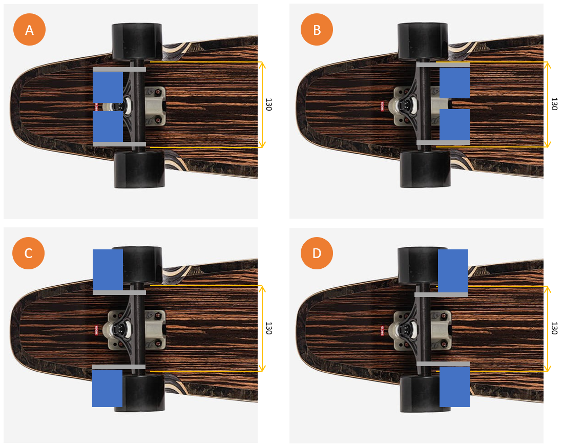
Now I need to decide what configuration the motors will be in.
A and C face the opposite direction to the centre of the board where the electronics will be. This will make cable routing more difficult. Although the range of movement for the trucks would be greater in these configurations, as they will not touch the board during turning, they also expose the motors more and increase the risk of them being damaged. Therefore they can be ruled out.
Option D allows for larger motors, but limits what size wheels can be used. It also exposes the motors, and increases the risk of damage. Therefore, although the motor dimensions will be limited, I will proceed with option B.
After writing this, I realised that options C and D would be invalid regardless, as the pulley would not reach the wheels...
The wheel offset and motor mount position will drive the available motor space. However, as there is no information about the wheel offset within the product description, I have bought the wheels so I can take measurements myself.
2 days after finding them on Amazon, I assembled them, only to discover the rear offset is even larger.
This is a problem because the motor mount, which I estimate will be about 5mm thick, and belt drive, which I estimate will be about 20-25mm thick including the motor shaft, leaves me with enough room for only 1 motor:
From here, I begun to overcomplicate things:
- Could I cut the wheel laterally to reduce the offset, such that it resembles something closer to a side-set wheel?
- This would reduce the contact area and therefore reduce traction, in a setup already unsuited for ESK8 scale speeds due to the narrow wheelbase.
- Could I design a custom motor mount and pulley system - first prototyping with a 3D printer before committing to machined parts?
- This would be significantly more expensive than just buying ESK8-style trucks and the reliability of the system can not be vouched for without extensive testing.
I tried explaining this whole predicament to my girlfriend, who then proceeded to metaphorically slap me back to reality with how much I am overcomplicating this and how unsafe it could be. My priority is keeping costs down. Hers is making sure I get back from work in one piece.
Much of the lessons learned even up to this point could have been quickly figured out by simply following the advice of the online forums and videos, and trusting the collective knowledge and experiences. However, I have always believed it is much more fun to work these things out for yourself (hence why I'm a mechanical engineer I guess!) and helps you develop a better understanding of the design choices other people have made.
On the plus side, this gives me much more design freedom with less constraints to work around. Let's delve deeper into the motors as this will drive the size of our trucks.
Motors
The best place to start would probably be by identifying some requirements. - Jamie 2022
Let's follow that advice so I don't end up rushing into things again. Here are the main things (in no particular order) to consider:
- Dimensions
- This is exactly what it says on the tin. Electric skateboard motors follow a consistent naming convention to define the external diameter and length.
- For example, a 6368 motor has a 63mm diameter, and is 68mm long.
- Larger diameter motors may reduce the range of motion: on the side where the board leans towards the ground, the motor may contact the underside of the board, preventing the user from turning.
- The length of the motor drives the choice of trucks.
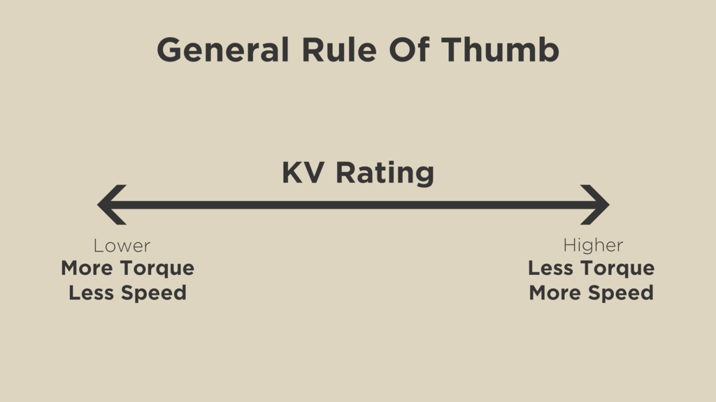
- Kv rating
- Kv (RPM per Volt) is not to be confused with KV (kilovolt).
- For motors of approximately the same shape and size, the rule of thumb is that lower Kv equates to higher torque and lower max speed, in contrast to high Kv which equates to lower torque and higher max speed.
- ESK8 motors will generally range from 140Kv to 220Kv. This video by MBoards states that the "sweet spot" is between 180-200Kv for a good balance of torque and speed.
![How to Choose a Motor – MBoards]() Maximum current draw
Maximum current draw- Beefy motors are more power hungry and will require higher current-rated components to avoid causing damage to the electronics. This may be avoided by using a current-limiting VESC but this is a topic I will delve more into later.
- Typically this value will range from 50 - 100A.
- Running the motors at high speeds or up steep inclines for an extended period of time will draw lots of current, and therefore drain the battery very quickly. It will also make everything much hotter which could damage other electrical components.
- Maximum voltage input
- This linearly relates to the maximum speed of the motor.
- Imagine you have a 200Kv motor running at 10S (36V). It is attached to 70mm wheels via a 2:1 pulley reduction. Assuming the system is 80% efficient, this gives you a top speed of approximately 24mph.
- The same setup, running at half the input voltage, 5S (18V) has a top speed of approximately 12mph
- You can use this calculator to estimate your top speed as I have done.
![The Music Telegraph] Ohm`s Law]()
- Sensored or sensorless
- Sensored motors use hall effect sensors within the motor housing to determine the internal rotor position, which is fed back to the ESC and allows a "smooth start" from standstill. This is particularly useful for boards where the user is strapped in (i.e. mountainboarding).
- Sensored motors provide extra data and customizability to the setup, at the cost of increasing complexity, reliability and price.
- Sensors will add potential failure points to the system. For example, if the sensor comes loose or is damaged during riding, it may prevent the motor from working. If this occurs suddenly it could be dangerous to the rider.
- Sensorless motors are just like me - simple. They take a power input, and spin. No fancy data, no added complexity. They are cheaper and more reliable.
- However, sensorless motors may not be suitable for more casual riders who have no prior skateboarding experience, or struggle with their balance and want to start from standstill.
- With sensorless motors it is advised to push-off to get them moving, otherwise they may get damaged, or provide a sudden change in momentum which leaves the rider writhing in agony on the pavement.
Cost is one of the largest drivers of this project, therefore my decision on which motors to use will ultimately boil down to the price/performance ratio. However, as my board will mostly be used for cruising on smooth, paved surfaces without too many hills, I know to look at the less expensive end of the market.
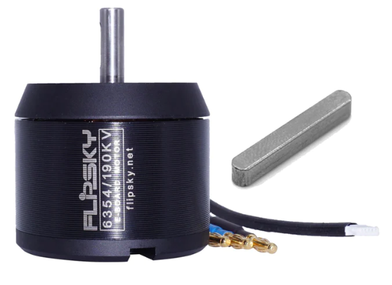
Having compared a few different options, I decided on this absolute beast of a device:
The Flipsky 6354 BLDC motor has the following specs:
Specification Value Diameter 63mm Length 54mm Kv Rating 190Kv Maximum Current Draw 65A Maximum Voltage Input 12S ( ~ 43V) Sensors Hall Effect ![6354 motor]() Not only does this motor pack an absolute punch for its size and price, but it is also "battle hardened" which is marketing speak for enclosed, to prevent debris from damaging it during operation, and can run in sensorless mode.
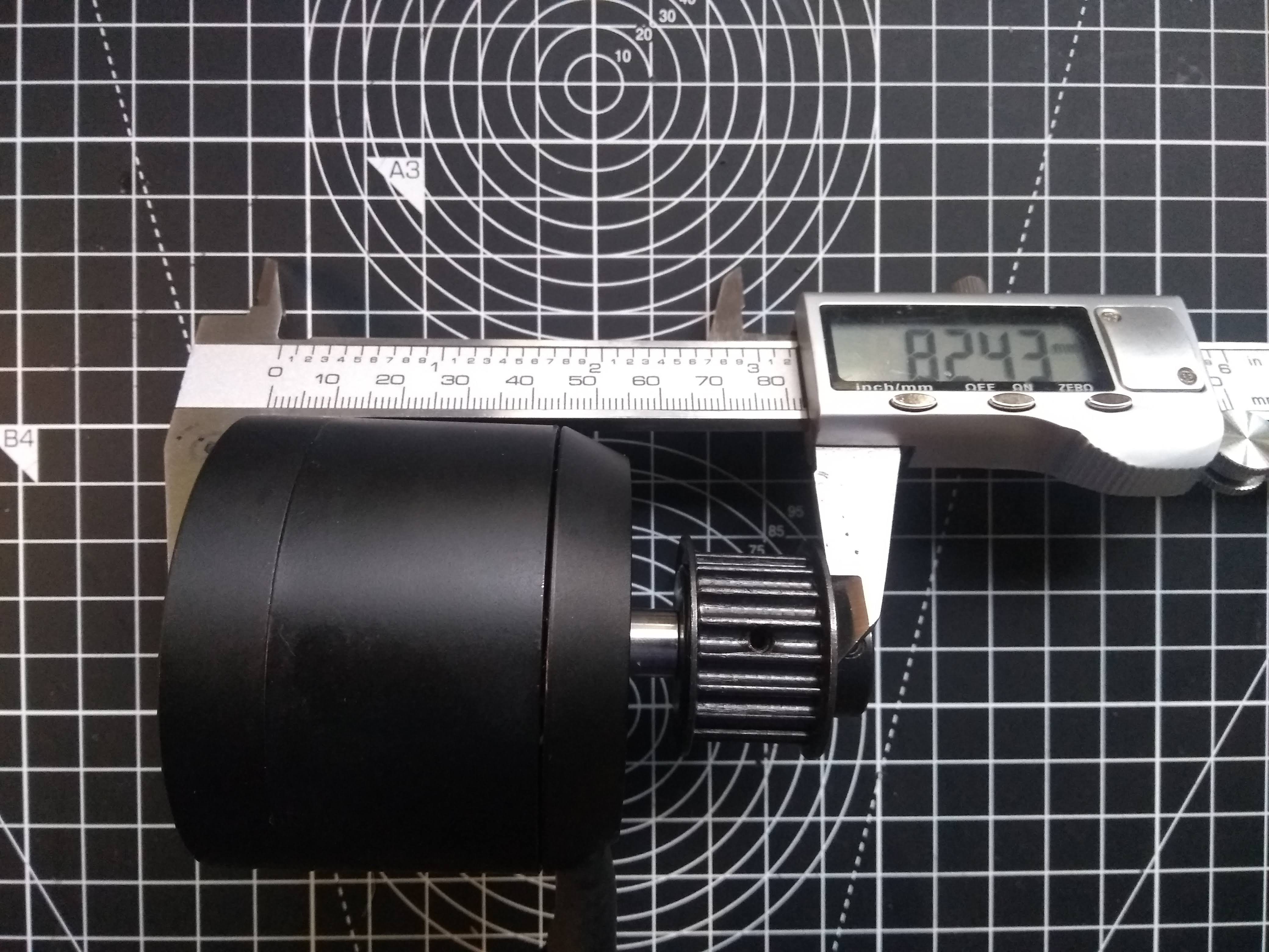
Not only does this motor pack an absolute punch for its size and price, but it is also "battle hardened" which is marketing speak for enclosed, to prevent debris from damaging it during operation, and can run in sensorless mode. I was slightly trigger-happy and accidentally ordered the default 15mm belt, 16T pulley with it. I see this as a positive as it is probably cheaper than buying a pulley separately, and means I have less decisions to make.
![]()
On a side-note, I had actually written a much more comprehensive guide for this section, including an in-depth justification of my motor choice. But, in clearing my browser cookies I also cleared 2 hours of progress in this log... Besides, if you're looking to build an electric skateboard of your own, you can gather more accurate and concise information by scouring more experienced ESK8 forums and guides than from here.
Trucks
With the current motor and pulley combo, the hanger width will need to be approximately 210mm or more.
I decided to visit some ESK8 forums to see what trucks other people have used with a dual Flipsky 6354 setup. As with most electric skateboard builds, the Caliber II's seem to be the most common trucks. This is for a few reasons:
- They have a squared-off hanger profile, which makes them ideal for mounting motors to.
- They are reverse kingpin trucks, which makes them stable at higher speeds.
- They are relatively inexpensive.
So, I went online to buy some Caliber trucks. Thankfully, they are not difficult to find and there is a huge variety of different colours and configurations. However, I couldn't seem to find any with a hanger width greater than 184mm. As my wheels have a 15mm offset, it would be impossible to use these.
How on earth are people building their electric skateboards with dual 6354 motors and Caliber II's if the hanger isn't wide enough?
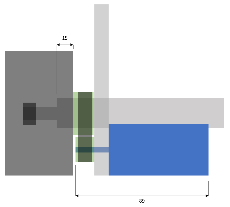
Firstly I flipped the pulley. This saves 7mm:
![]()
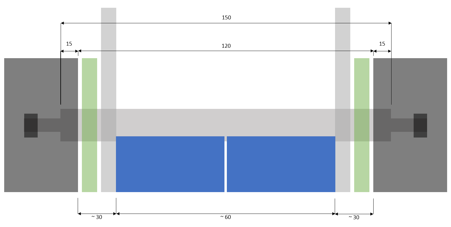
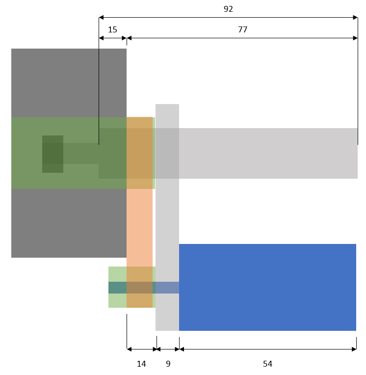
I then created a diagram to build a better understanding of how everything will be assembled:
It is clear now that with the Caliber II's, I would have about 14mm (give or take 1mm, my measurements were rough) for the belt. Although this means I cannot use 15mm wide belts as the pulley is designed to, I should be able to get away with 12mm belts or similar widths.
So now it has been validated that the hanger width is sufficient, I need to decide which variant of the trucks I will use. For this, I need to understand a few things about longboard trucks.
From raked vs unraked hangers, to 44° vs 50° baseplates, to ball vs cylindrical pivot points, and more: there is a huge range of parameters to decide between. This guide does a fantastic at explaining them all.
I am going to go with the Caliber III 184mm 44° raked variant in this earthy "Bourbon" colour that matches the rest of the board. I have chosen a 44° over 50° baseplate as it makes the board less responsive to leaning, which makes it more stable at high speeds. If I want to experiment further with the angle I can always buy wedged riser pads.
I am going for raked trucks, rather than unraked trucks, as I can experiment with positive or negative rake. Rake is a difficult concept to grasp, but essentially, negative rake provides a more linear turn, which makes it predictable and less "carvy". It also lowers the ride height, which could potentially cause the motors to touch the board prematurely and prevent tighter turns, but this can be solved with riser pads. Positive rake provides a "diving" feel as you lean into a turn, making the board more manoeuvrable.
-
Start of the Journey
08/20/2022 at 12:36 • 0 commentsBackstory
It's August 2022 near London...
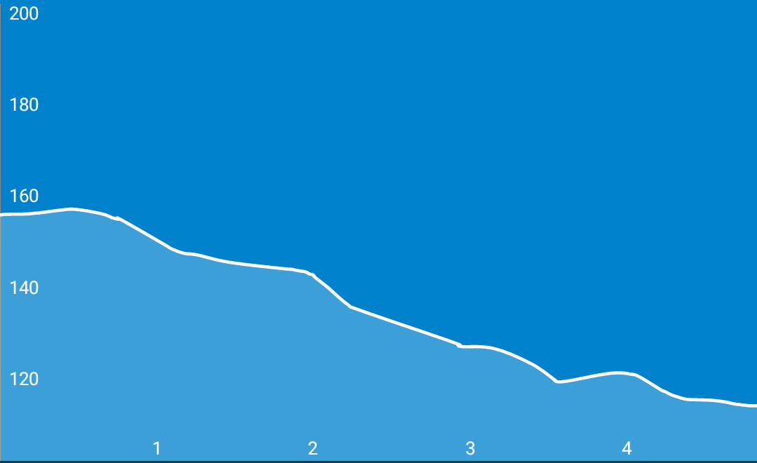
The sun beats down on your face, whilst you painstakingly push a 3.7kg slab of wood up 45m of elevation, with only 3m of downhill, over 4.8km.
![]()
The gradient varies by 0-3% throughout the journey. Although this is mostly flat, you're on your way back from work, exhausted and drained with a 4.5kg backpack. You weigh approximately 70kg. It only takes you 15 minutes on the way into work, but the way back is almost half an hour!
Sweat rolls down your cheeks, drenches your back, and floods your nethers in the 32°C heat. You think to yourself - "if only this longboard was electric! That way, I could still enjoy skating to work, without dreading the journey home."
As you may have already guessed, this person is me. As a skateboarder, I have previously had an elitist mindset against longboards. God forbid electric ones, how could you let such a heinous display of consumerised technology take the spotlight of a classically skillful and dangerous sport?
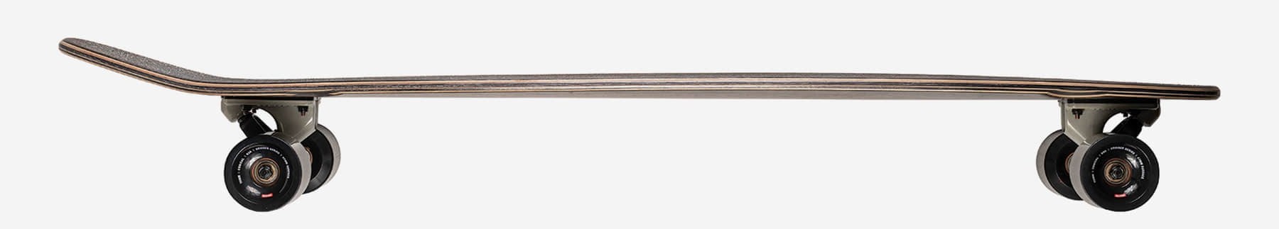
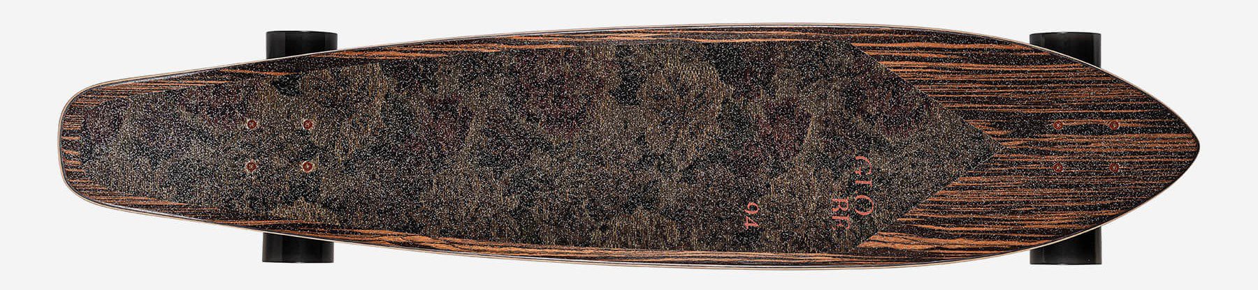
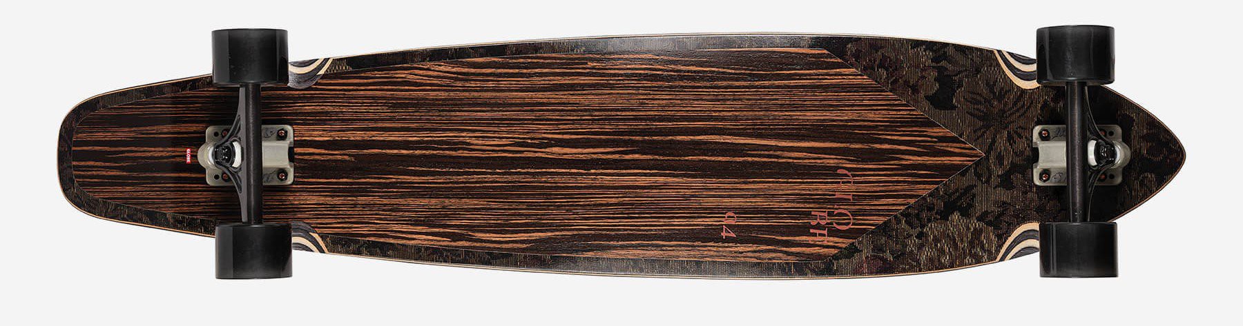
However, since owning my (now beloved) Globe Byron Bay 43" setup in Ebony/Nightshade, after being shown the joys of downhill longboarding (yes I'm aware this is not a downhill setup!) my mindset has changed.
![]()
![]()
![]()
This Surf-inspired squash tail longboard has a Mellow concave, with kicktail made of Ebony wood + Resin-8 hard rock maple. It features 150mm Slant reverse kingpin trucks and 70mm 83a wheels. I would do unspeakable things to this beauty.
Research & Specification
I performed some basic research into electric longboards to develop a basic understanding of what components I will need. This involved binging builds on YouTube instead of working from home, scouring ESK8 forums and scrolling through Reddit.
From this, I can break this project down into a few major categories:
- Drivetrain
- Battery & BMS
- ESC
- Transmitter & Receiver
- Enclosure
- Additional Features (LEDs, speakers, regenerative braking, etc)
The following project logs will delve deeper into each.
Nagini: A DIY Electric Longboard
Designing and building a custom electric longboard for commuting.


 Pros:
Pros:

 Lastly, I assembled in some standard 608 bearings found on GrabCAD.
 Unfortunately they only come in this unnecessarily garish lime green and purple combo which doesn't fit the aesthetic of my board. Therefore I need to look for an alternative.
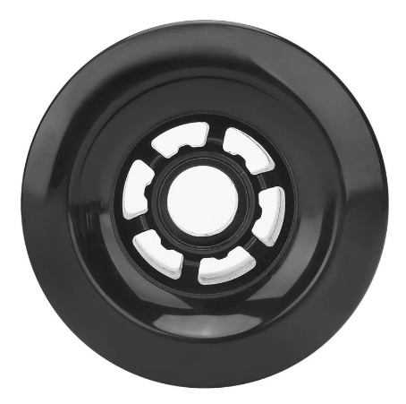
 Maximum current draw
![The Music Telegraph] Ohm`s Law](http://www.themusictelegraph.com/imgdata/themusictelegraph_com/201901/2019012940453364.png)
 The Flipsky 6354 BLDC motor has the following specs:
 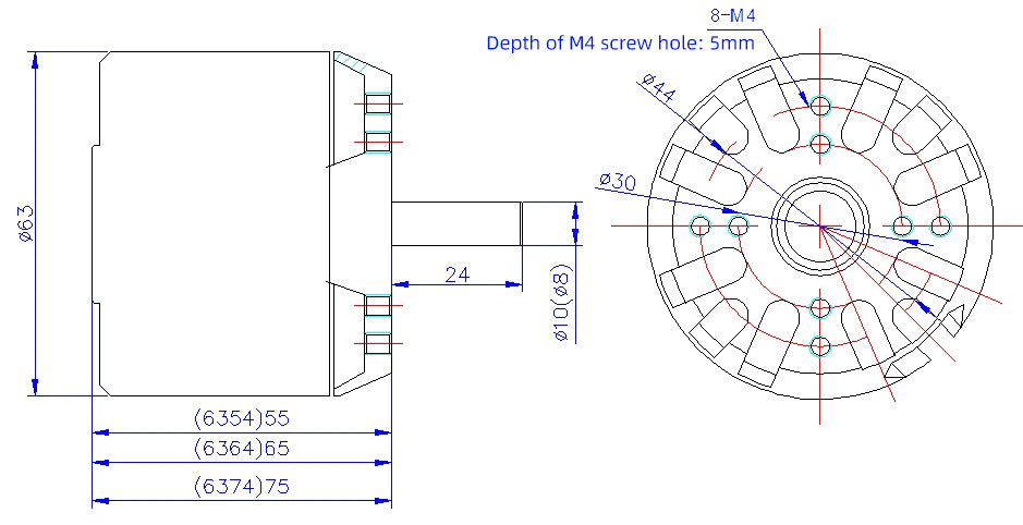 Not only does this motor pack an absolute punch for its size and price, but it is also "battle hardened" which is marketing speak for enclosed, to prevent debris from damaging it during operation, and can run in sensorless mode.
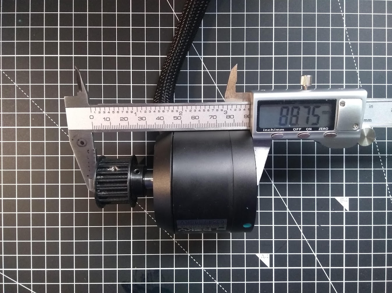
 It is clear now that with the Caliber II's, I would have about 14mm (give or take 1mm, my measurements were rough) for the belt. Although this means I cannot use 15mm wide belts as the pulley is designed to, I should be able to get away with 12mm belts or similar widths.
 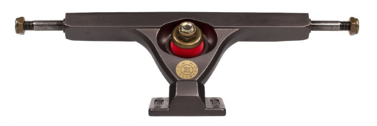 I am going to go with the Caliber III 184mm 44° raked variant in this earthy "Bourbon" colour that matches the rest of the board. I have chosen a 44° over 50° baseplate as it makes the board less responsive to leaning, which makes it more stable at high speeds. If I want to experiment further with the angle I can always buy wedged riser pads.