Some of these steps have not yet been implemented into the prototype glider such as the PCB and circuit rack print. If you attempt this build be prepared to make modifications as you go since this is not a completed design as of yet.
2
Control Boards
Begin by printing the BackEndCircuitRack, and the Circuit_rack_encap_mount. We attempted to print these parts however the print failed part way through, for a more reliable method the stl file should be separated into two separate halves to print that can be glued together. Better yet would be to use the BlueROV pre-built circuit rack.
Once the parts are printed insert the Arduino Mega and Raspberry Pi into the BackEndCircuitRack. There are mounting holes in the print for them.
The circuit rack and all remaining 3D parts can be joined with wood or metal square stock in the provided rectangular holes. This design was from the OSUG project and was included to add some rigidity to the parts for when any of the actuators are running.
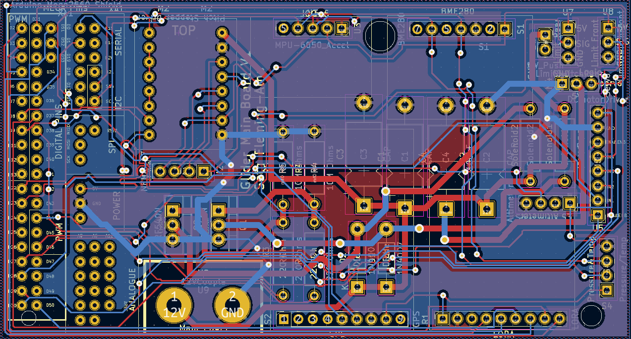
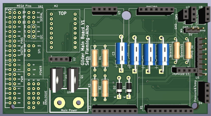
Have the PCB provided printed and solder on all of the parts as labelled on the PCB.
Connect the PCB to the Arduino Mega as labelled on the PCB.
Connect the Arduino Mega to the raspberry pi through a short USB cable and connect the pi to the portable power supply. Boot the pi and connect it to your local WiFi network, you should then be able to reprogram the Arduino wirelessly through VNC viewer.
3
Roll Motor
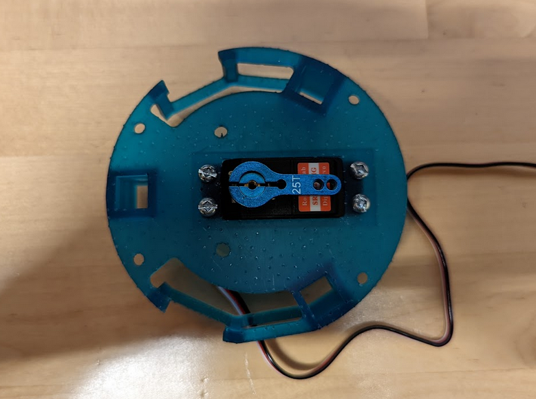
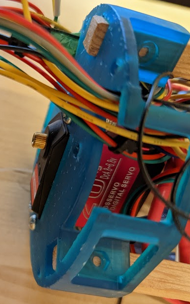
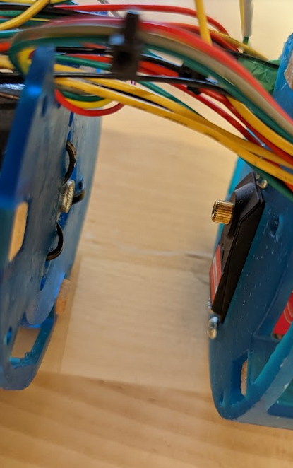
Print the ServoRollMotorMount and attach the servo. This section will then attach to the brain housing. The servo can be plugged directly into the PCB. The ServoRollMotorMount print can be attached with square-stock.
This unit will then connect to the Pitch motor housing.
Print the Pitch_motor_backplate and attach the servo gear connection into the inner circle, for our prototype it was glued and zip tied in.
These two parts can then be joined. The gear you see being attached here will be replaced with a similar fitting (https://bc-robotics.com/shop/metal-rc-servo-arm-25t/) that also has a locking collar to keep both parts connected.
4
Pitch Engine
Print 2 Battery_mount_bearings, the Pitch_motor_back_plate and the Pitch_motor_mount. Attach the linear bearing with zip ties to the Battery_mount_bearings and attach battery springs through the holes. Mount limit switches to the rails and insert them into the assembly. Connect the threaded rod to the stepper motor and mount the motor. Attach one of the Battery_mount_bearings to the brass nut threaded for the rod and insert the other end of the rod into a 5th linear bearing.
This is an image of half of the battery pack, simply print an additional Battery_mount_bearings and orientate it to face the others in order to fit all 12 cells.
Insert the 18650 cells into the pack in the following configuration Solder on the BMS according to the KiCad file and insulate the power supply from the surrounding wires. Add friction-less tape as needed. (Again this should be resigned so that there is no contact with the outer wall if possible)
5
Ballast Engine
Print the Ballast Engine Enclosure
Connect the pump, solenoids and bladder. The vacuum pulled on the glider will pull water in, the pump will only be used to pump water out. The Wiring diagram can be found in the KiCAD files. The bladder will be constrained by a PVC pipe. The bladder itself will be fitted with flex sensors which will be used to determine if the bladder is full or empty.
Depending on the print quality some light filing might be required as you can see above the parts were a bit too snug.
6
Bulk-Heads
Ensure all surfaces are cleaned thoroughly. proceed to lubricate and install O-rings.
On the forward bulkhead install two barbed tube connectors, two blanks (to be replaced with sensors at a later date) and the altimeter. On the rear bulkhead connect a vent plug, two on plugs, the pressure and temperature combined plug and the cable perpetrator plug for charging. As seen in the Wiring diagram on of the on plugs will turn on the raspberry pi, the other turns on the 12V for the actuators.Once all of the plugs/penetrator's have been installed the bulkheads can be screwed onto the printed circuit rack and valve holder on either ends of the glider.
7
Vacuum
The glider requires a vacuum in order to operate. Begin by removing the vacuum plug from the rear bulkhead and insert a Blue ROV vacuum plug (https://bluerobotics.com/store/watertight-enclosures/enclosure-tools-supplies/vacuum-plug/). You can then use either their hand pump (or better yet a motorized vacuum pump) to pull a vacuum on the glider, preferable over 15 InHg. The next step needs to happen quickly, remove the vacuum plug and insert the original plug so as to maintain as much of a vacuum as possible.
If you want to measure the vacuum inside the glider, connect to the pi with VNC viewer and proceed to open the Arduino IDE and upload the BME280 test, this script can either be found in examples or in the library of scripts provided. Opening the serial terminal now should give you an output of the temperature, humidity and pressure inside the glider.
8
Boot Sequence
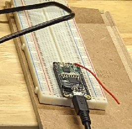
To run the gliders dead reckoning test dives first turn both power plugs to on. If you want to reprogram the Arduino ensure that the 12V actuator power is disabled to avoid accidental damage. Wait for a minute or two for the system to boot and for the glider to run a brief diagnostic. While the glider is booting connect the long range radio to your computer and open the Arduino IDE and load the appropriate board (Feather 32u4) and connect to the serial port being used.
Open the serial monitor in the Arduino IDE and it should say the radio is 'Waiting for command". If the feather requires reprogramming simply upload the feather_command_control script provided.
The glider should be booted now, to run the test dive script send "dive" in the radio's serial terminal. The glider should being by shifting its pitch-weight forward, then its will open the first solenoid valve for the vacuum to pull water in, once it has reached a certain time (the final version will rely on a depth or altimeter measurement) it will pitch the battery back then proceed to open the second valve and pump the water out of the ballast.
If this does not happen open VNC viewer on your laptop and connect to the pi. Open the Arduino IDE on the pi when you've remotely connected and open the serial terminal on the Arduino, it will then tell you what went wrong during its diagnostics.
9
CODE
The first code chunk declares the variables and establishes connections
///////////////////////////////////stepper pitch//////////////////////////////////For both Steppers red,yellow,white,green going away from capacitor///////////////// const int EN_Stepper_Pitch = 22; const int Step_Stepper_Pitch = 8; const int Dir_Stepper_Pitch = 23;
float Roll = 0; int rollSteps = 250;
int DiveAngle = 26; int DiveRangeAdjust = 5;
int depth = 0;
//////////////////////////////////int Ballast; int MAXBALLAST = 800; int TraverseBallast = 1400; long DIVE; int BallastDive = 4000; int BallastRise = 2500; int TIMEOUT = 100;
////////////////////////////tds//////// This sensor is not currently installed but once a suitable fitting is found the code is ready and working #define TdsSensorPin A1 GravityTDS gravityTds; float temperature; float tdsValue = 0;
// Change to 434.0 or other frequency, must match RX's freq! #define RF95_FREQ 915.0
// Singleton instance of the radio driver RH_RF95 rf95(RFM95_CS, RFM95_INT);
/////////////////////////////////LOGGER//////////////////////// #define LOG_INTERVAL 1000 // millis between entries // how many milliseconds before writing the logged data permanently to disk // set it to the LOG_INTERVAL to write each time (safest) // set it to 10*LOG_INTERVAL to write all data every 10 datareads, you could lose up to // the last 10 reads if power is lost but it uses less power and is much faster!
#define SYNC_INTERVAL 10000 // millis between calls to flush() - to write data to the card uint32_t syncTime = 0;
#define ECHO_TO_SERIAL 0 //echo data to serial, 0 turns it off #define WAIT_TO_START 0 //wait for serial input, if set to 1 then must send arduino a char to start logging
//should make some logging leds for testing
RTC_DS1307 RTC;
const int chipSelect = 10;
File logfile; //the logging file
void setup() { This chunk turns on all of the connects and runs a brief diagnostic
while (!rf95.init()) { Serial.println("LoRa radio init failed"); Serial.println("Uncomment '#define SERIAL_DEBUG' in RH_RF95.cpp for detailed debug info"); while (1); } Serial.println("LoRa radio init OK!");
// Defaults after init are 434.0MHz, modulation GFSK_Rb250Fd250, +13dbM if (!rf95.setFrequency(RF95_FREQ)) { Serial.println("setFrequency failed"); while (1); } Serial.print("Set Freq to: "); Serial.println(RF95_FREQ);
// Defaults after init are 434.0MHz, 13dBm, Bw = 125 kHz, Cr = 4/5, Sf = 1238chips/symbol, CRC on
// The default transmitter power is 13dBm, using PA_BOOST. // If you are using RFM95/96/97/98 modules which uses the PA_BOOST transmitter pin, then // you can set transmitter powers from 5 to 23 dBm: rf95.setTxPower(23, false); //}
int16_t packetnum = 0; // packet counter, we increment per xmission
gravityTds.setPin(TdsSensorPin); gravityTds.setAref(5.0); //reference voltage on ADC, default 5.0V on Arduino UNO gravityTds.setAdcRange(1024); //102 for 10bit ADC;4096 for 12bit ADC gravityTds.begin(); //initialization
sensor.setModel(MS5837::MS5837_30BA); sensor.setFluidDensity(1023); // kg/m^3 (freshwater, 1029 for seawater)
sensor.init();
//////////////////////////////////////ping setup/////////////////////////////////// Uncomment this chunk to run without altimeter
/* pingSerial.begin(9600); Serial.println("Blue Robotics ping1d-simple.ino"); while (!ping.initialize()) { Serial.println("\nPing device failed to initialize!"); Serial.println("Are the Ping rx/tx wired correctly?"); Serial.print("Ping rx is the green wire, and should be connected to Arduino pin "); Serial.print(arduinoTxPin); Serial.println(" (Arduino tx)"); Serial.print("Ping tx is the white wire, and should be connected to Arduino pin "); Serial.print(arduinoRxPin); Serial.println(" (Arduino rx)"); //delay(2000); } */
// initialize the SD card Serial.print("Initializing SD card..."); // make sure that the default chip select pin is set to // output, even if you don't use it: pinMode(10, OUTPUT);
// see if the card is present and can be initialized: if (!SD.begin(chipSelect)) { error("Card failed, or not present"); } Serial.println("card initialized.");
// create a new file char filename[] = "LOGGER00.CSV"; for (uint8_t i = 0; i < 100; i++) { filename[6] = i / 10 + '0'; filename[7] = i % 10 + '0'; if (! SD.exists(filename)) { // only open a new file if it doesn't exist logfile = SD.open(filename, FILE_WRITE); break; // leave the loop! } }
if (! logfile) { error("couldnt create file"); }
Serial.print("Logging to: "); Serial.println(filename);
// connect to RTC Wire.begin(); if (!RTC.begin()) { logfile.println("RTC failed"); #if ECHO_TO_SERIAL Serial.println("RTC failed"); #endif //ECHO_TO_SERIAL }
for (int x = 0; x < TraverseBallast; x++) { checkpitchlimit(); digitalWrite(Dir_Stepper_Pitch, HIGH); digitalWrite(Step_Stepper_Pitch, HIGH); // STEP HIGH delay(1); // WAIT digitalWrite(Step_Stepper_Pitch, LOW); // STEP LOW delay(1); // WAIT } return; }
void PitchUp() {
Serial.println("Pitching Up");
digitalWrite(EN_Stepper_Pitch, LOW);
for (int x = 0; x < TraverseBallast; x++) { checkpitchlimit(); digitalWrite(Dir_Stepper_Pitch, LOW); digitalWrite(Step_Stepper_Pitch, HIGH); // STEP HIGH delay(1); // WAIT digitalWrite(Step_Stepper_Pitch, LOW); // STEP LOW delay(1); // WAIT } return;
}
void Roll_Right() { for(pos = pos; pos>=45; pos-=1) // goes from 180 degrees to 0 degrees { myservo.write(pos); // tell servo to go to position in variable 'pos'
delay(150); // waits 15ms for the servo to reach the position } }
void Roll_Left() {
for(pos = pos; pos <= 135; pos += 1) // goes from position degrees to 180 degrees { // in steps of 1 degree myservo.write(pos); // tell servo to go to position in variable 'pos'
delay(150); // waits 15ms for the servo to reach the position } }
for (int i = 0; i < 25; i++) { gravityTds.setTemperature(temperature); // set the temperature and execute temperature compensation gravityTds.update(); //sample and calculate tdsValue = gravityTds.getTdsValue(); // then get the value Serial.print(tdsValue, 0); Serial.println("ppm"); //delay(250); }
// At the end of data logging the green LED is turned off //digitalWrite(greenLEDpin, LOW);
// Now we write data to disk! Don't sync too often - requires 2048 bytes of I/O to SD card // which uses a bunch of power and takes time if ((millis() - syncTime) < SYNC_INTERVAL) return; syncTime = millis();
// blink LED to show we are syncing data to the card & updating FAT! //digitalWrite(redLEDpin, HIGH); logfile.flush(); // digitalWrite(redLEDpin, LOW); }
}
void checkpitchlimit() { int LimStatePitchFront = digitalRead(limPitchDown); int LimStateRear = digitalRead(limPitchUp);
while (LimStatePitchFront == LOW) { digitalWrite(EN_Stepper_Pitch, LOW);
for (int x = 0; x < 200; x++) { //CheckLimitPitch(); digitalWrite(Dir_Stepper_Pitch, HIGH); digitalWrite(Step_Stepper_Pitch, HIGH); // STEP HIGH delay(1); // WAIT digitalWrite(Step_Stepper_Pitch, LOW); // STEP LOW delay(1); // WAIT
 Seth Fleming-Alho
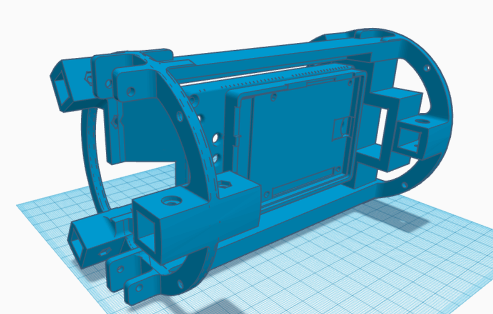

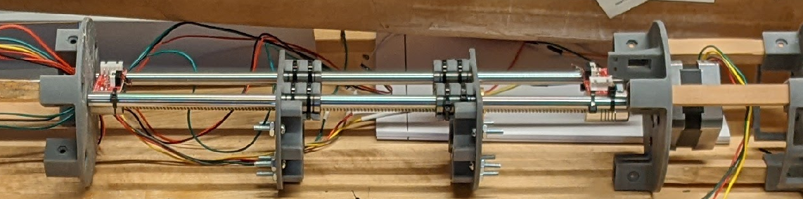 This is an image of half of the battery pack, simply print an additional Battery_mount_bearings and orientate it to face the others in order to fit all 12 cells.
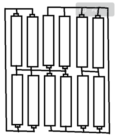 Solder on the BMS according to the KiCad file and insulate the power supply from the surrounding wires.
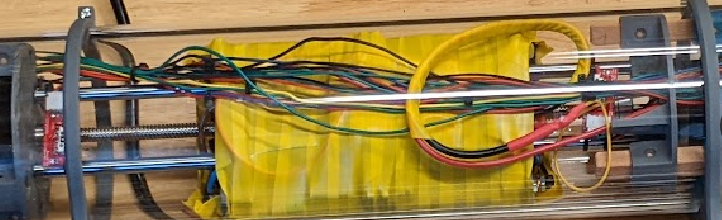 Add friction-less tape as needed. (Again this should be resigned so that there is no contact with the outer wall if possible)
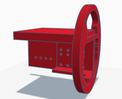 Connect the pump, solenoids and bladder. The vacuum pulled on the glider will pull water in, the pump will only be used to pump water out.
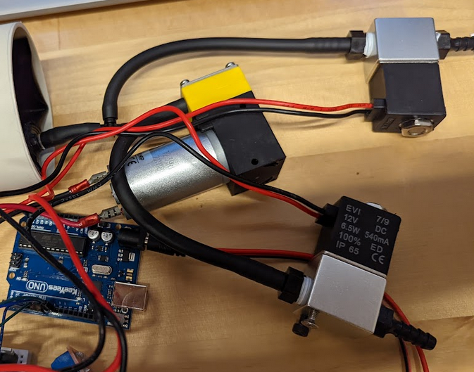 The Wiring diagram can be found in the KiCAD files. The bladder will be constrained by a PVC pipe. The bladder itself will be fitted with flex sensors which will be used to determine if the bladder is full or empty.
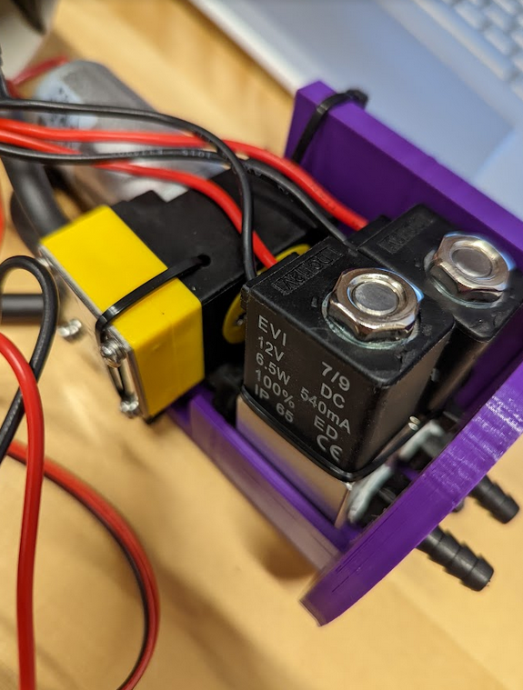 Depending on the print quality some light filing might be required as you can see above the parts were a bit too snug.
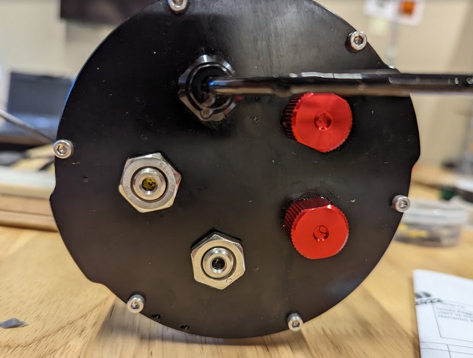 On the rear bulkhead connect a vent plug, two on plugs, the pressure and temperature combined plug and the cable perpetrator plug for charging. As seen in the Wiring diagram on of the on plugs will turn on the raspberry pi, the other turns on the 12V for the actuators.
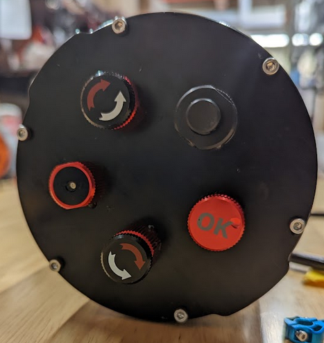 Once all of the plugs/penetrator's have been installed the bulkheads can be screwed onto the printed circuit rack and valve holder on either ends of the glider.
Discussions
Become a Hackaday.io Member
Create an account to leave a comment. Already have an account? Log In.