 Seth Fleming-Alho
-
Version 2.4
06/05/2023 at 17:06 • 0 commentsWork has resumed on the glider!
Having discovered a hydraulic pump option that can be acquired from hobby stores here we have returned to the 4inch tube design keeping cost and portability in mind. This pump is supposedly capable of reaching depths far past the crush point of our blue robotics acrylic hull but has yet to be rigorously pressure tested. The limit for depth on the glider at the moment its theoretically 40-50 meters of seawater, this is because we are still using the same valves as the previous iteration. Finding couplings to connect the 4mmOD 2.5mmID tubing for the pump to the 1/4" tubing and threads of the valve and bulkhead penetrators has been an ongoing struggle and it is likely a rework of the plumbing is in order. Once completed the hydraulic pump has the advantage of not only higher pressure but also keeping seawater out of the ballast engine by only using mineral oil which is a safer alternative to actual hydraulic fluid. Requiring not only an internal ballast but an external ballast means we have designed and external nosecone to contain the bladder and protect the altimeter. Water testing of various 3d printer materials is ongoing to see which will work best, our current iteration is a mix of PETG (internal) and ABS (external). We have stuck with using lifting bags to act as our ballast "tanks".The entire structure inside the glider has been redesigned. Only containing an Arduino mega (and a 1500MKR in the future for cellular communication) the rear cell compartment has been simplified. The pitch engine had to undergo large changes because under the transportation of dangerous goods acts it is illegal to manufacture and transport your own batteries. To work around this restriction the power pack had to be assembled in such a way that all of the individual 18650 lithium cells being used are separate and not welded together. The roll engine now also include bearings to promote a smoother rotation and remove the need for anti-friction tape. The ballast engine underwent a rework to house the bladder along with the new hydraulic pump and ESC to control it. As mentioned above the plumbing needs some better connectors and that is being worked on.
The glider now has the custom circuit board installed and while the individual modules are testing well the current converter to bring the 12V of the battery pack to the 5V for the logic of the circuit is unable to deliver adequate current and will be replaced with a 12V to 5V buck converter from a car.
The 9DOF board has been installed and works (mostly). The compass seems to not be very reliable, this could be due to poor calibration or external interference. More testing is required but we may be required to purchase a better compass module. However even with the poor accuracy the glider does now have navigation! Using an onboard GPS and the compass it can take a coordinate input and determine a heading and bearing and should theoretically be able to make it to the coordinate.
-
To Do List
08/29/2022 at 17:33 • 0 comments1.) The Hull
Having switched out the syringe ballast engine for the pump design we are considering a larger enclosure tube. We realized while looking for an adequate pump that most 12V pumps are just slightly over 4Inches in diameter and would hence not fit in the tube. Switching to a 6inch enclose would allow for a much wider range of pumps to be considered, most of which are far more powerful than what is currently inside the glider.
The 4" acrylic tube was used because it was part of the original design. 4" acrylic is great for prototyping since you can see what is going on inside, however, it is no longer available from Bulerobotics, was difficult to source, and was one of the most expensive parts of the project. In addition, it was very difficult to source a pump that would fit inside a 4 inch tube. Increasing the size of the tube to 6" should give enough room for a larger variety of pump options.
All parts for 6" enclosures are available from Bluerobotics (https://bluerobotics.com/product-category/watertight-enclosures/6-series/), however, the longest length available is 11.75"/298mm. Longer tube could be sourced elsewhere and doesn't need to be clear or acrylic. Options could include aluminum, PVC, etc.
2.) STL files
Increasing the size of the enclose will mean an overhaul of the printed files. Opportunities will be taken to increase battery capacity, install a larger pump and change the circuit rack design to either copy or use the prefabricated model from Blue ROV (along these lines https://bluerobotics.com/store/watertight-enclosures/locking-series/wte4-etray-r1/). The prefabricated circuit rack will only be viable if the glider design keeps the 4Inch tubing.
Currently the different sections of the glider are connected with wood for ease of prototyping however this will be replaced with long metal standoffs https://bluerobotics.com/store/rov/bluerov2-components-spares/standoff-m3x0-5-212-mf/.
3.) Cable connectors
The prototype wiring definitely needs some wire clean-up and ideally all connectors will be either soldered together or connected with clip-in connectors. These connectors will be introduced into the PCB design.
4.) Replacing the IMU.
Currently the glider operates off of a MPU-6050, this is unfortunately only a 6-DOF chip and for reliable navigation during the dead reckoning dives we require a 9-DOF chip. Testing has begun on the https://bc-robotics.com/shop/9-dof-sensor-stick/ to see if it satisfies our requirements.
5.) More Sensors
With and Arduino interfacing with sensors is incredibly easy and with a few open slots in the bulkhead it would be good to find sensors important to oceanographic work that could be easily installed.
6.) Ballast Volume Measurement
The whole ballast engine design is a pretty crude prototype, pretty good for the first version and a huge improvement over the syringe design. The big thing we need to figure out is how to measure whether the ballast is all the way in or all the way out and ideally some way of measuring/estimating the volume between those two extremes. Limit switches, pressure sensors, and the flex sensor (https://bc-robotics.com/shop/short-flexbend-sensor/) are a few options we discussed, but we should be open to other options including a different interior reservoir that would allow better measurement
7.) Remove raspberry pi
The pi and its separate power supply exist solely for being able to wirelessly reprogram the Arduino during the testing phase. It will no longer be necessary once the design and code are finalized. This will save room and reduce power consumption.
8.) Bladder
Ideally an internal and external bladder should be used. Unfortunately we were unable to source a fitting during this phase of the project that allowed tubing to be attached to both sides of the end-cap. Running the ballast engine with normal seawater will run the chance of the tubing or penetrators becoming clogged. Having an internal and external bladder filled with oil would be able to run without any risk of foreign materials getting sucked in.
9.) navigation, communication, and piloting interface
The glider currently has a simple interface where a single command 'dive' can be sent over a long range radio and the glider follows a pre-programed series of events to do a single dive.
Future improvements to communications could include: adding a cellular communications so the glider could be monitored remotely and ideally could receive commands. Having the glider send back data over radio or cellular, especially location
-
Roll Engine
08/23/2022 at 16:02 • 0 commentsThe .stl files from https://hackaday.io/project/20458-osug-open-source-underwater-glider originally call for a stepper motor and planetary gear setup (figure 1) in order to control the roll of the glider and to be able to steer. We had challenges getting a planetary gear setup working so a change was made to use a high toque metal servo (figure 2) that was mechanically more simple, easier to program and didn't require limit switches.
Figure 1
Figure 2
The main remaining issue is keeping the coupling from accidentally separating during pitch-motor movement. -
The Brains of the Glider
08/22/2022 at 18:28 • 0 commentsThe original plan was to use an Arduino for full control of the glider. Cellular communication could be established while on the surface and dead reckoning would be used subsurface. For prototyping purposes we opted to use long range radio control. We also wanted the ability to reprogram the glider quickly and without needing cables so it was decided that a raspberry pi would be included in the design. The Pi is used to control the Arduino and reprogram it on the fly through WiFi, this saves us from needing to open the glider for every adjustment. We also wanted the ability to power off any actuators while reprogramming to avoid any accidental damage so a second power supply was added purely to support the raspberry pi in the form of a portable phone charger.
-
Battery Enclosure
08/22/2022 at 18:21 • 0 comments![]()
The battery Enclosure design from https://hackaday.io/project/20458-osug-open-source-underwater-glider was modified to house 12 18650 Lithium cells in a 3S4p configuration to power the glider. The power pack also acts as a moving pitch weight to help the glider pitch down when diving and pitch up when surfacing. The original test of this unit showed it had too much friction between the batteries and the glider tube wall so some low friction blue tape was used. Changes in the design need to be implemented so that the power pack does not touch the glider walls, this will prevent unnecessary wear and power draw.
Here is a skeleton view of the pitch battery system.
-
Electronics Board Design
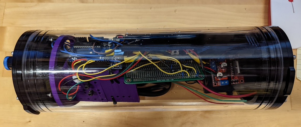
08/22/2022 at 18:06 • 0 comments![]()
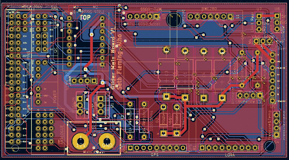
To avoid wires becoming loose inside the glider all sensors and motor drivers were soldered onto a pro typing breadboard. This kept the wires from disconnecting however it became a mess of wires so A PCB was designed using KiCAD to reduce the mess and encompass all the electronics into a single board.
-
Ballast Engine
08/22/2022 at 18:02 • 0 comments![]()
Initially the ballast engine was modeled after a previous build for an open source underwater glider (https://hackaday.io/project/20458-osug-open-source-underwater-glider). The syringe design was low cost and elegant however we quickly discovered that the syringes would bind and it did have a very low pressure rating despite upgrading the drive motor from a Nema-17 to a Nema-23. For this reason the ballast design was reformatted to use a High pressure pump combined with a reservoir. This would allow for the glider to reach greater depths and therefore become more energy efficient.
The following figure was a test of just the new pump design.
This design included two solenoid valves rated for 100PSI, a control board, and arduino uno and a diaphragm pump rated to approximately 30meters of seawater with a lifting bag as a bladder.
Choosing the pump was difficult as finding a pump that fit the power requirements (12V), the tube diameter (4inches) and had the power capable of pumping out water at depth proved to be quite a challenge and is a driving factor in potentially shifting to a 6inch tube for the 2nd version.
Once implemented into the glider the new ballast engine design preformed very well. The glider will need to be ballasted but this engine design should be able to descend to 15 to 20 meters.In this image the wings have not been attached and the altimeter is hanging loose as the nosecone is also off for testing purposes.
Open-Source Shallow Water Glider
With support from Fisheries and Oceans Canada as a part of a co-op work term
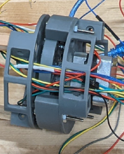 Figure 1
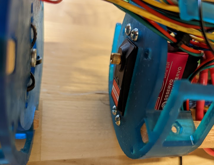 Figure 2
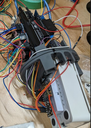 The original plan was to use an Arduino for full control of the glider. Cellular communication could be established while on the surface and dead reckoning would be used subsurface. For prototyping purposes we opted to use long range radio control. We also wanted the ability to reprogram the glider quickly and without needing cables so it was decided that a raspberry pi would be included in the design. The Pi is used to control the Arduino and reprogram it on the fly through WiFi, this saves us from needing to open the glider for every adjustment. We also wanted the ability to power off any actuators while reprogramming to avoid any accidental damage so a second power supply was added purely to support the raspberry pi in the form of a portable phone charger.
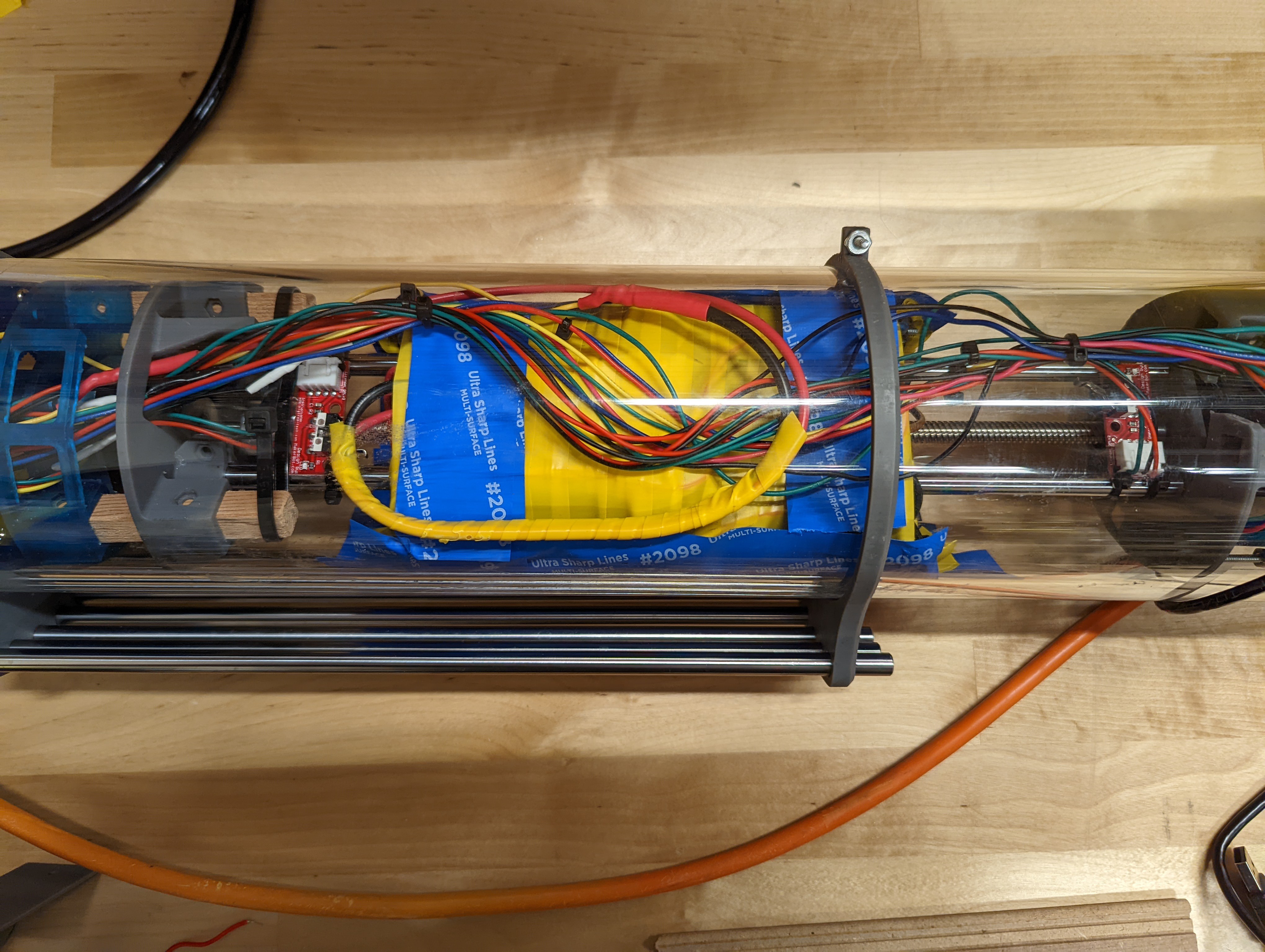
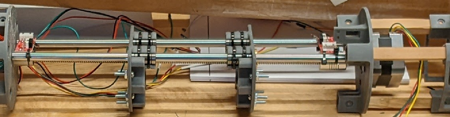 Here is a skeleton view of the pitch battery system.
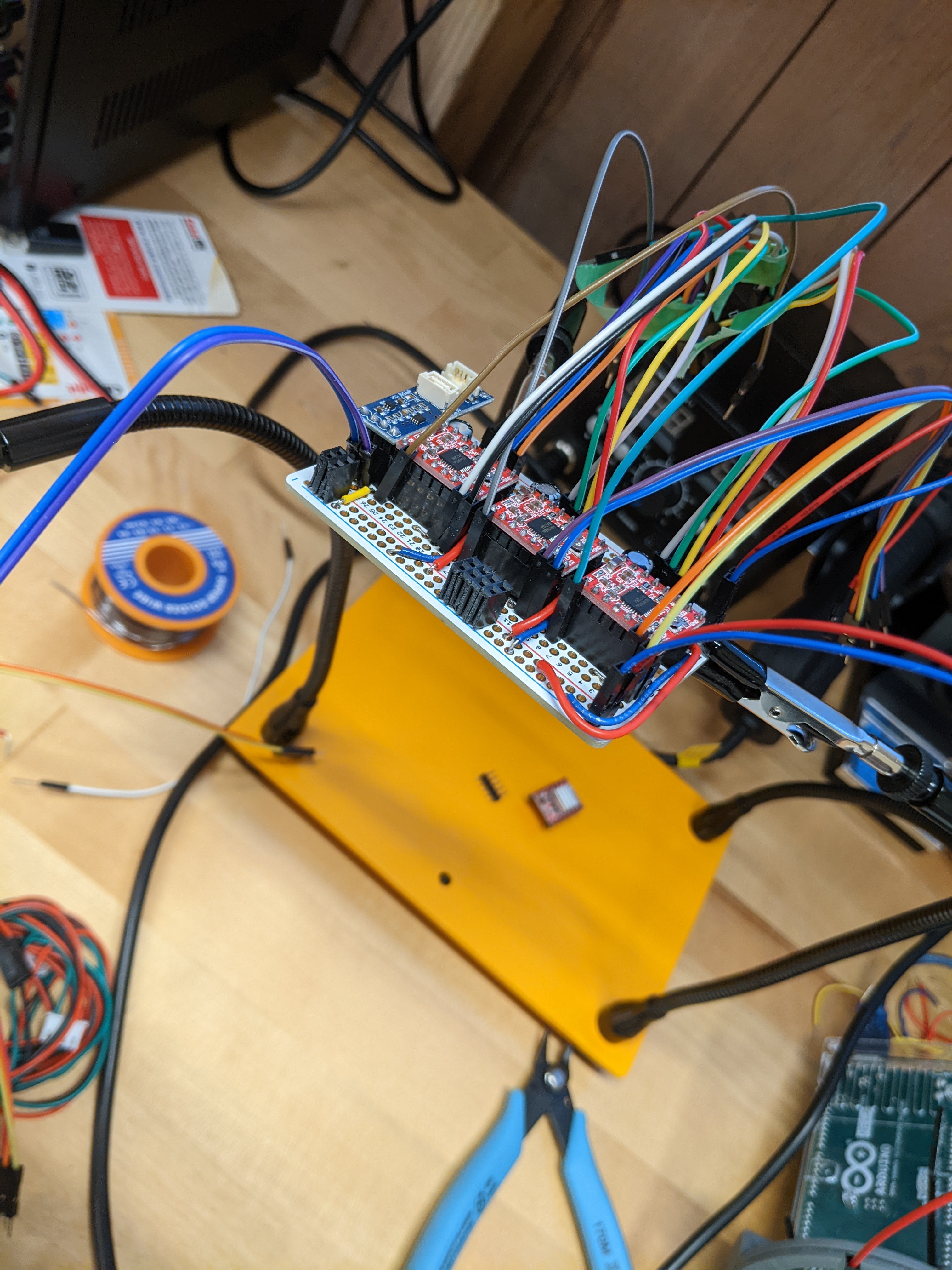
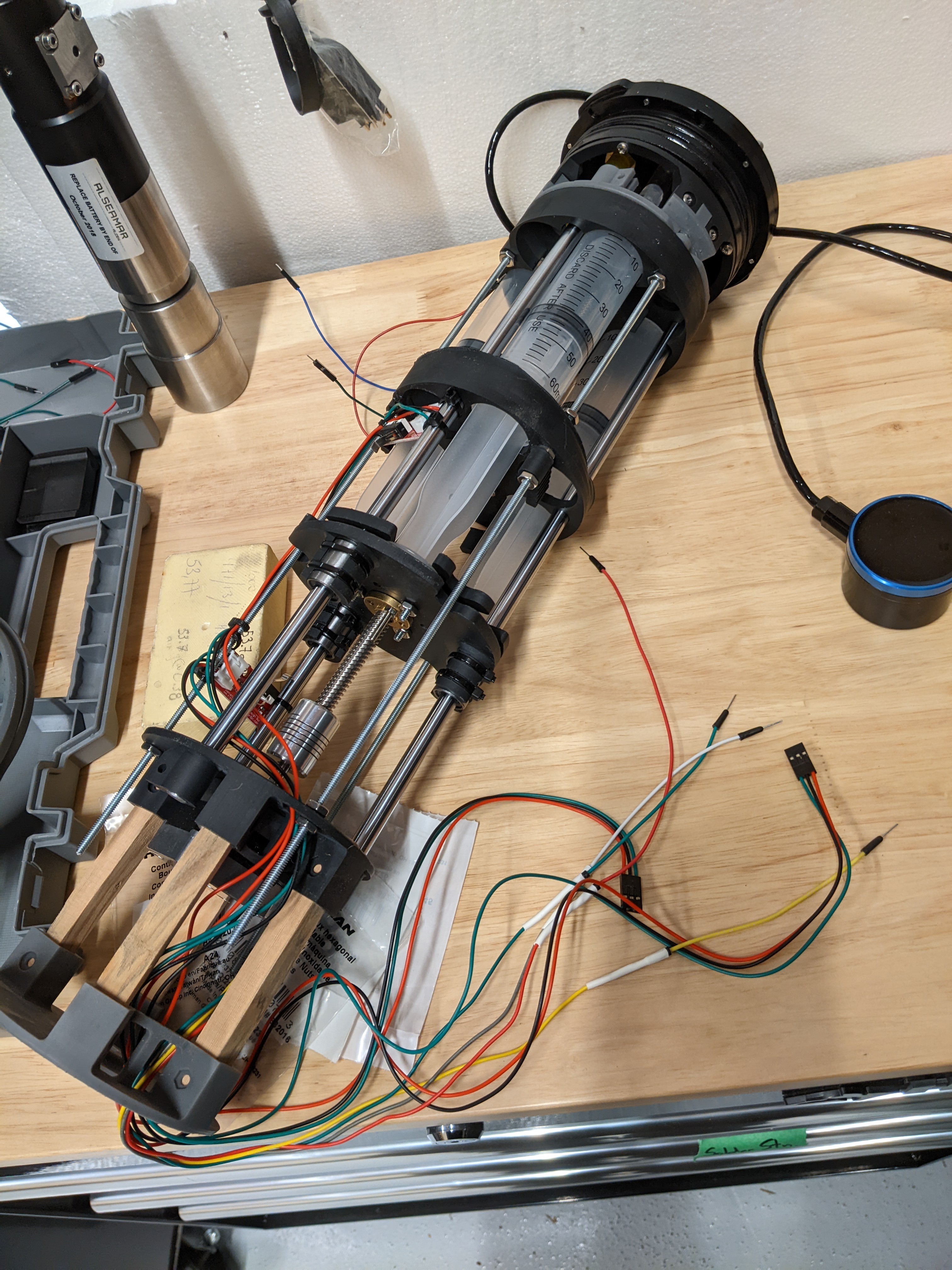
 This design included two solenoid valves rated for 100PSI, a control board, and arduino uno and a diaphragm pump rated to approximately 30meters of seawater with a lifting bag as a bladder.
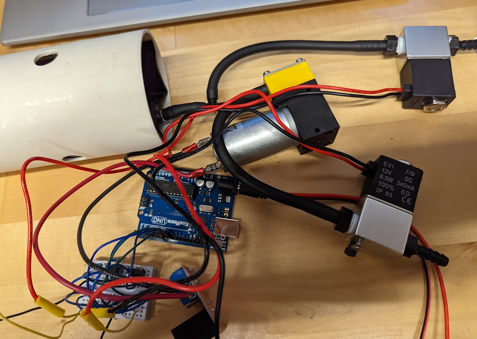
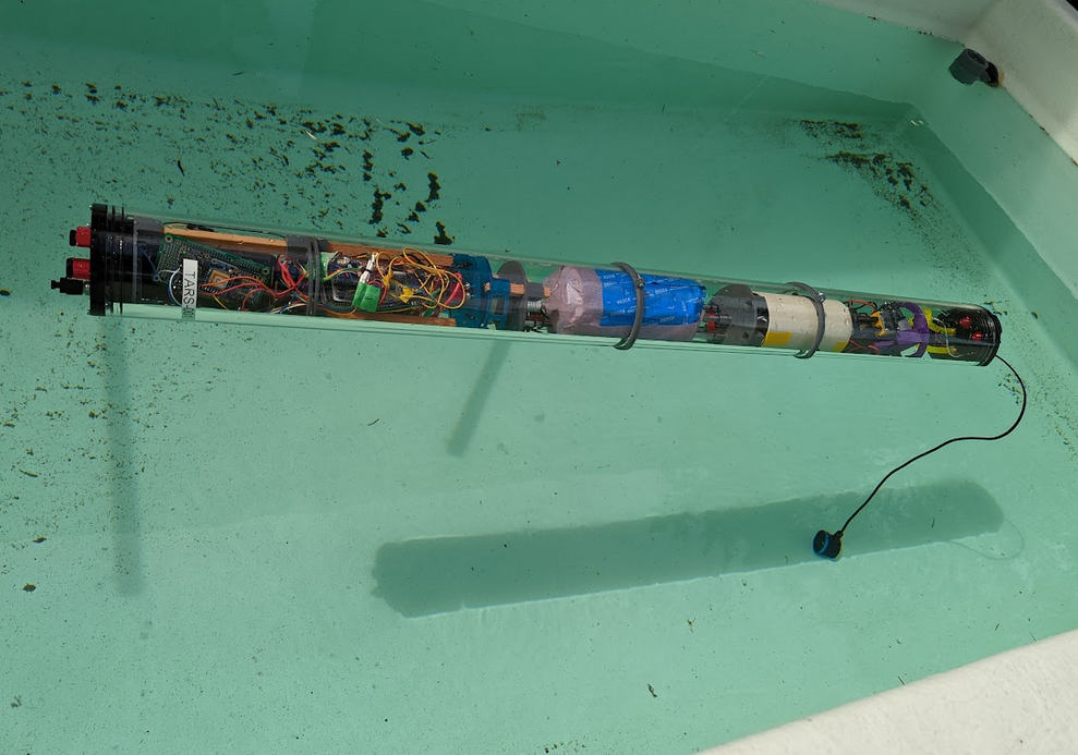 In this image the wings have not been attached and the altimeter is hanging loose as the nosecone is also off for testing purposes.