Michael Gardi
-
Building the Frame
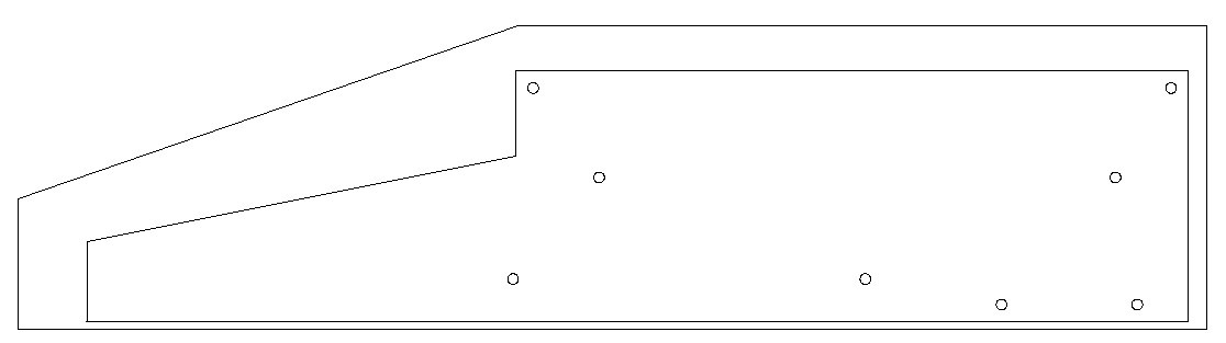
12/12/2022 at 02:04 • 0 commentsSo I used the models based on Steve's measurements to create a DXF file to cut out the side panels.
![]()
The inside panel has holes defined that will be used to join the inside panels to the cross-bars that will separate them at the correct distance apart, and there are also holes to connect the outside panels to the inside panels. Using 1/8 inch plywood I laser cut one piece exactly as above with the inside panel nested within the outside (thanks kwartzlab), then I cut three more inside panels only.
I glued pairs of inside panels together so I had two 1/4 inch inside panels. I then used the outside cut panel as a template to layout the two outside panels on a nice plank of 1/2 inch walnut. These I cut out with skill and jig saws and used a belt sander to smooth the edges.
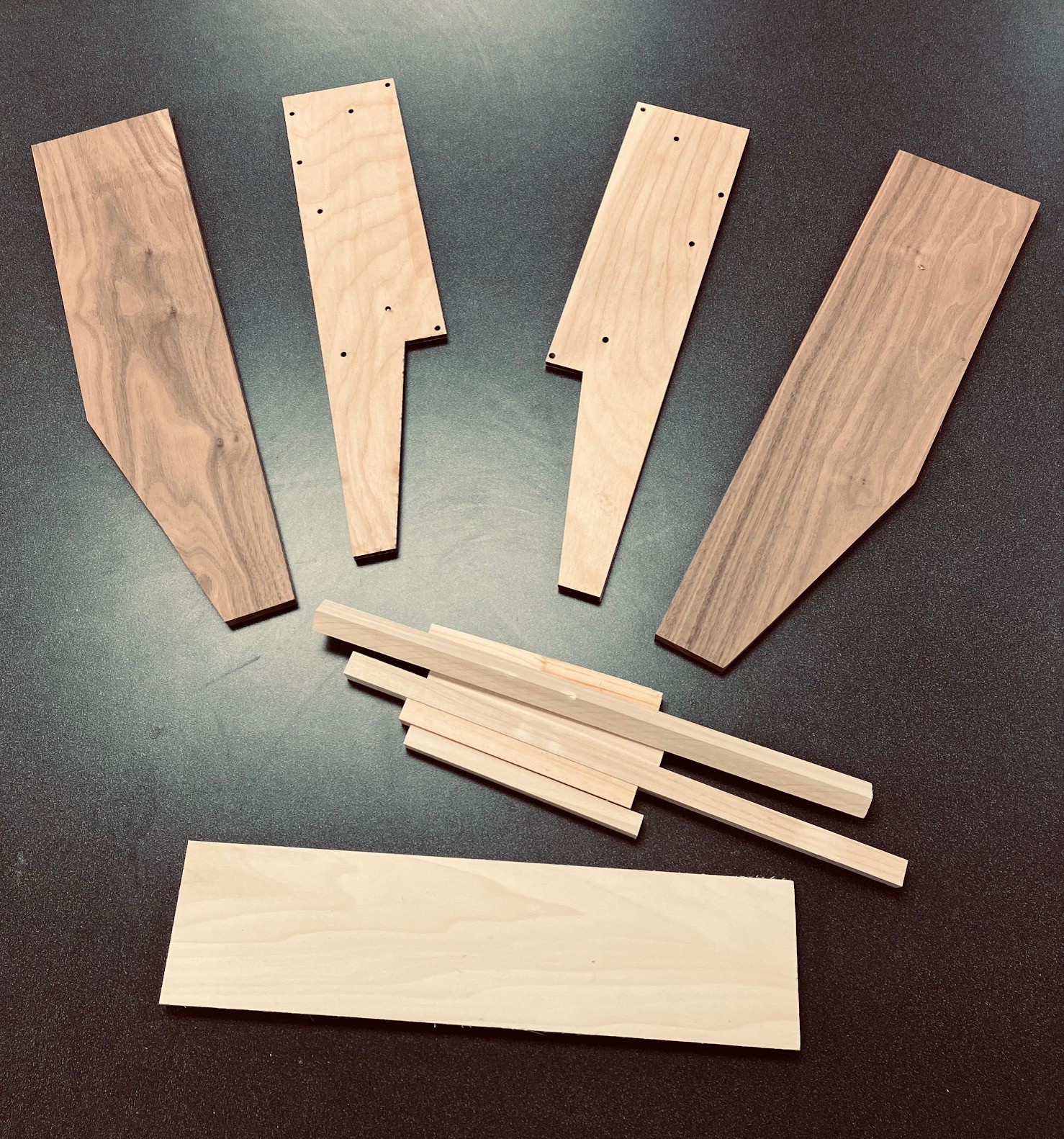
Finally I cut out some cross-pieces 364 mm long. One was 1/2 x 4 inch pine, plus two 5/8 inch square dowels. In addition I cut four 130 mm lengths of 1/2 inch dowel.
So here is was I ended up with.
![]()
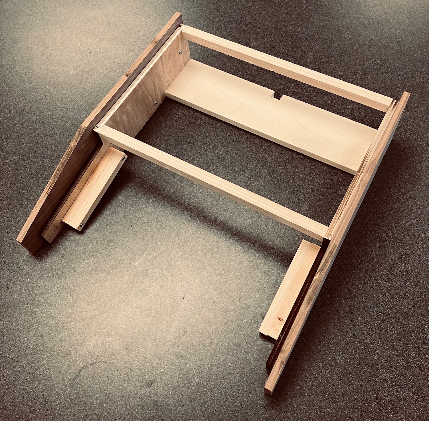
I attached the cross-pieces to the insides with #6 - 1 inch wood screws making sure the the heads were flush with the panel. The shorter 1/2 inch dowels were doubled up attached to the inside of the side panels at 20 mm below the slanted edge to support the keyboard.
Finally I used the outside template to properly align the inside pieces to the outside and joined them with 5/8 inch wood screws.
![]()
Also notice that I cut a 10 x 10 mm notch into the back of the 1/2 x 4 inch cross-bar to accommodate a support beam on the case.
I've started printing the case pieces. I will have to print six separate pieces that are small enough to fit on my print bed. To facilitate the reconstruction I have added support beams underneath with holes so I can bolt the separate pieces back together again.
![]()
All together there is about 50 hours of printing ahead of me.
-
Modelling the Case
12/08/2022 at 20:28 • 0 commentsWhen you don't have an original to work from, it is often difficult to create a reproduction. There are usually lots of photos available online, but they don't give any indication of the case dimensions. Often I am helped by enthusiasts that own an original and are kind enough to share some measurements and photos with me.
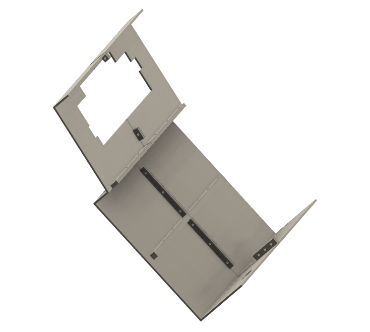
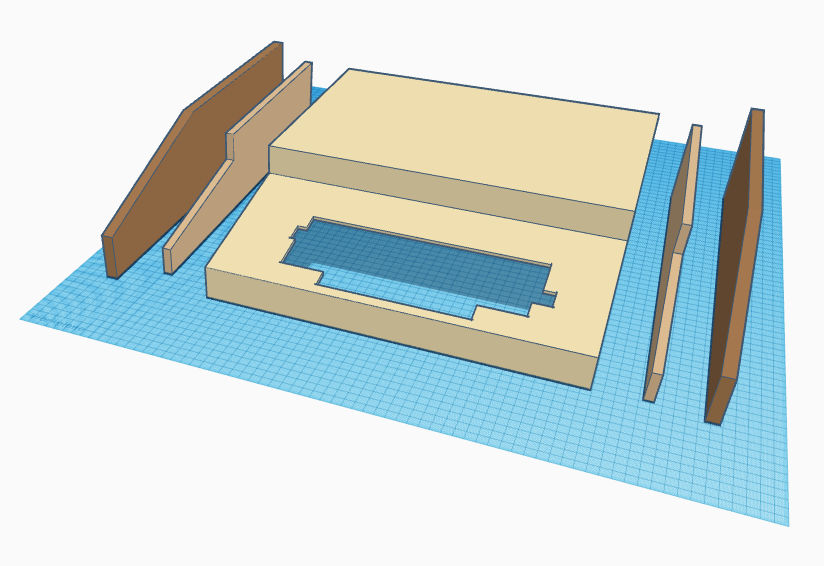
Fortunately for me there is a robust Ohio Scientific community out there. A great place to start is Dave's OSI Page. This was an invaluable resource when I was creating the 1P (4P) emulator. For the case, Dave himself pointed me at a thread in the OSI Discussion Forum where a participant name Steve Gray posted all of the very measurements I was looking for. Using Steve's measurements I modeled some case parts.
![]()
I will probably laser cut the "inside" side pieces, CNC the "outside" side pieces, and 3D print the case skin.
-
Keyboard Assembly
11/03/2022 at 09:35 • 0 commentsI've kind of been in a holding pattern waiting for the keyboard "kit" to arrive but no more as it was delivered last week. This is a classic retro-style ASCII keyboard, modeled after the ADM-3A keyboard, which can also be populated to fit perfectly in an Apple II/II+, or an Ohio Scientific Inc. computer. For details check out the Unified Retro Keyboard project.
I was able to purchase the keyboard PCB, a set of Fubata MD-4PCS keys, a stabilizer panel for the Fubata keys, and a set of reproduction OSI keycaps from Dave at osiweb.org. I also ordered an OSI specific encoder which is on backorder.
So I went ahead and assembled the keyboard. I'm not going to detail the process here since it was mostly identical to the work I did on my Sol-20 Reproduction. For details check out:
- The Keyboard Encoder
- Keyboard Construction (Note that the newer keyboard PCB has the discrete diodes and resistors pre-populated on the board. A real time saver. Thanks Dave.)
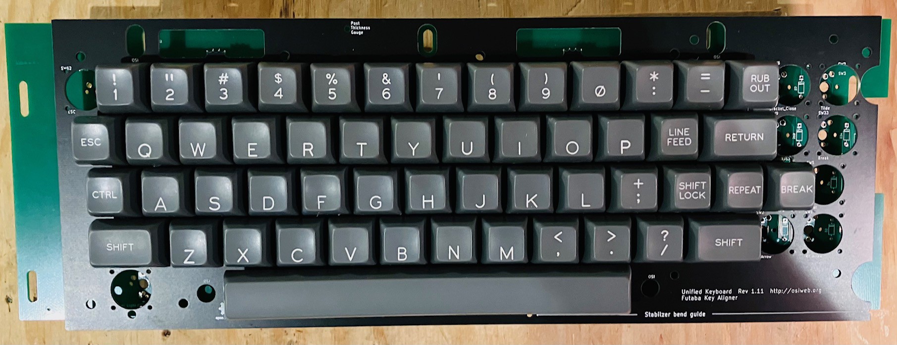
After adding the OSI Challenger style keycaps this is what I have.
![]() Now I just need a case to put it in.
Now I just need a case to put it in. -
To 1P or 4P, That Is the Question
10/31/2022 at 17:27 • 0 commentsOver the course of their six year run from 1975 to 1981, Ohio Scientific sold a wide range of computer products from the low end Model 500 single-board computer to high end Challenger III disk based business systems selling for $13,000 or more (in 1970s dollars).
The lowest cost OSI offering was the Superboard II, a compact and simple single-board computer. This entry-level system featured a keyboard, video display, audio cassette, BASIC-in-ROM, and up to 8K RAM for around $300. The Challenger 1P was basically a Superboard II with a case and power supply. Both were part of the Ohio Scientific Challenger 1 Series.
In 1977 Ohio Scientific launched a number of systems in their Challenger 2 Series, the smallest of which was the Challenger 4P. Similar to the C-1P but on a standard OSI 48-pin bus, this system is composed of separate boards including a 6502 CPU board, a 540 video card, and a keyboard all mounted in a nice case. With a newer graphics card than older systems, featuring a whopping 2K of video RAM, a 64-by-32 character display was supported.
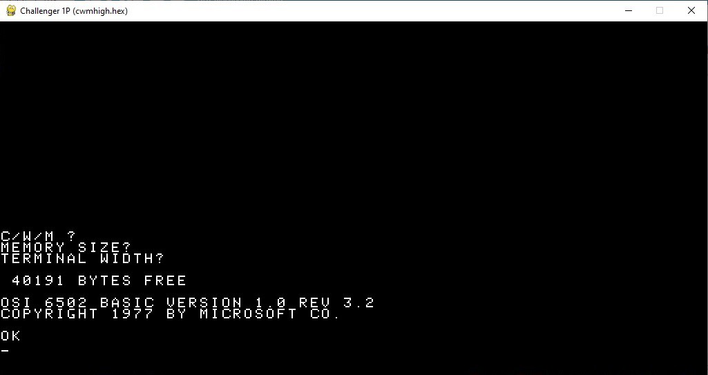
My original intent was to do a Challenger 1P reproduction, however I am finding that the 32x32 character display (24,24 actual) is a bit limiting. Since a bare bones Challenger 4P system is similar to the 1P but with a 64x32 character display I feel this might be a better choice. To that end I have updated my emulator to support the 4P in addition to the 1P. You can switch back and forth by selecting the appropriate monitor rom at startup (cwmhigh.hex for the 4P or synmon.hex/cegmon.hex for the 1P).
![]()
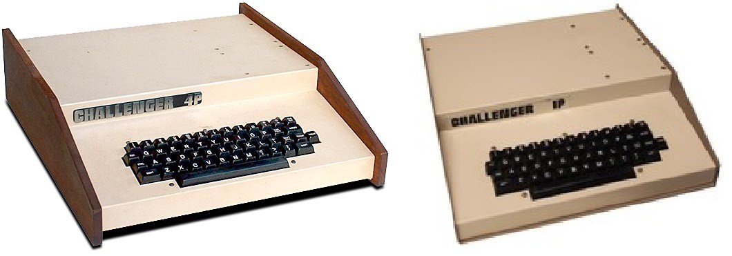
There is another reason for choosing the Challenger 4P model for reproduction. The cases for both systems are quite similar but not quite identical.
![]()
The Challenger 1P on the right has a base and sides made out of a single U shaped piece of metal. IMHO this does not compare to the beautiful wooden sides of the Challenger 4P. I actually have a nice piece of walnut that would work really well. So the case will be built as a 4P with walnut sides, but of course will be selectable for 1P or 4P emulation.
All of the above changes have been posted to this projects GitHub repository.
Updated 12/15/2022: I have changed the project name and description to reflect the change in direction from a Challenger 1P to a Challenger 4P reproduction.
-
Better Load and Save Screens
08/30/2022 at 22:32 • 0 commentsWhile the Python/tkinter based load and save panels work OK, the windowed popups are disconcerting and would not be suitable when my Challenger 1P reproduction is working with a full screen text only display. So I created some "integrated" replacements. Now when you press F1 or F2, my emulator saves the current screen, "takes over" the display and keyboard, and uses them to present the user with Load and Save dialogs. When you exit the dialogs by pressing the Return key, the original screen is restored with the appropriate file names set behind the scene just as with the tkinter dialogs. Loading and saving has not changed and is implemented through the Challenger 1P cassette interface.
So as not to create too much work for myself I tried to keep the screens as minimal as possible. I think that the aesthetic is in keeping with the other period screens.
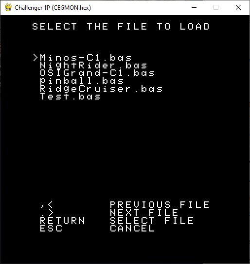
The load screen looks like this:
![]()
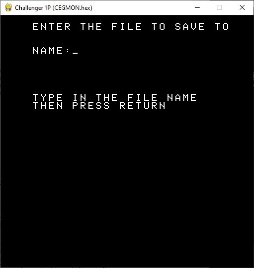
It supports a scrolling list of any number of file names. The files listed must be located in the TAPEs folder and only files with a .bas extension will be shown. Similarly the Save screen looks like:
![]()
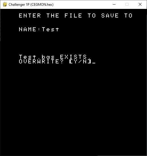
Simply type the file name in and press Return. If the user does not add a .bas extension one will be added on their behalf since only BASIC files can be loaded or saved. There is an additional check to see if the file name entered already exists. If it does:
![]()
Only pressing the 'Y' or "y" key will allow overwriting. Any other key and the user will have to start over.
All of the above changes have been posted to this projects GitHub repository.
OSI Challenger 4P Reproduction
I am making a full sized Challenger 4P reproduction, a 6502 based personal computer from the late 1970s.