Alvaro Barcellos
-
too complex setup of dip switches
09/25/2023 at 21:30 • 0 commentsToo complex setup and sensible to wrong selects at dip switches. Doing a review.
-
Still waiting
02/02/2023 at 13:30 • 0 commentsStill waiting components arrive.
Going to make a prototype for 64kb FLASH or EEPROMS, without high voltage operation ( 12.5V erase and 14.3V program), with dual serial bus, for address with three 74hc595 and for data with a 74hc595 and a 74hc165.
todo: support for high voltages, also SPI and I2C FLASH chips.
-
updates
09/14/2022 at 14:25 • 0 commentsDone small changes:
No more choice to use high address A16-A23, all bits goes for address A0-A23 by the shift registers.
Support for A27E257 eeprom 32kx8bits, changed dip-switches setup, as pin 1 is VPP, 12.75V to program, or VPP2, 14V for erase, and pin 28 is VCC.
New schematics v03.
Circuits for VPP and VPP2 not included.
-
software redux
09/09/2022 at 15:03 • 0 commentsthe software will be based on:
(this list could grow :)
https://github.com/beneater/eeprom-programmer
-
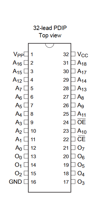
reference pinout
09/03/2022 at 15:19 • 0 commentsAs reference pinout for ZIF socket, prefer AT27C040:
![]()
Considering the first 8 pins ( 1, 2, 3, 4, 37, 38, 39, 40) reserved for I2C and SPI, then changes are:
ZIF REF A B NC 5 1 VPP A18 NC 7 3 A15 A14 VPP 35 31 A18 WE NC 34 30 A17 VCC NC 33 29 A14 WE NC 32 28 A13 VCC NC 29 25 A11 WE X 28 24 OE VPP X 20 16 GND GND GND PS. NC for not connected and X for must be, GND included for mark.
the schematics altered to comply.
dip switch 01 and 02 for eeproms:
to review:
AT28C16, (01 ON: S6, S8, S9), (02 ON: S3)
AT28C64, (01 ON: S2, S4, S7, S9), (02 ON: S3)
AT28C256, (01 ON: S2, S4, S7, S9), (02 ON: S4)**
SST39SF040, (01 ON: S1, S3, S5, S7, S9), (02 ON: S3)
M27C512, (01 ON: S2, S3, S5, S7, S10), (02 ON: S3)
W27E257 to review
AT24CXXX ALL OFF.
update:
for W27E257 pin 1 is VPP and pin 28 is VCC
-
serial pins
09/02/2022 at 22:06 • 0 commentsTop 8 pins
The top 8 pins pins-outs of zero-insertion-force (ZIF) socket, are reserved for I2C and SPI, : with follow setup.
SPI I2C PIN PIN I2C SPI /CS S0 1 40 VCC VCC SO S1 2 39 WR /HOLD /WP S2 3 38 SCL MSCK GND GND 4 37 SDA MOSI OBS.
pull-ups 4k7 resistors at (S1, S2, SDA, SCL, WR) and pull-down at S0.
I2C or SPI must be select for use, or go in tri-state.