I just found this animation and thought it was particularly intelligent, especially the folding animation to show that they went for a totally internally reflected path to shave even more thickness on the optics.
It does seem that the light efficiency has been increased over the traditional birdbath too since the light gets halved twice (so only 25% makes it to the eye). Below are some of the paths the light will take
Since the whole system is reflective, there's no opportunity chromatic abberations either.
Looking at the actual device, it kinda seems like something that might be theoretically possible to print on the #SecSavr Suspense [gd0105]:
But that sounds like having to print stainless steel and glass (or some high temp transparent material due to the sintering of stainless steel) in the same print, along with polishing gear in the Brick of Innovation to get this kind of finish:
I've hopefully got a new solution for the optical pathway, and I should have a better understanding of how things should work out.
For an 18.4mm active area and intending to use 4:3 virtual monitors, the visible diameter is 23mm.
The 55mm fresnel lens is F-30, though this and everything else likely would change because I haven't taken the users head into consideration and the rays might be intersecting it.
The lens straight after that is the D42 F-40 I've already got.
The mirror is likely to be slightly tilted so that the optical elements after that are parallel with the top slope of the helmet, but for now I'm just using a 90 degree bend in this simulation.
Then there's 2 double convex lenses that obtain the 23mm focus disk.
Tracing backwards from the screen, it seems that the centre of the eyebox will see a slight dimming of the edges. If the eye is closer to the edge of the eyebox, the centre of the virtual monitor may appear dimmer than the edges. OLED has some good viewing angles though so I don't think this should be a critical issue.
The entire optical path + screen would likely fit under 40mm from the front of the eye, which is probably on or near the ear/scalp circumference of the head.
With the exception of the aspheric fresnel lens, the rays mainly cross though the inner 50% of the lenses which hopefully will reduce abberations.
The second lens is exposed (it'll be partially sticking out of the inner helmet "ceiling") and very close to a focal point. This could mean that dirt on the surface of the lens would be visible.
A possible thing that is incorrect is that I'm using the 10mm eyebox. Maybe I'm supposed to use the larger 12.5mm diameter FOV circle (see below) or be using 18.4mm as the screen size in the simulation instead of 23mm. Maybe this just means the actual eyebox is 10mm * 10/12.5 = 8mm, which should still be servicable.
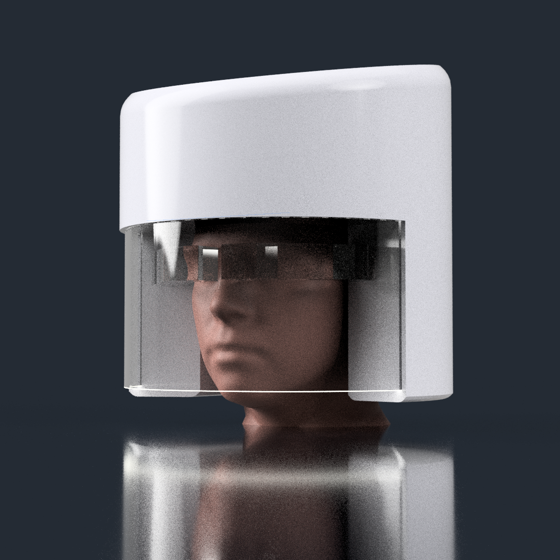
It actually looks... kinda smart looking. I haven't modelled it in, but just imagine there's 2 curved sticks maybe 5-10mm in diameter on the edges of the optics to hold them:
Ensuring that I've got >22mm of eye relief, I've angled the combiner inwards by 5 degrees so that the 55mm fresnel lens is optically centered (as apposed to a 50mm lens with very tight tolerances or an uncentred 55mm lens).
The 60mm combiners give ample space for the FOV desired, but a 55mm one might just about work too:
It's likely I'd get a bit of visual blur on the edges of the combiner, so 60mm is likely the visually better choice.This oval visually looks more tame from the 3rd person perspective too. It looks more like a cleanroom lab guy than a disco kid.
It's really seeming like 32 degrees of FOV is right on the edge of what's possible with the basic optical path I'm currently trying. Considering that I'm supposed to be aiming for 90PPD and not 80 anyway + the 2560px display is the highest available on the market, I'll try 30 degrees; a marginal difference that could make all the difference. This results in a PPD or around 85 which hopefully is the ideal compromise of feeling sharp and large at the same time. The 2160px would have a 25 degree FOV.
Unfortunately, the backlight for the 2160 panel is likely too dim for this application. I might have to see if it's possible to replace it with a more powerful LED, but that could add even more size to an already relatively large screen. Additionally, the display's contrast would be even worse than the 800:1 already rated. Obviously, the biggest issue is the size, and 2 fresnel lenses in the system make for a rather blurry image it seems, so I'd have to distance the screen to avoid vignetting. I think the allure of a £20 screen might result in the project getting thrown under the bus or pushed back months. Oh, and the £83/each driver board really doesn't help. £200 for dim screens with sub-desired resolution and undesired size isn't exactly easy to swallow. The contrast is probably fine since there'd be a 40 or 50% passthrough of light anyway, reducing contrast even for OLED.
I have limited time and a lot of projects, so it seems that my simple yet inescapable choice is to use the 2560px screens going forward, likely pushing the BOM to the £1,000 and up club.
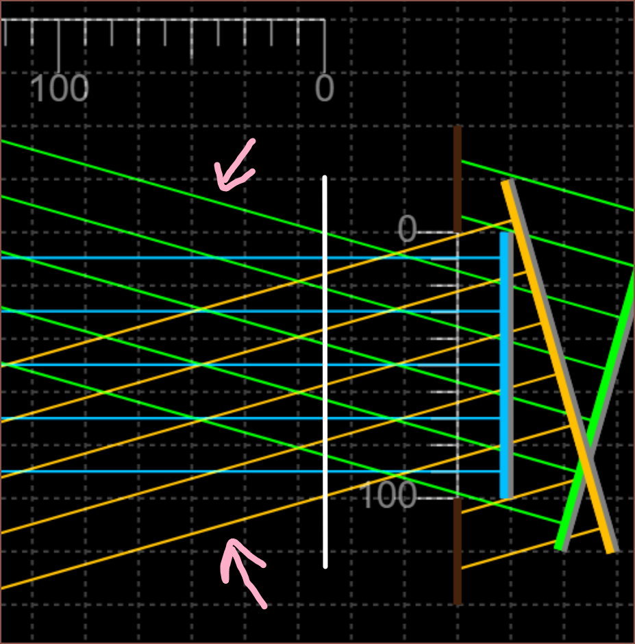
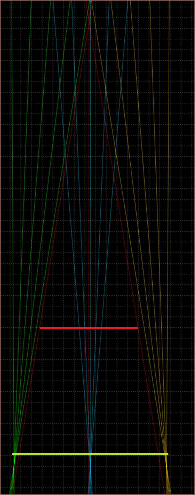
So, by enabling "simulate colours" and aligning 2 "beam"s to have the same angle as +/- 16 degree (and blocking out the excess), I was able to get rays that look like the optical rays diagrams I've been seeing in AR diagrams such as this one I've recently seen:SourceThe first time I saw ray diagrams like these, they used red, green and blue colours. I originally thought it was to test for chromatic abberations (in english: colours seperating into wavelength components) because it's the same as the RGB emited by all non-Porotech DPT screens. Then I reasoned it was just to get FOV understanding.
Now, I'm estimating that this is used to see both FOV and focus, along with confirming the eyebox.
The white line is where the eye starts. I'm going for a 10mm eyebox (the scale in these simulations is 10 units : 1mm) and the lines pointed to by the arrows is the cone of light I care about.
As you can see, each slightly different colour set of rays are parallel. This means that the intended focus is infinitely far away. I've also used colours slightly different from RGB to prevent personal confusion.
I think that the focus point is juuuuust behind (or infront) of the locationwhere the rays merge together into a point. This is because the pixel isn't an infinitely small point. The rays are also used to see the distance and size of the screen when focused at infinity. This is a notable difference to where I thought this location would be. Let me add a red beam to show you what I was doing before:
It's slightly misaligned but it's close enough for a description.
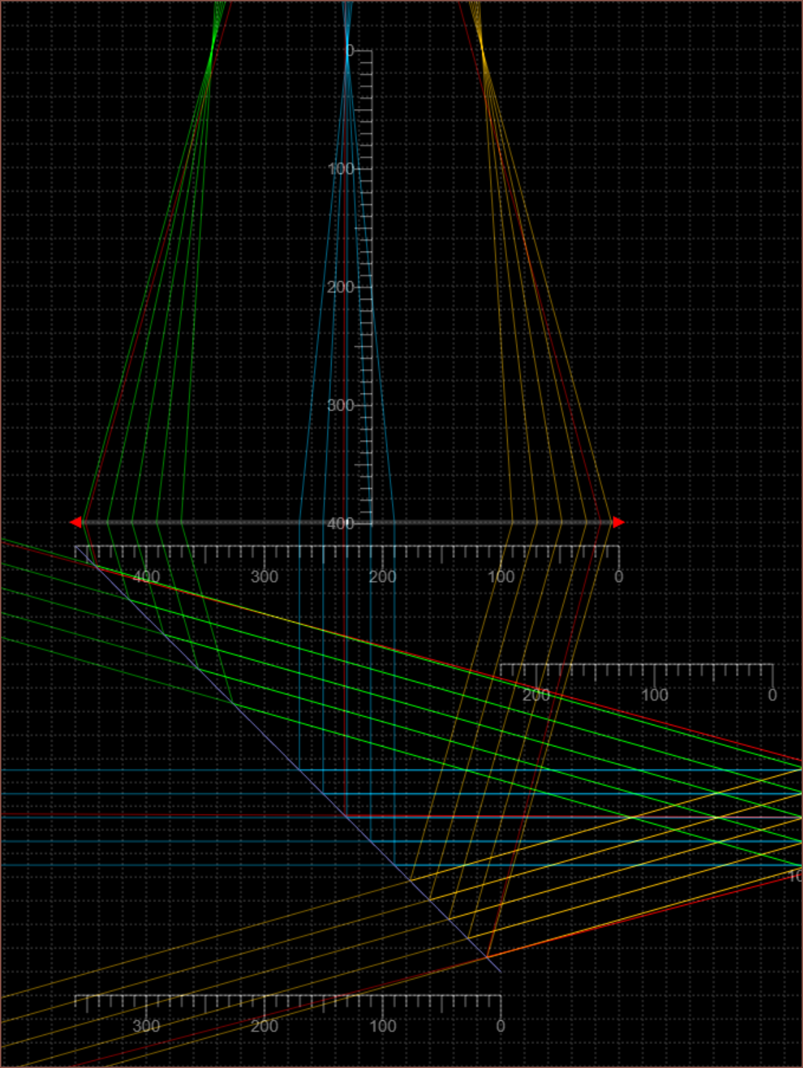
The lime green line is a screen with the right focus but wrong size, and the red line is the 18mm 2560px display size. Looking at where the actual FOV lines are, I would've misplaced this even further back. So, technically, the screen at the red location would've taken up my entire view, but that would've only been with 1 out of the 5 rays. The other 4 rays, likely originating from a black wall or something that isn't the screens active area, would make the edges mostly wall. At the same time, the centre is getting light from a wide part of the screen, so all those rays would get blended too. What would this look like? A stereotypical blurry blob of light that blur-fades into darkness the closer to the edges I look.
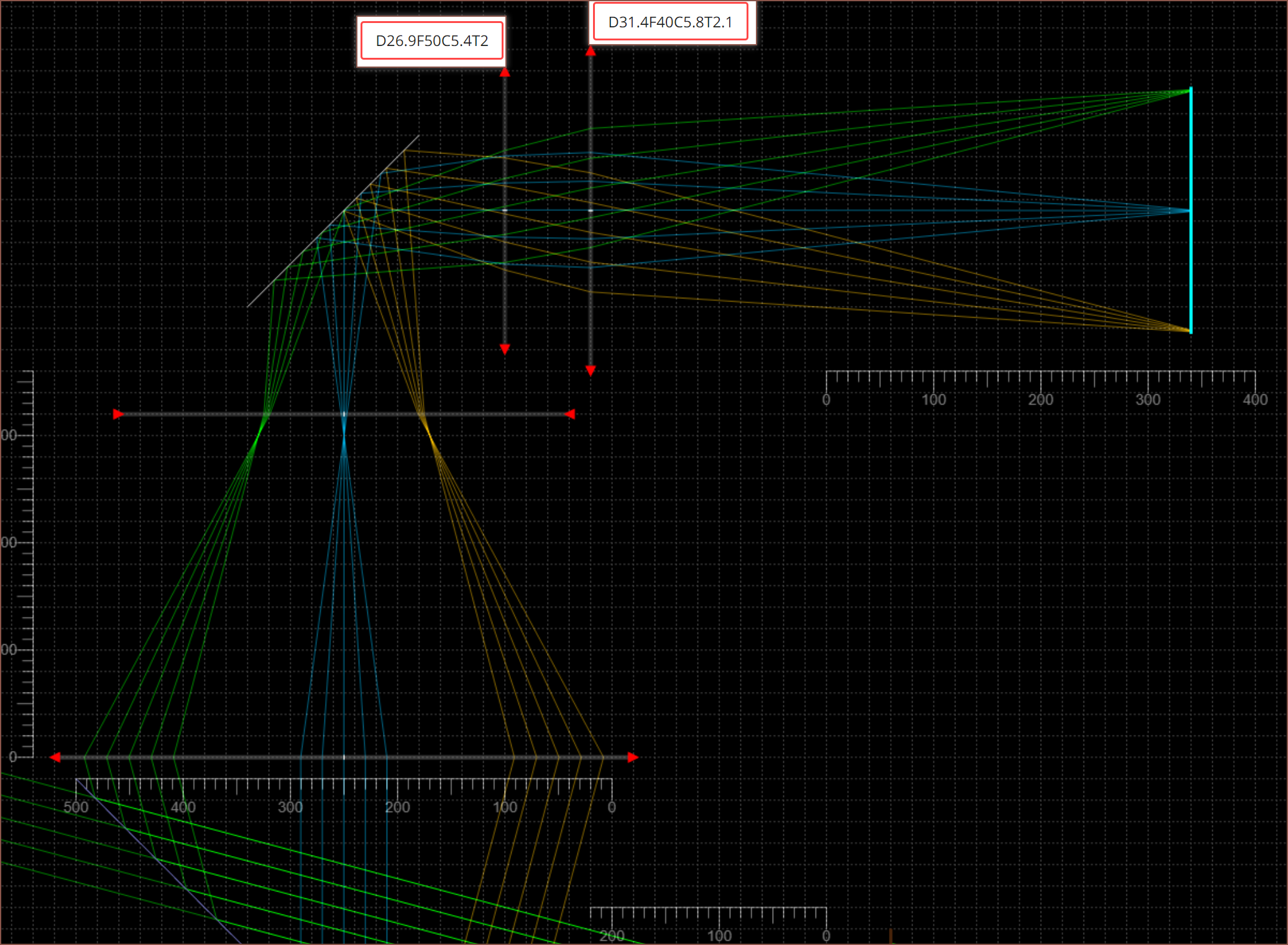
The below image is with a lens focal length of 80 instead of 50. In the first simulation, I would've thought that this would collect parallel rays (red) but no there's a (wider than the lens) location where an item would be in focus:
Well I've got some lenses so I might as well see if my hypotheses are correct or not. The below is F-30 and indeed if I look though the lens I actually have with my eye set to infinity, it just looks like a blur at any distance:
What about F40?
Allegedly, if my eye is 60mm away from the lens and the image source is 40mm behind it, I should be able to see it at focus=infinity.
Wow. I just looked using the placeholder 40mm beamsplitter prints and can indeed confirm that the focus, FOV and eyebox are probably correct. Magical. No... scientific!
So I got a 12" (305mm) ruler to try and imagine the kind of size this helmet would be like. It feels like I could really use an AR headset to help design this HUD helmet that might become an AR headset in the future as a sort of stretch goal. Suprisingly, the UK going rate of the Magic Leap 1 has plummeted to like 10-13% of it's MSRP.
To be honest, the price anchor of £2000+ MSRP wore off after about 5 minutes, and the single reason is due to the low resolution. If I'd never heard of Magic Leap or this was some AliExpress manufacturer, I'd be like "expectable price". I mean, it also includes the computing power too so that's why it's still in my mind.
Moving on, it does seem that, if I'm to use the 300mm tube visor, it can't extend much past my bottom lip or else my natural neck angles will be compromised. It seems that 150mm or so would be ideal, but that length isn't available. Since I need to cut it anyway, I'm thinking of getting a 305mm length (that costs £107) and cutting it in half.
I'm also considering using a perforated metal instead of acrylic. I'd have to make a jig to bend it into a tube and it would let in less light than acrylic, but due to diffraction it might be possible to see decently well though. The PLDC will be adhered onto the inside of the bent metal so that I could actually use the metal as a face shield in the event of a trip+fall.
I'm looking into circular beamsplitter elements and-- actually it'll be easier to explain if I just modelled it.
[about 20 minutes later...]
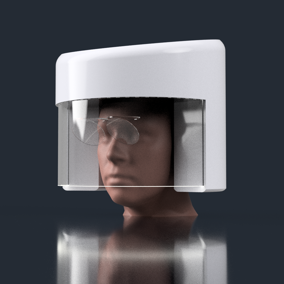
Wow... I uh didn't expect that modelling to go perfectly straightforward. I was expecting that the 40mm reflectors I had in my mind would still conflict with the door or the face but I've just fit a 60mm set in there super easily without any inconvinience. And angry-eyebrows aside, it actually looks organinc like a Spiderman mask.
The idea is simple.
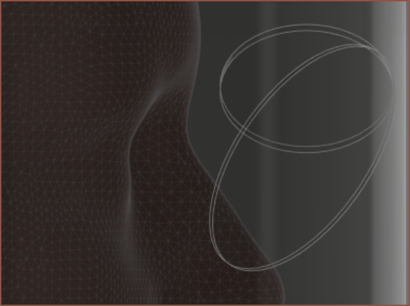
First create the beamsplitter and fresnel lens. The lens here is 40mm so maybe it's possible to find a non-fresnel alternative for higher image quality.Next rotate the front face 45 degrees and move the assembly forward until the lens misses the forehead:
Mirror for the other side. The idea is that the right display is responsible for the left eye and vice versa. I might try and see if 50mm is posible since the edges of glasses might get in the way.
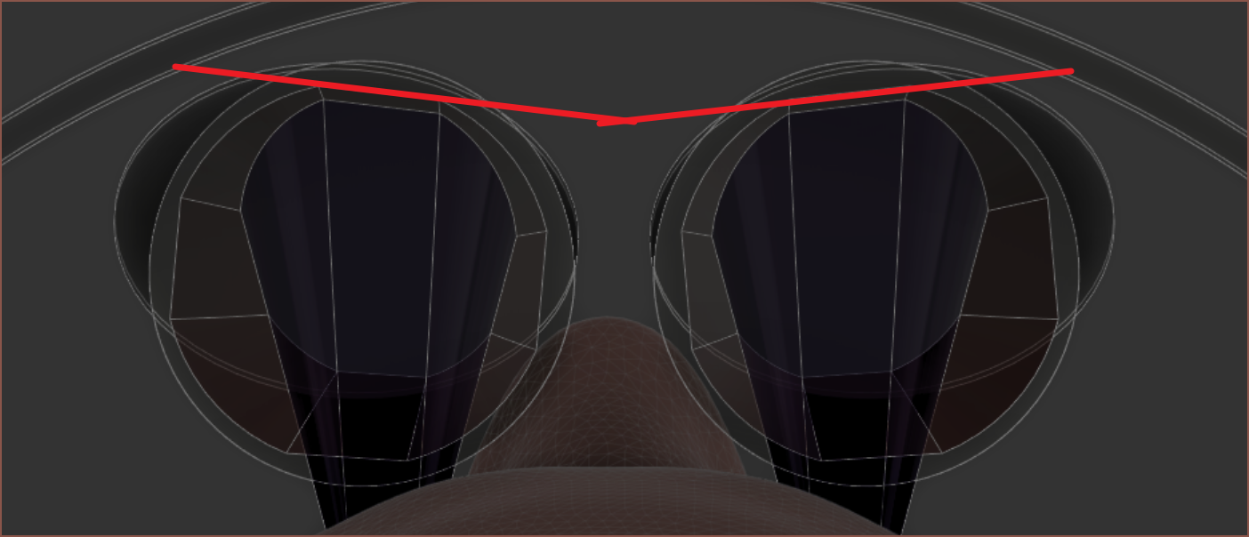
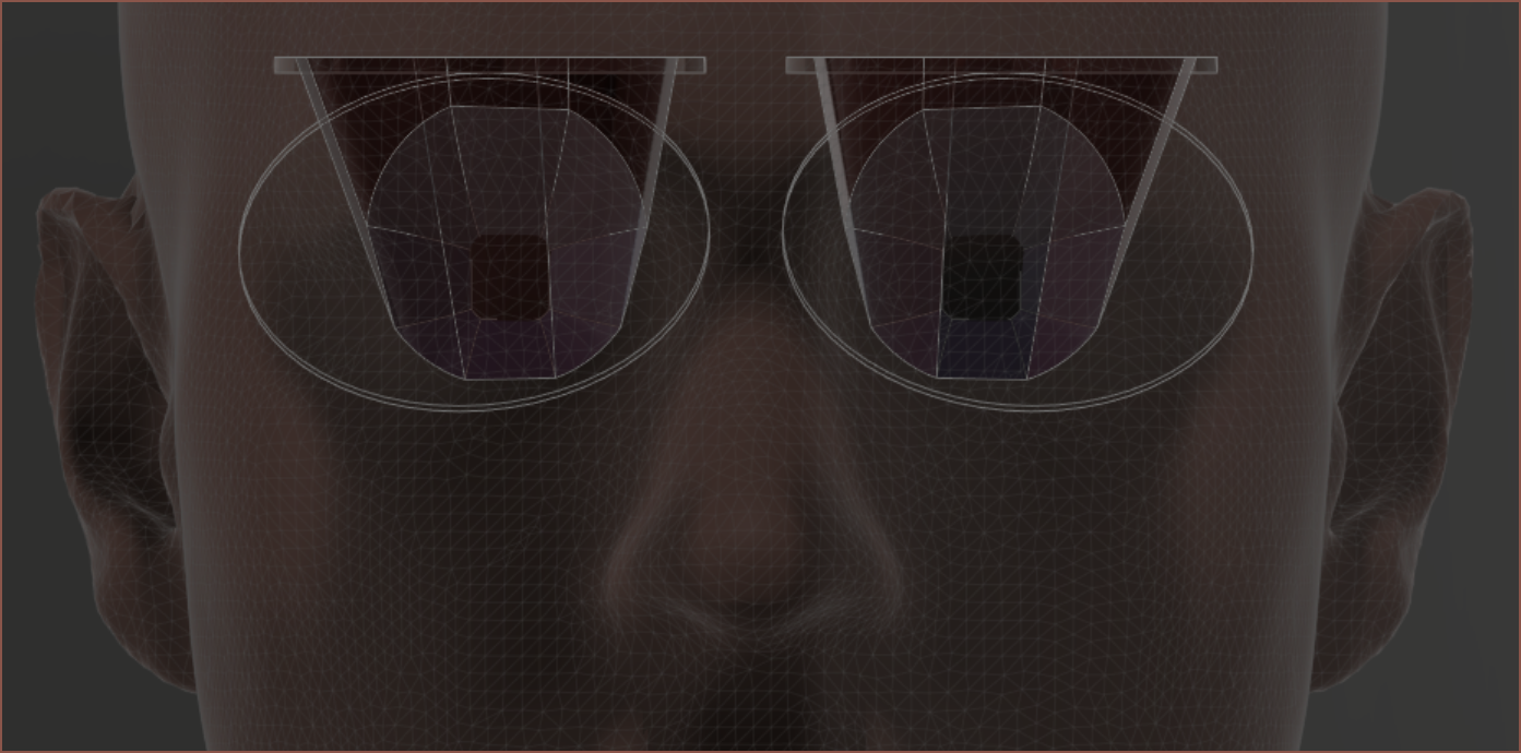
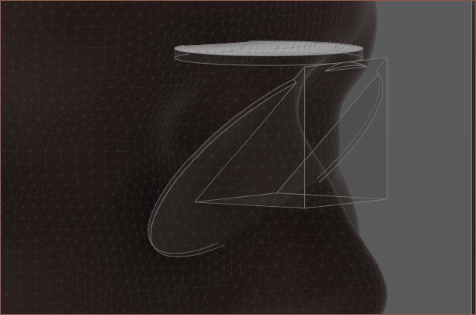
For 4:3 / 3:4 monitors and a 10mm eye box, I expect that the ray volume from the eye to the reflector combiner looks like this:
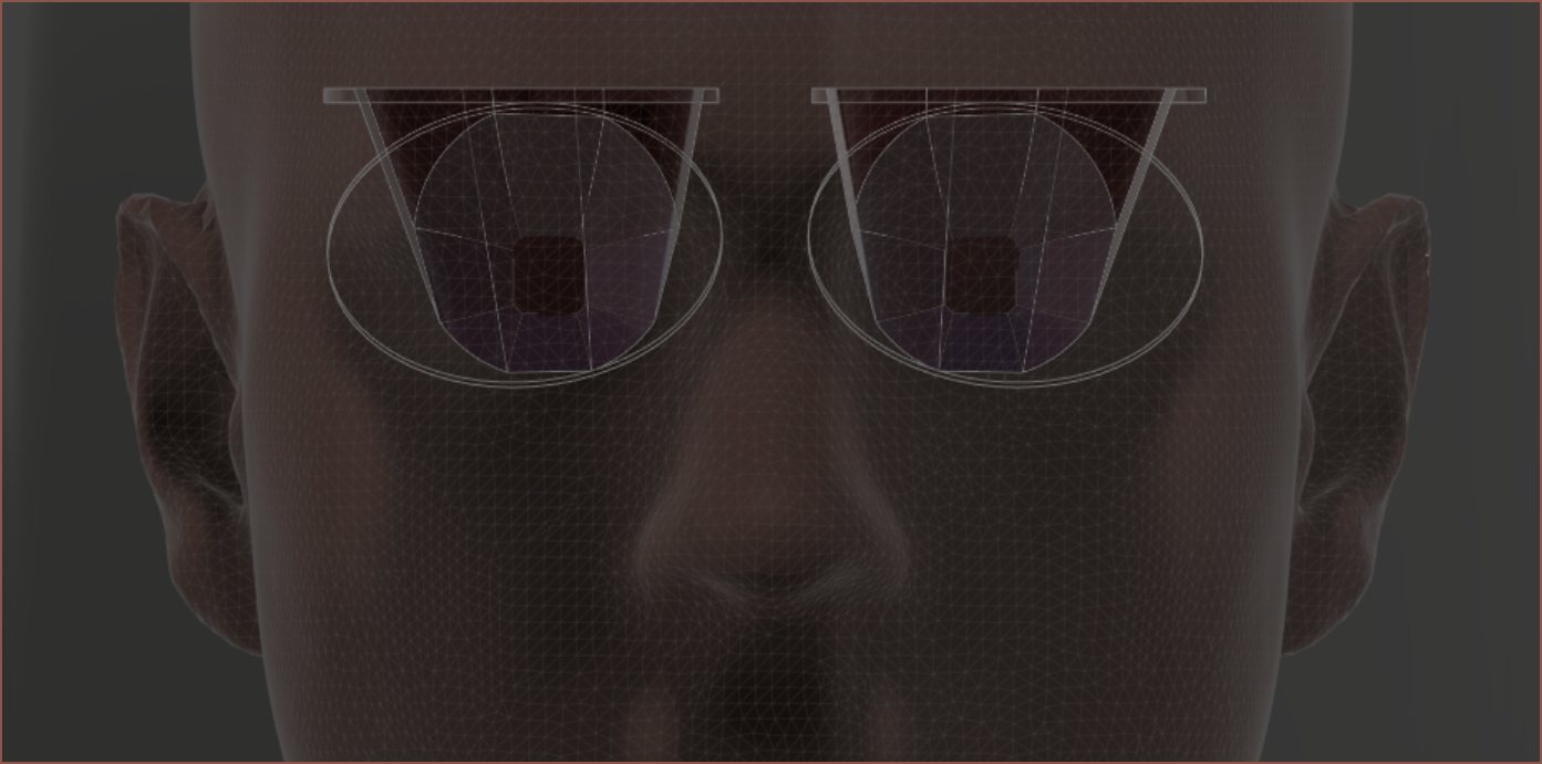
Unfortunately, geometry is often dissapointing and the rays conflict after the reflection:It also misses part of the lenses (highlighted in blue). I'll see what I can do after writing this log.
Lastly, I also wanted to mention that I want to add a 10x optical zoom camera and a thermal camera to TyMist if possible.
Finally got around to doing some optical simulation after thinking about what exactly the light is doing. For starters, I think it's easier to start from the eye and cast the rays backwards. That already made me realise that I actually want the image on the retina side of the eyeball lens. If the image is formed there, then you'd see it. Working backwards better allows me to see what rays -- friend or foe -- will hit the retina.
The reason why the image in the test rig looked tiny is because I was trying to grab the rays I'd see at >1m. I'd imagine that the image would look the same size if my eye was [insert system focal length] away too. I might be able to fix it just by bringing the fresnel lens in the decollimator closer.
Anyway, this is the simulation I set up to see if I could actually get a solution with the 30mm beamsplitter, and the short answer is "not really".
With these rays, I can finally understand why I was getting some mystery mirrored image on the bottom of my vision when I angled the right angled prism to reflect stuff 90 degrees off axis.
That bright section of rays is what I'd see through the F50 fresnel lens. The slightly darker section is the full 32 degrees I'm aiming for.
The length of the lens is the same as the length of the beamsplitter cube (or 30mm right angled prism)
Therefore, anything that misses the lens would've hit the front wall of the glass.
Due to the angle of light, these rays would've been totally internally reflected.
I've got the eye relief at 24mm and I can't have relected rays going past that point, so the beamsplitter reflective plane would have to move back. The rays in question would likely need a 40mm lens, thus a 40mm beamsplitter (or 45mm beamsplitter plane). I'm currently unsure as to if there's actually enough space infront of the head to acommodate that within the 300mm cylinder.
I'm not annoyed by the reflections... yet... but 25 degree FOV isn't exactly ideal. Every way I slice it, it feels small.
[17:00] You know those kinds of things that are simple and straightforward to do but don't do them because the idea of the process is kind of fuzzy? Yeah this test mount was like that.
It took only 40 minutes of modelling and it's going to take another 42 mins to print the beam condensing side of the test setup. I lost (or likely didn't even save) the optical ray tracing setup I did in November so I had to use the screen snips provided in those previous logs to set up the model.
Theoretically, what should happen is that I should be able to project an (IIRC) 9mm mirrored image of a screen at a wall and it will be the same size and sharpness at any distance.
Oh just noticed a mistake. Fixed:
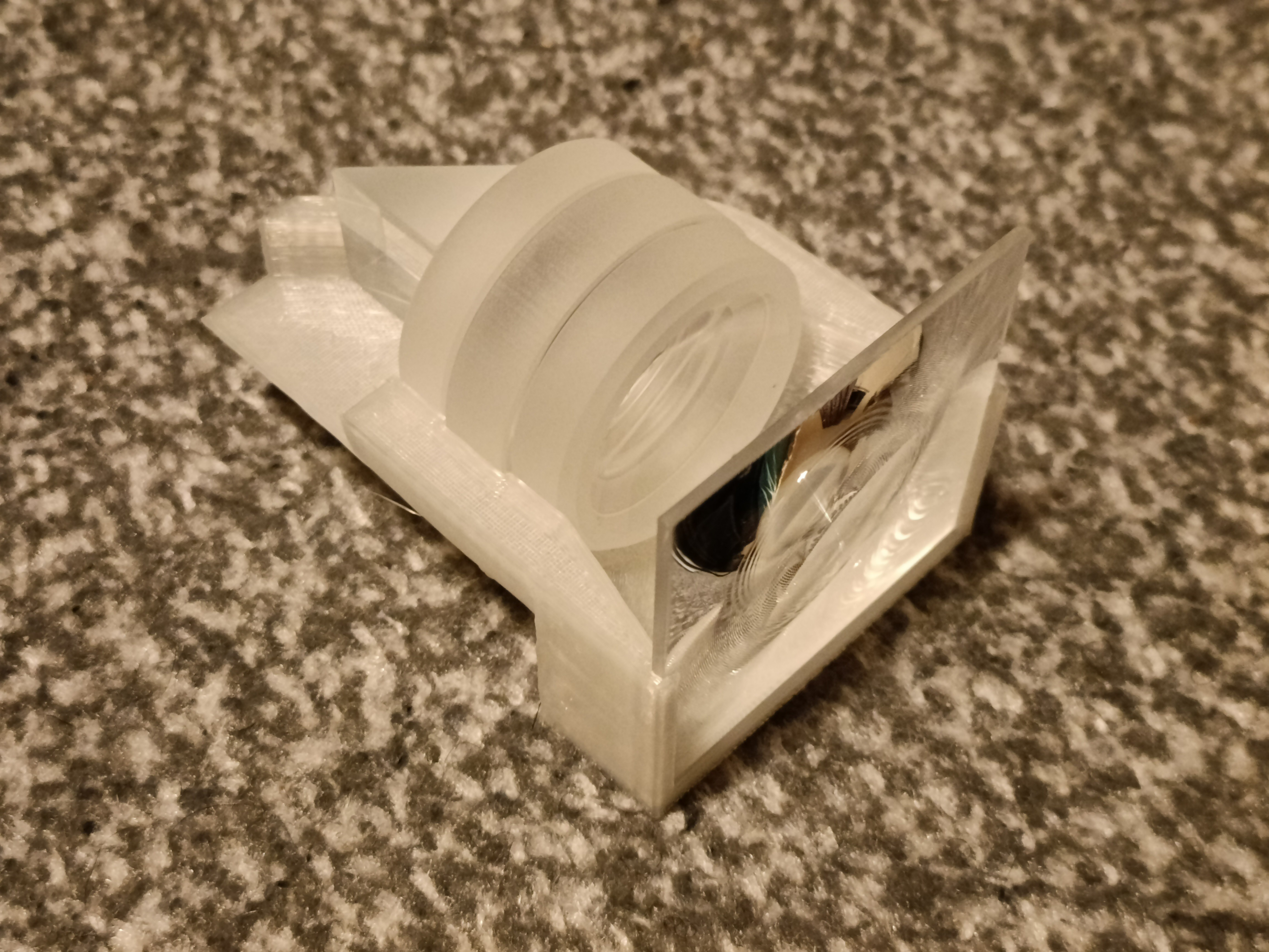
[19:00] So the print finished and the assembelled rig looks nice and exciting:
It looks really cool though the lenses (viewed where the 20mm prism is) but I didn't expect that all the visual area that wasn't the fresnel square would actually just be the walls of the other 3 lenses.
The middle of the image through the lens looks like it's at infinity but the sides of it doesn't. I think this is because I've dimensioned the space between the fresnel and the first lens from the closest side. This is not necessarily the same as the fresnel lens centre. For the decollimating optics, it should be correct, but for the above collimating optics, the dimension should've been on the outer side:
The red is the original way I dimensioned the lens and the blue is how it probably should've been dimensioned. That's the side where the fresnel ridges are, thus the optical "centre" of the lens. Right now, this means that my fresnel lens is mounted 2mm out.
The edges of the square are also rounded. I was kind of expecting this since these aren't aspheric lenses. I'm hoping that the decollimating optics balance it out.
It does seem that the image is more or less the same brightness as the screen. I'm not sure if that's just my brain doing relevant optical processing on it though, as it does look slightly brighter in the photo.
Looks really cool in there, even if I didn't intend for the lens rings to be visible.
This is the T.I.R. I was talking about in the previous log. I expect the beamsplitter to look somewhat similar. As said in a comment on that log, I'm going to try 30mm; I've printed the test cubes and placed them against my screen light protection (and very minor prescription) glasses, made a custom 2160x2160px resolution profile on my PC and moved in until the active area was in the bounds of the cubes. I put the distance into the calculator and I got 84.5PPD.
Oh right that's 2160px not 2880px. I was wondering why the FOV decreased.
[19:40] The print for the decombiner is done.
The issue is that the view from the fresnel is wrong. What I'm supposed to see is like a seriously zoomed up image, but it looks more like a door lens (a.k.a. even smaller!):Unlike the collimator, it does seem like decollimator is more sensitive to lens distances.
In the calculator, I've got 25mm but in the sim it's 22. Could it be to do with that? I doubt it because I can move the lens outside to get that 25mm distance and it just makes everything blurier. Also moving my eye off axis makes things blurrier.
Moving the F-30 lens closer makes the image smaller fast. I tried just holding the lenses and moving them but it's nothing but a difference between complete blur and kinda blurry.
[The Next Day (23 Jan), 00:38]
Ok I've got some good news. The fresnel for the collimator was actually really close to where it actually needs to be, accidentally. The image is inverted by about the same amount if the fresnel is outside its slot and pressed against the holder wall, which would be a displacement of 3.2mm. I've moved the mounting position +1.6mm of the original 27mm:
The difference from the simulation is likely caused by the fact that the glass lenses don't converge the light right in the middle of the lens. Instead, there are two concave faces, so the light will take a slightly different path.I've also found out that I've mounted the F-30 lenses backwards in it. They're supposed to be chamfered side pointing away from the fresnel lens. The image is slightly larger as a result.
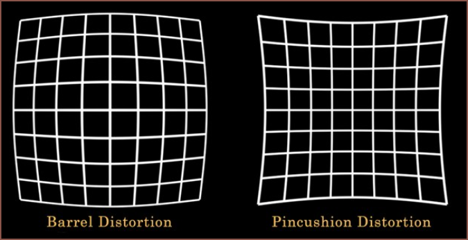
The bad news, as you may have already noticed, is that the resultant image is bent like a CRT monitor. That throws my image tiling strategy out of the window, even if the decollimator worked as intended. The official term is "barrel distortion" and if I had to pick one or the other, I'd go with this distortion.
Speaking of that decollimator, the 2 glass lenses just seem to make the image micro size. Trying to remember the virtual images of the simulation, I think that's supposed to happen so the simulation is seeming pretty accurate here. That means I've got to turn to the manufacturing.
I think the main issue is that spherical lenses are being used. Since even the edge of the fresnel lens is barrel-ified, I can only assume that it's the glassware doing this. That's a problem because it's not like I'm spoilt for choice in that department. Actually, now that I mention the distortion, it actually seems that the centre of the image at 27mm is at infinity but it's at 28.2mm where the edges of the image are approx infinity. I think fresnels are aspheric by default so maybe I can find some (or an AliExpress seller willing to make them).
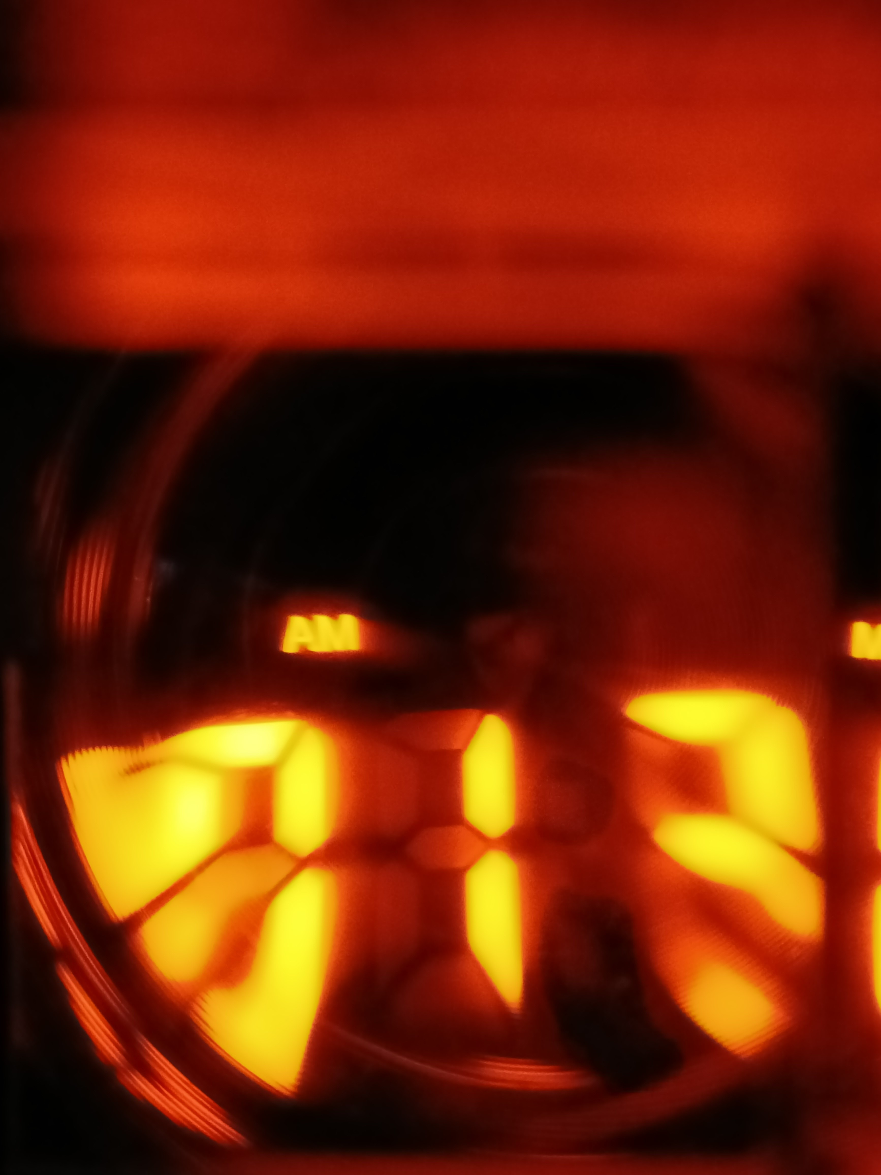
Actually, scratch that idea because I just tried looking through the two fresnels I've got like a telescope and it's a blurry mess. Now I understand what that yellow website was saying about not using fresnels for imaging purposes. Man that's like going from Unreal Engine 4 OLED to PSP 3000 graphics! Nah the PSP had better graphics than that... The PSP 3000 graphics with a wrip + torn screen protector over it. The super crisp and clear image from a single fresnel essentially turns into this... scratched up and old plasticy looking image when doubling up. You can kinda already see what I'm talking about by looking at the orange digits in the decollimator image above. Why am I writing a description? Just taking an image would be better:
Here's the image (which I've flipped so that "AM" is the right way up).
Anyway, this also makes it seem that if I'm going to use fresnel lenses, there can only be one in the image pipeline or else I'd never get 20:15 (80ppd) clarity. With such limitations, it's sounding even more like I'd be going with this new beamsplitter cube strategy so that the decombiner can be a traditional (but hopefully square) lens. If I use the large combiner solution, I'd be limited to just the 2560px screen due to its physical size.
[02:04] Print just finished and still the same issue of the centre of the image being at infinity but the sides are only near infinity.
The whole thing is supposed to be a single-colour blur like the centre, without the side lines.
The left is using a 35mm beamsplitter and the right is an older concept of the current proposed solution. The good news is that the 300mm design means that it looks (and would likely feel) much smaller; I didn't even notice that the helmet got taller until I compared it with an older render. It also looks more modern than the previous concept, yet still not as sleek (and dare I say edgy) as the single combiner concept.
Speaking of the single combiner, I don't think I'm going to be using 2-way mirror for this. Let me explain why.
These are the 2 devices I shortlisted for a not-so-temporary temporary TyMist (similar to the i3 Amoled being my not-so-temporary temporary wearable whilst mining for #Tetent TimerSpy [gd0136]) but there were 2 things that just failed the solution: FOV and blackness. Notice how I didn't say resolution. The HUAWEI uses 1600^2px screens and the Royole is 1080p; it's not ideal but it is servicable. The issue is that the pixels are spread over a uselessly massive area, and even if it was reduced, there'd be complete darkness around the screen. I can't tolerate that for regular screens even when watching videos, much less doing any work.
This made me realise that I don't just need to see the outside world, but that there has to be a good amount of light coming in too.
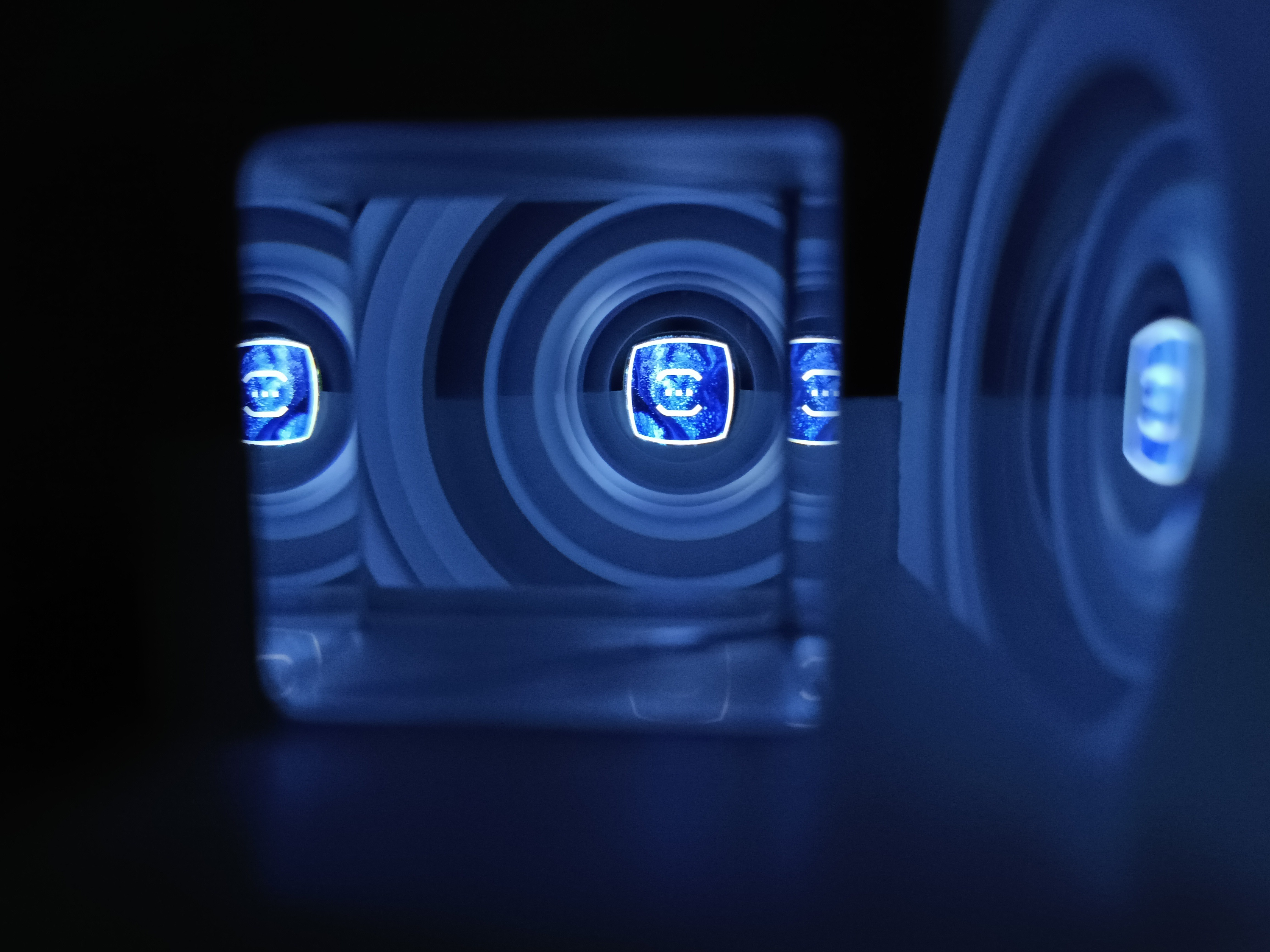
I've printed some 40mm "cubes" that should give a geometric and visual indication of looking thought the beamsplitter. Due to the shallow angles between the faces I've printed on the actual beamsplitter cube, those faces would reflect light and not allow light to just pass through.
It's... okay. 40mm is slightly too big, but the PPD calculator says that I won't be able to do a 30mm cube with a 25mm eye relief at 90PPD. I could do 97.5PPD though, barely. 35mm sounds like the nice middle ground. The "optical bezels" are also quite large (like 30% of the width of the see-though area), but because they're a medium-light grey instead of black, it's not so bad actually.
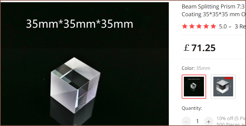
I think this cube is more expensive than usual because it's a 7:3 and not a 5:5.It also seems that the left+right faces of the cube (that have that diagonal line on it) are frosted to prevent such reflections.
Speaking about the price, it sure increases fast after 25mm^3. I coudn't specifically find a 5:5 35mm^3 but there are 40mm ones where the listings usually say that the cube can be customised and those ones are £50. Now that's a lot of £££, but I'm struggling to compute a solution using the much cheaper but quite thin beamsplitting panes since they seem harder to mount in the 300mm cylinder and I imagine it visualy looks worse from both the first and third person perspective.
The 300mm helmet visibly looks nicer to move in, but the real bargaining chip it has is that I can buy a 300mm acrylic tube section but I can't get a 350mm one.
Today, I've been thinking, computing to see if there's a solution that uses beamsplitter cubes, prisms and total internal reflection to pipe the image instead of a large combiner. I got this idea from seeing the range of Epson AR glasses.
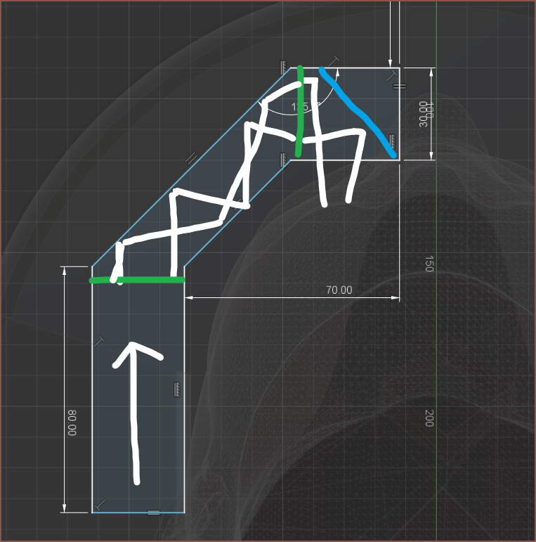
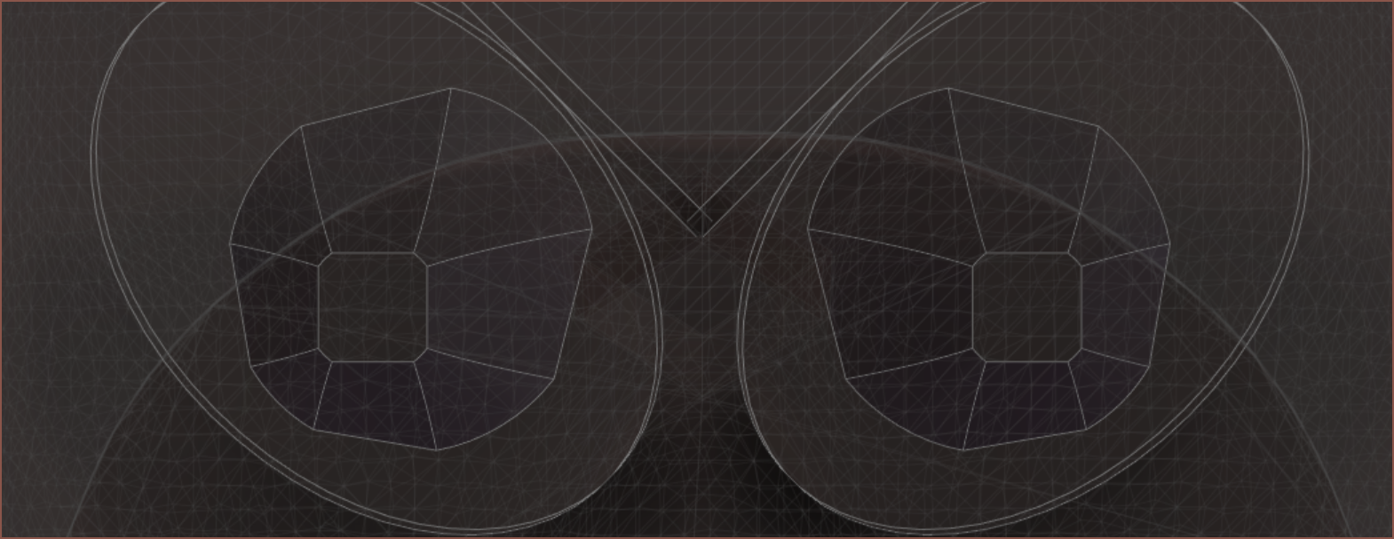
For the potential comlpexitiy, I currently can only imagine it being an option to reject the 350mm cylinder solution. 300mm is a more ideal size than 350mm as it's visibly slimmer and air stream closer to the nose. Alternatively, another solution altogether might exist that doesn't use a somewhat expensive (£60 - 83) acrylic tube door.It certainly looks geekeir though. There's also the issue of being able to hold all the parts together. A lens of some description will have to exist right after the beamsplitter cube to redirect the Field Of View light paths so that they don't hit the walls of the glass. In the below image, the white is the FOV cone and the green lines are lenses. The blue line is the beamsplitter reflection. It's possible that I could make the beams parallel up until the lens closest to the beamsplitter, meaning that the one closest to the white arrow could be omitted.
 kelvinA
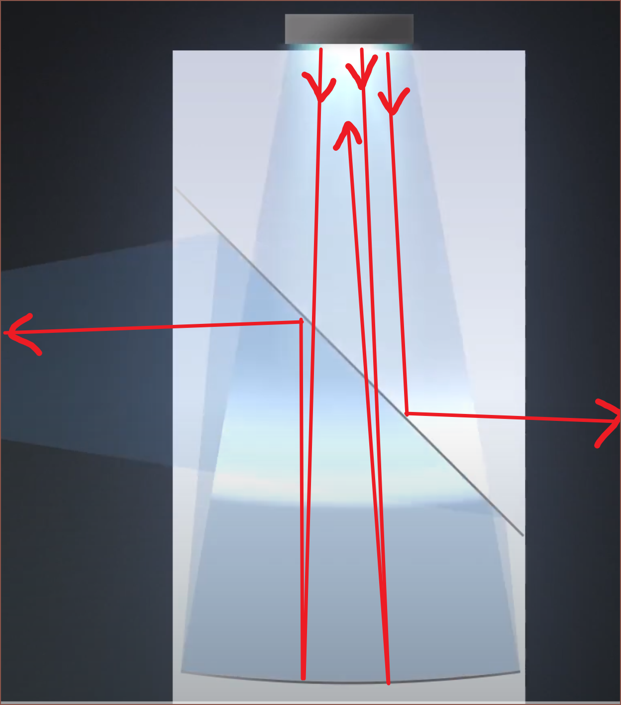 Since the whole system is reflective, there's no opportunity chromatic abberations either.
 But that sounds like having to print stainless steel and glass (or some high temp transparent material due to the sintering of stainless steel) in the same print, along with polishing gear in the Brick of Innovation to get this kind of finish:
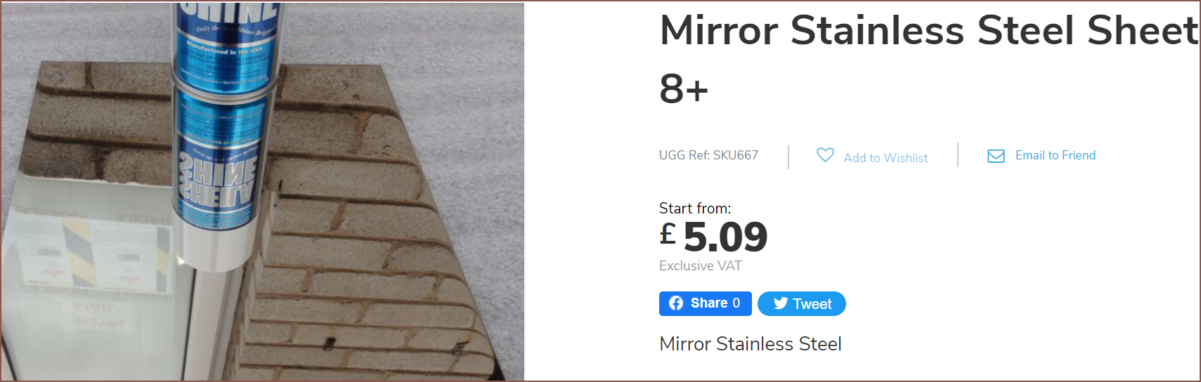
 I've hopefully got a new solution for the optical pathway, and I should have a better understanding of how things should work out.
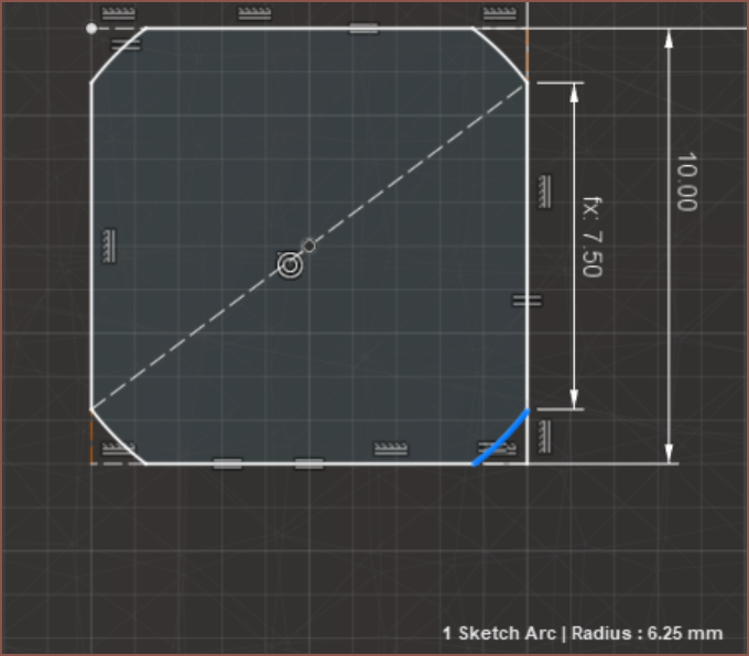
 It actually looks... kinda smart looking. I haven't modelled it in, but just imagine there's 2 curved sticks maybe 5-10mm in diameter on the edges of the optics to hold them:
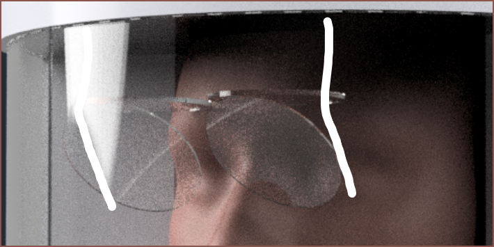
 It's likely I'd get a bit of visual blur on the edges of the combiner, so 60mm is likely the visually better choice.
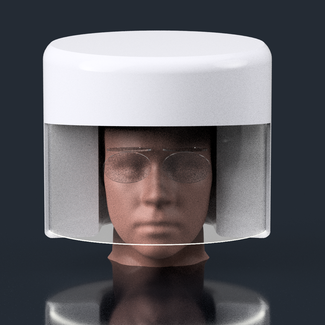 This oval visually looks more tame from the 3rd person perspective too. It looks more like a cleanroom lab guy than a disco kid.
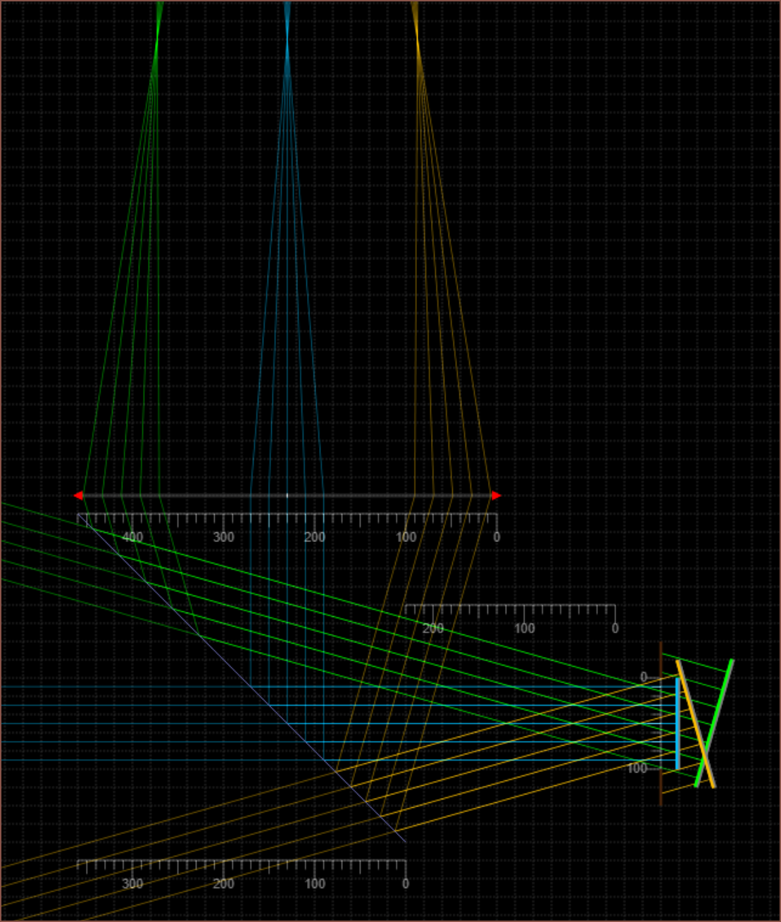 So, by enabling "simulate colours" and aligning 2 "beam"s to have the same angle as +/- 16 degree (and blocking out the excess), I was able to get rays that look like the optical rays diagrams I've been seeing in AR diagrams such as this one I've recently seen:
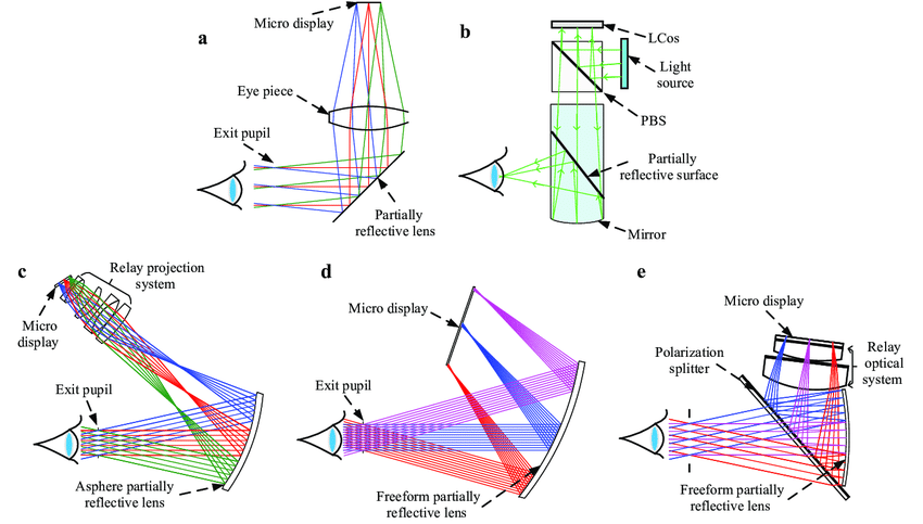
 The white line is where the eye starts. I'm going for a 10mm eyebox (the scale in these simulations is 10 units : 1mm) and the lines pointed to by the arrows is the cone of light I care about.
 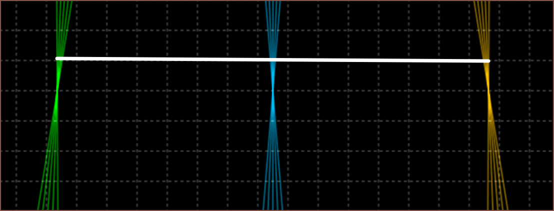 I think that the focus point is juuuuust behind (or infront) of the locationwhere the rays merge together into a point. This is because the pixel isn't an infinitely small point. The rays are also used to see the distance and size of the screen when focused at infinity. This is a notable difference to where I thought this location would be. Let me add a red beam to show you what I was doing before:
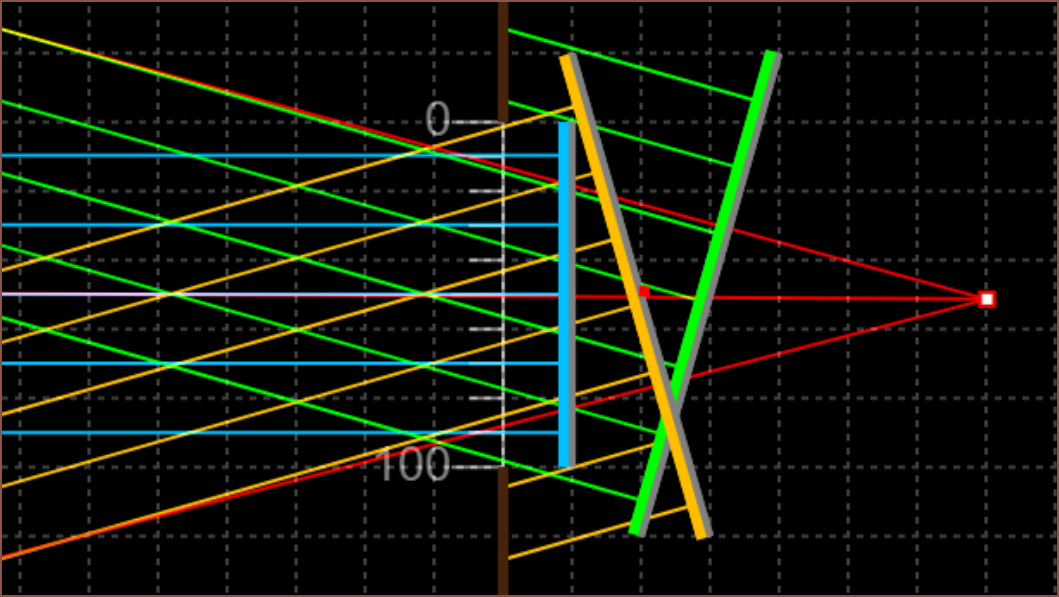
 The lime green line is a screen with the right focus but wrong size, and the red line is the 18mm 2560px display size. Looking at where the actual FOV lines are, I would've misplaced this even further back. So, technically, the screen at the red location would've taken up my entire view, but that would've only been with 1 out of the 5 rays. The other 4 rays, likely originating from a black wall or something that isn't the screens active area, would make the edges mostly wall. At the same time, the centre is getting light from a wide part of the screen, so all those rays would get blended too. What would this look like? A stereotypical blurry blob of light that blur-fades into darkness the closer to the edges I look.
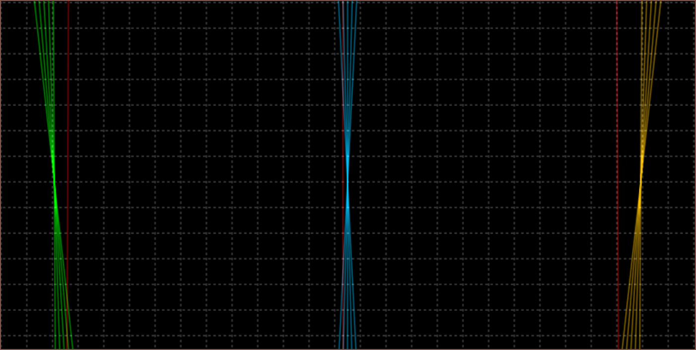 Well I've got some lenses so I might as well see if my hypotheses are correct or not. The below is F-30 and indeed if I look though the lens I actually have with my eye set to infinity, it just looks like a blur at any distance:
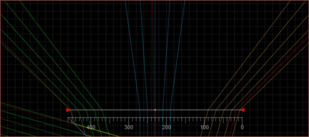
 Allegedly, if my eye is 60mm away from the lens and the image source is 40mm behind it, I should be able to see it at focus=infinity.
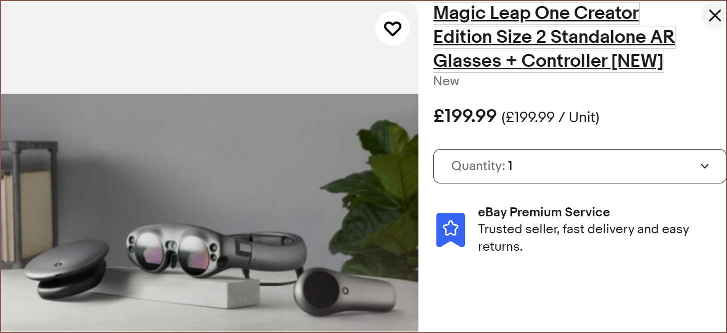 To be honest, the price anchor of £2000+ MSRP wore off after about 5 minutes, and the single reason is due to the low resolution. If I'd never heard of Magic Leap or this was some AliExpress manufacturer, I'd be like "expectable price". I mean, it also includes the computing power too so that's why it's still in my mind.
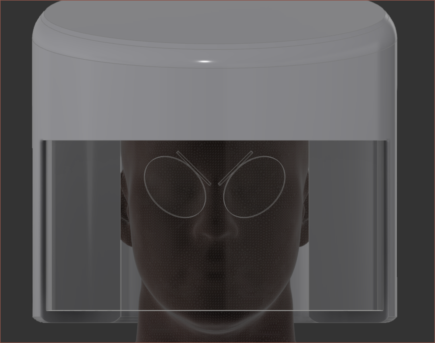
 First create the beamsplitter and fresnel lens. The lens here is 40mm so maybe it's possible to find a non-fresnel alternative for higher image quality.
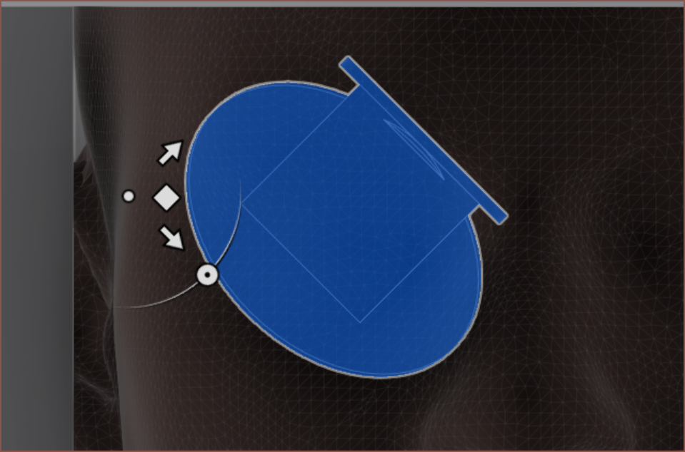 Next rotate the front face 45 degrees and move the assembly forward until the lens misses the forehead:
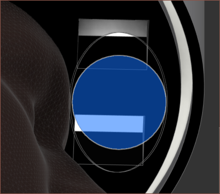
 Unfortunately, geometry is often dissapointing and the rays conflict after the reflection:
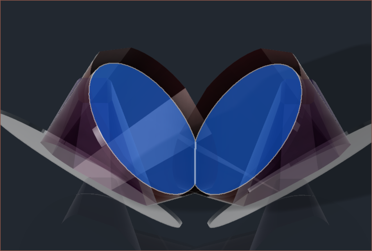 It also misses part of the lenses (highlighted in blue). I'll see what I can do after writing this log.
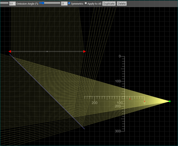 With these rays, I can finally understand why I was getting some mystery mirrored image on the bottom of my vision when I angled the right angled prism to reflect stuff 90 degrees off axis.
 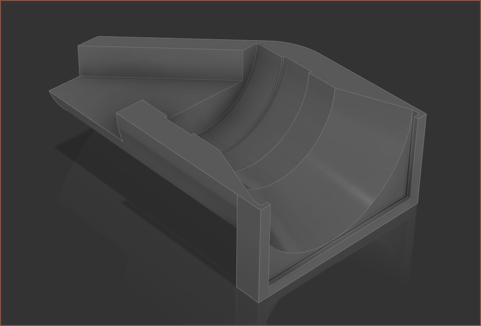 It took only 40 minutes of modelling and it's going to take another 42 mins to print the beam condensing side of the test setup. I lost (or likely didn't even save) the optical ray tracing setup I did in November so I had to use the screen snips provided in those previous logs to set up the model.
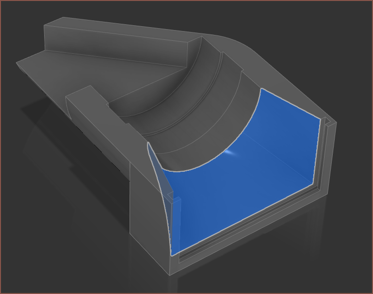
 It looks really cool though the lenses (viewed where the 20mm prism is) but I didn't expect that all the visual area that wasn't the fresnel square would actually just be the walls of the other 3 lenses.
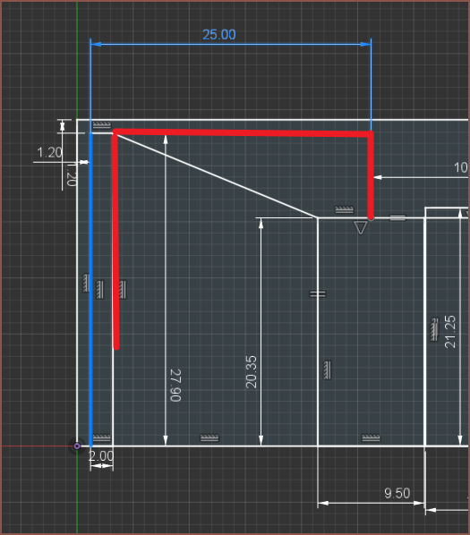
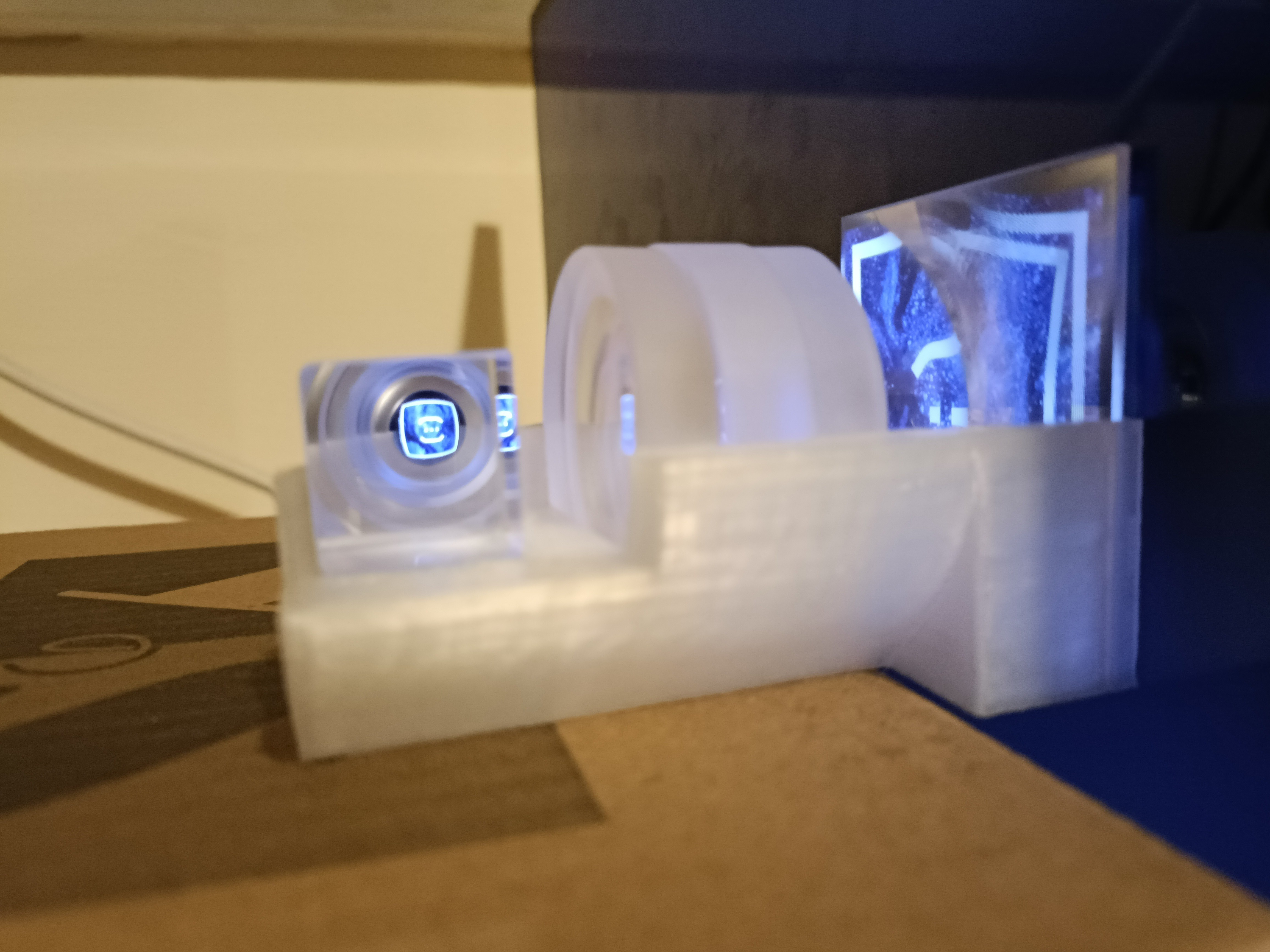
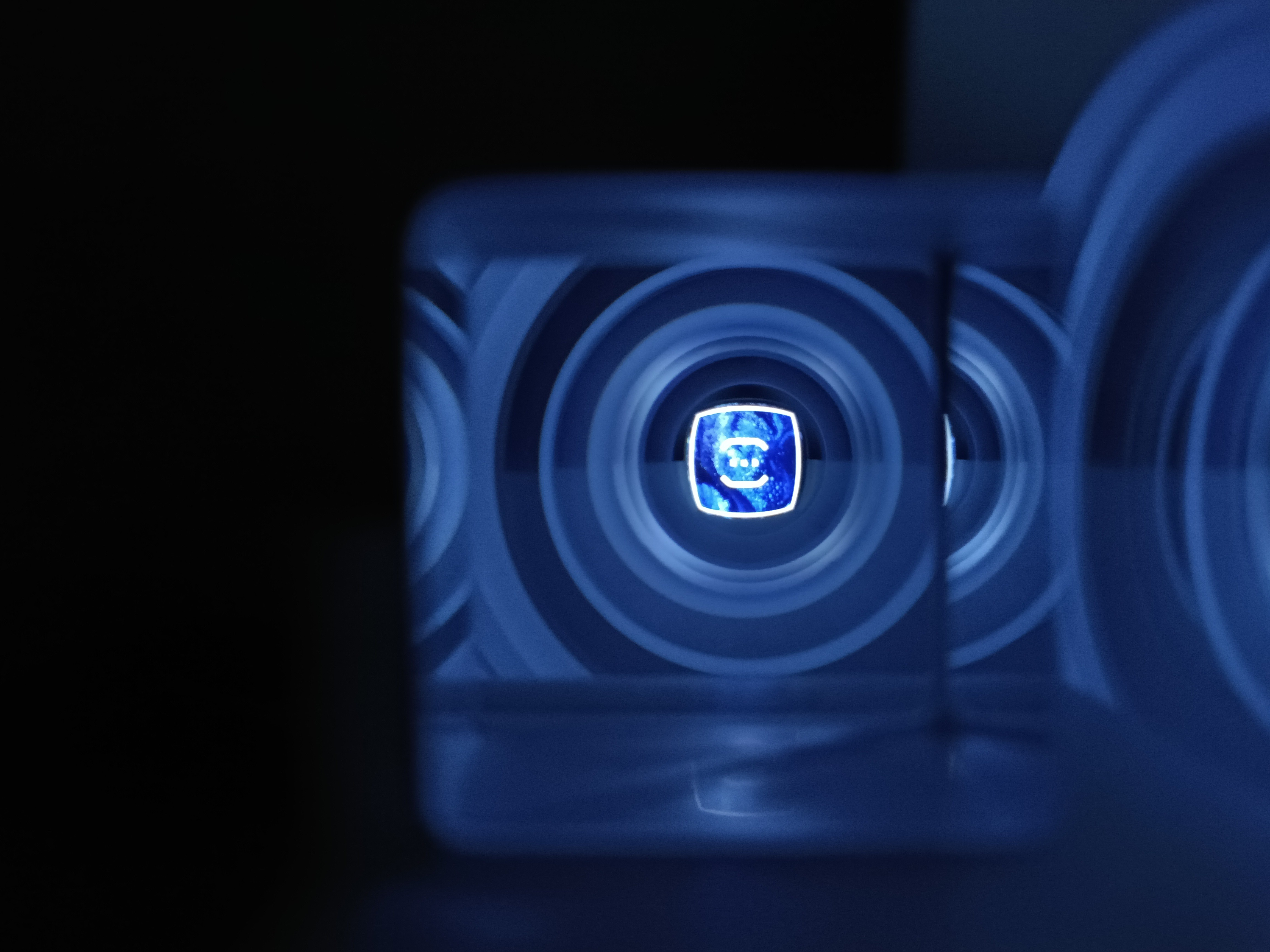
 This is the T.I.R. I was talking about in the previous log. I expect the beamsplitter to look somewhat similar. As said in a comment on that log, I'm going to try 30mm; I've printed the test cubes and placed them against my screen light protection (and very minor prescription) glasses, made a custom 2160x2160px resolution profile on my PC and moved in until the active area was in the bounds of the cubes. I put the distance into the calculator and I got 84.5PPD.
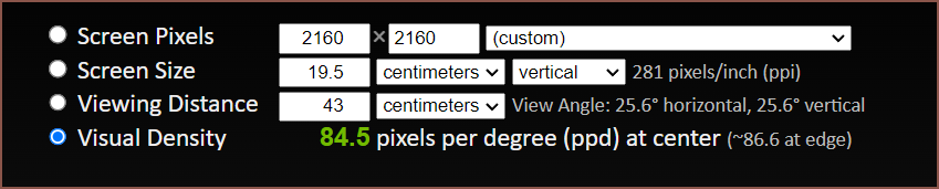 Oh right that's 2160px not 2880px. I was wondering why the FOV decreased.
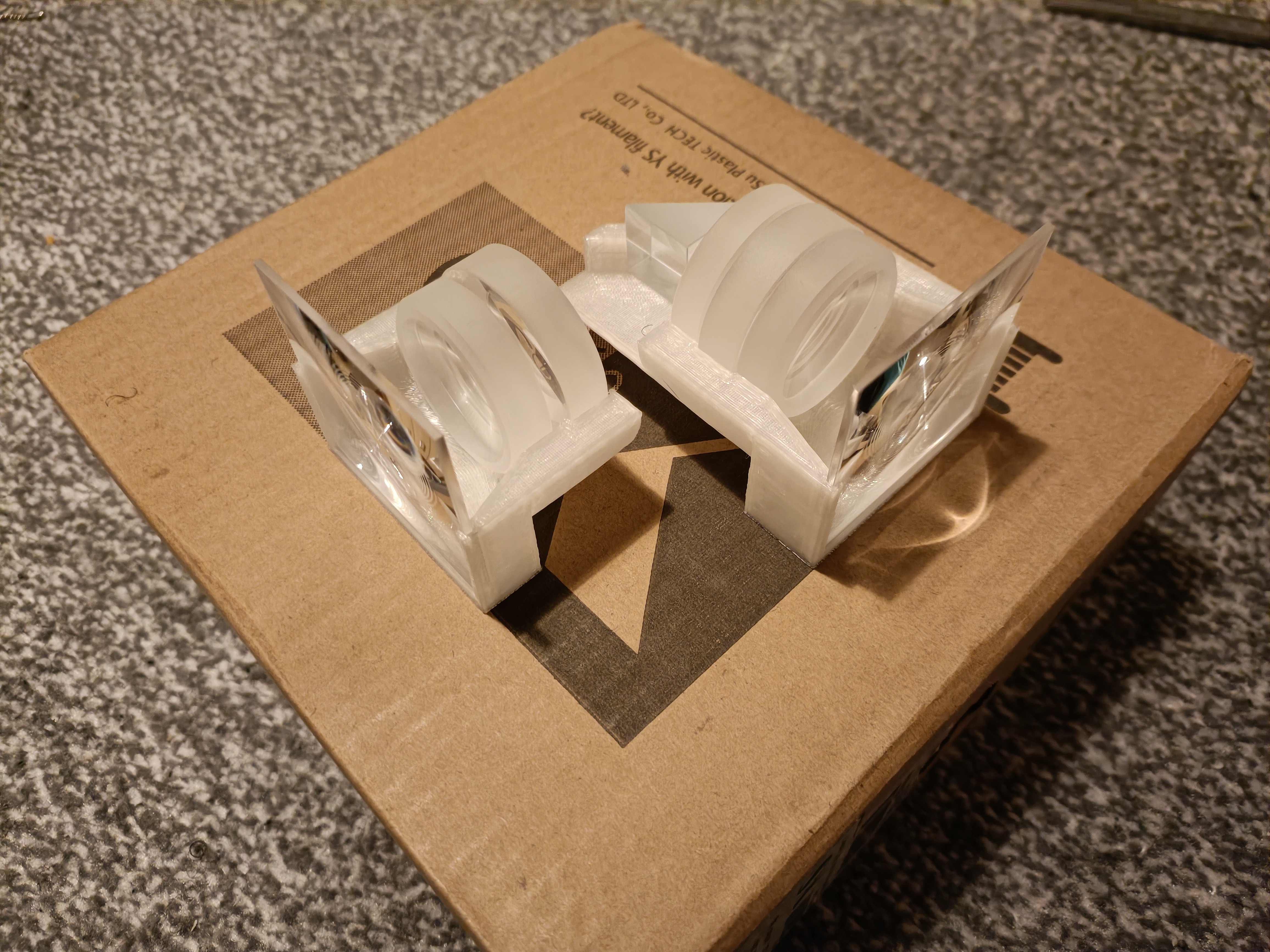 The issue is that the view from the fresnel is wrong. What I'm supposed to see is like a seriously zoomed up image, but it looks more like a door lens (a.k.a. even smaller!):
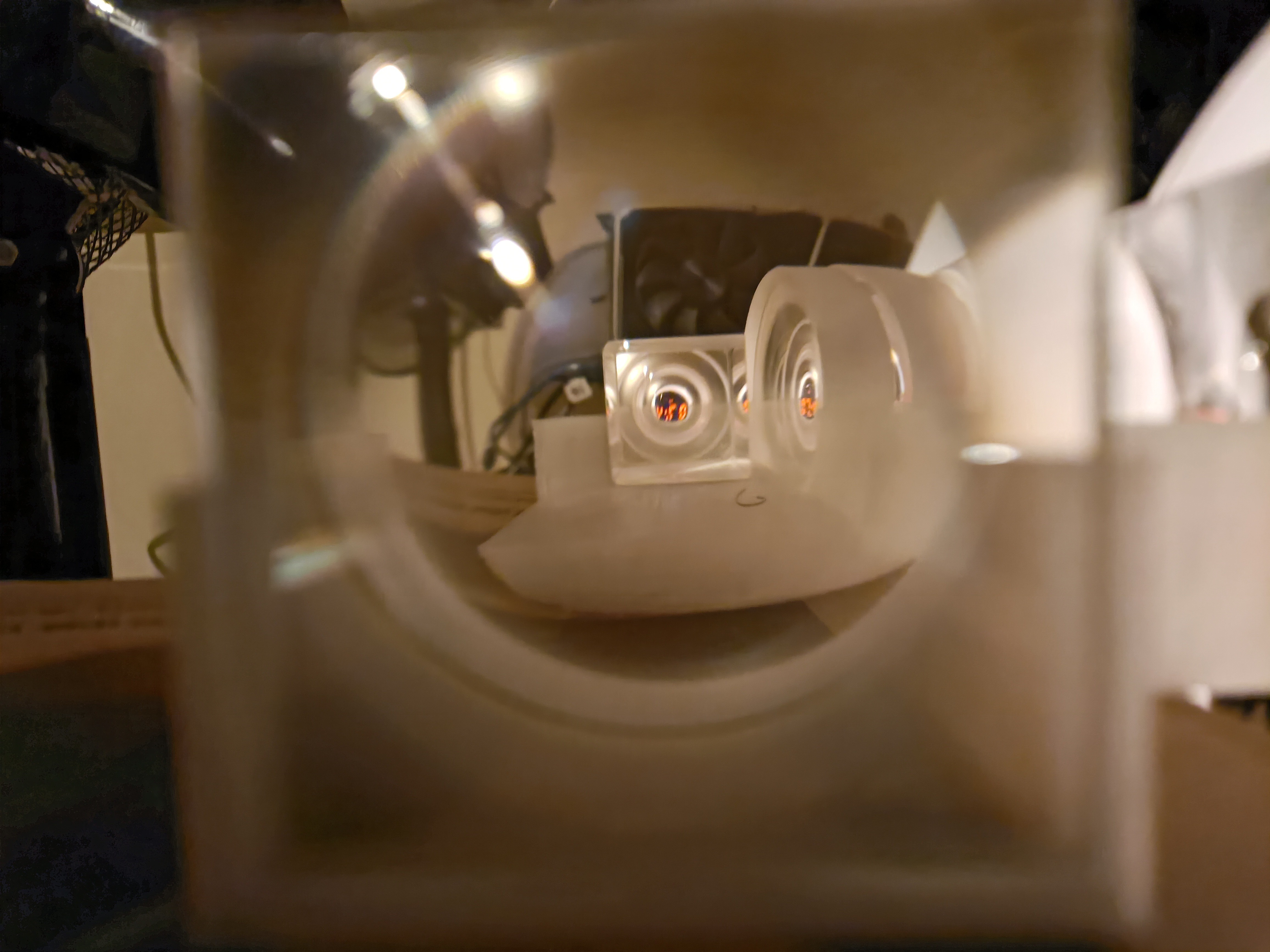 Unlike the collimator, it does seem like decollimator is more sensitive to lens distances.
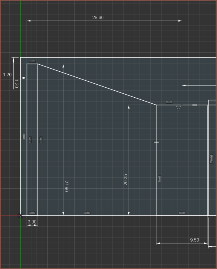
 Here's the image (which I've flipped so that "AM" is the right way up).
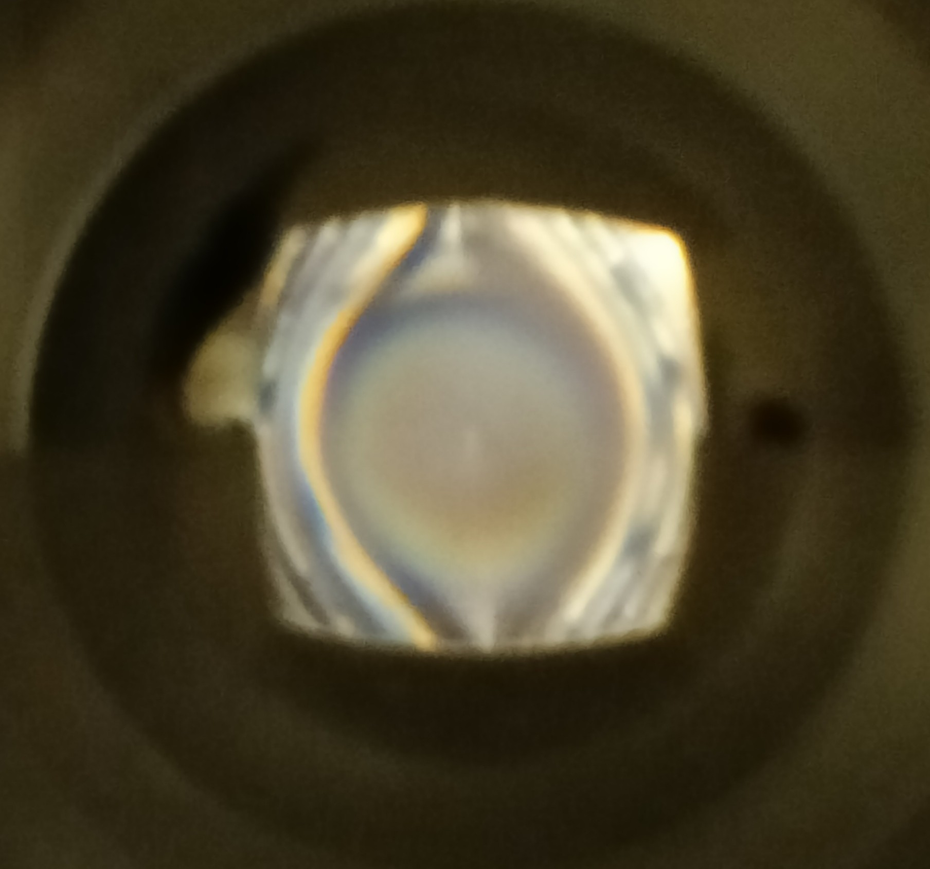 The whole thing is supposed to be a single-colour blur like the centre, without the side lines.
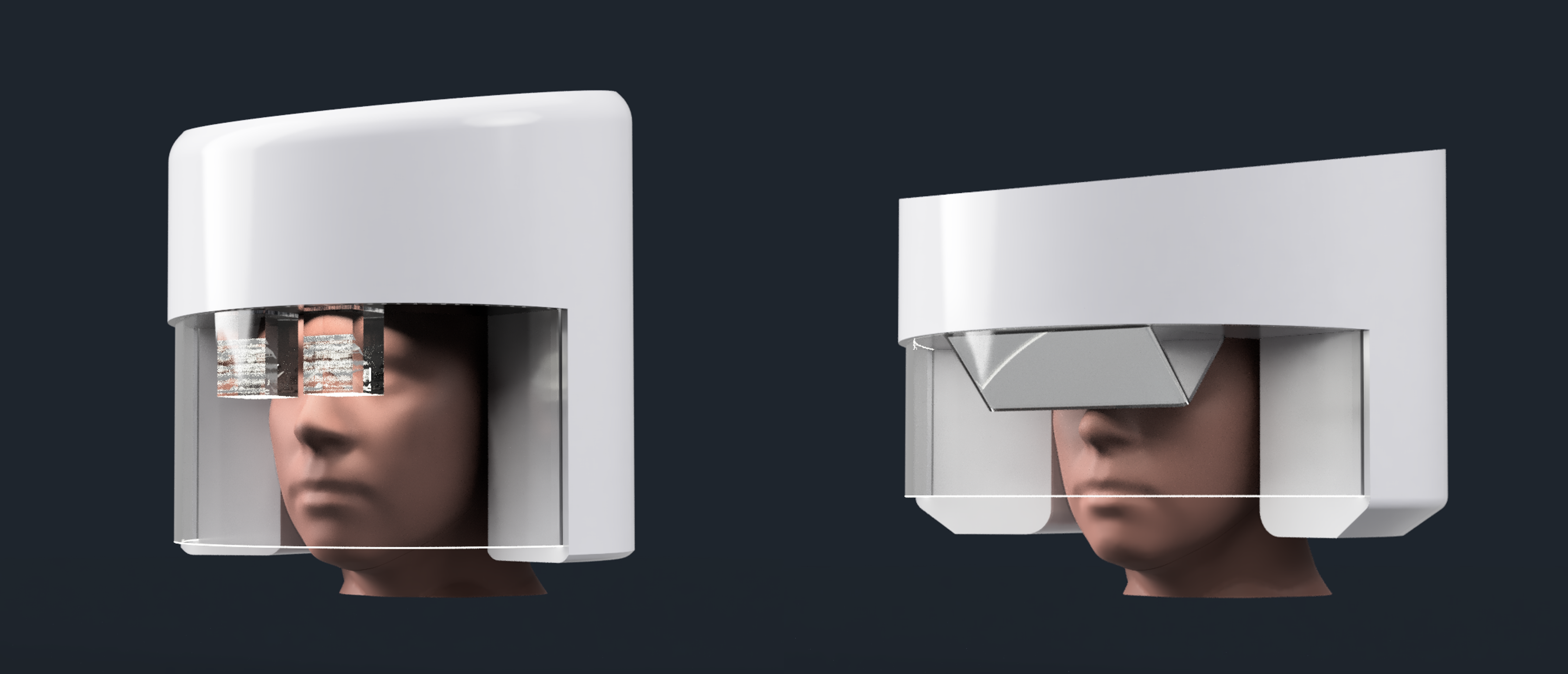 The left is using a 35mm beamsplitter and the right is an older concept of the current proposed solution. The good news is that the 300mm design means that it looks (and would likely feel) much smaller; I didn't even notice that the helmet got taller until I compared it with an older render. It also looks more modern than the previous concept, yet still not as sleek (and dare I say edgy) as the single combiner concept.
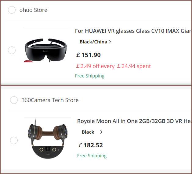 These are the 2 devices I shortlisted for a not-so-temporary temporary TyMist (similar to the i3 Amoled being my not-so-temporary temporary wearable whilst mining for
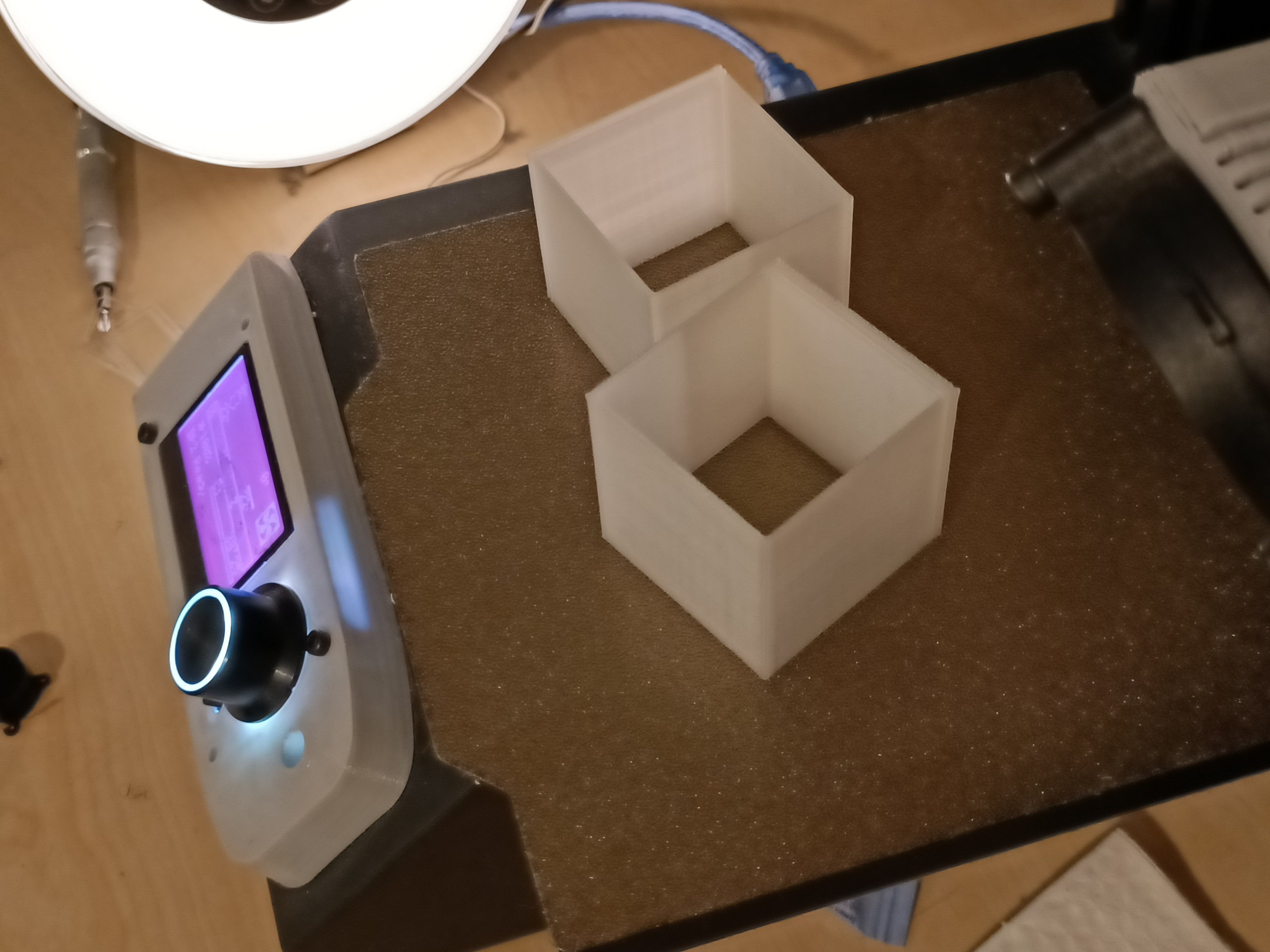
 Today, I've been thinking, computing to see if there's a solution that uses beamsplitter cubes, prisms and total internal reflection to pipe the image instead of a large combiner. I got this idea from seeing the range of Epson AR glasses.
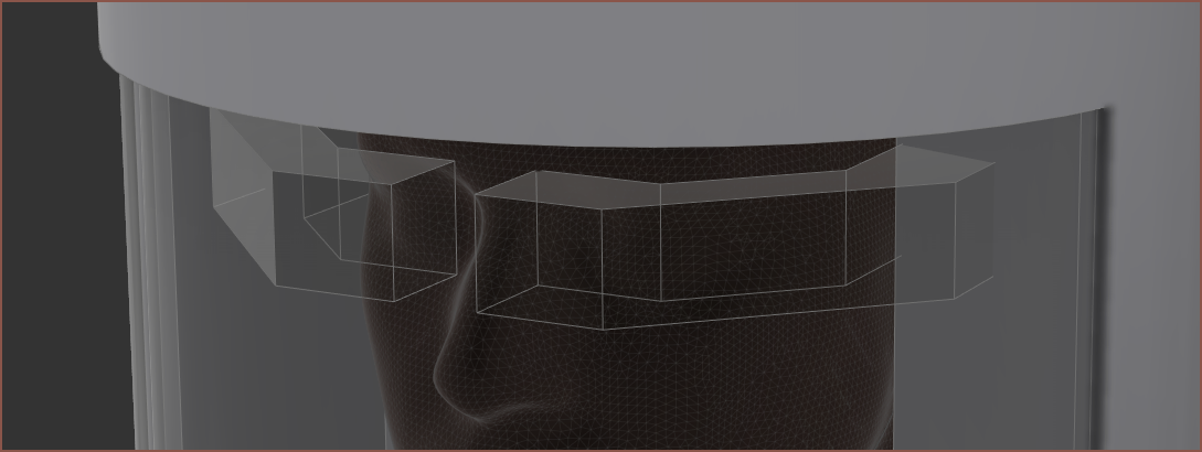 It certainly looks geekeir though. There's also the issue of being able to hold all the parts together. A lens of some description will have to exist right after the beamsplitter cube to redirect the Field Of View light paths so that they don't hit the walls of the glass. In the below image, the white is the FOV cone and the green lines are lenses. The blue line is the beamsplitter reflection. It's possible that I could make the beams parallel up until the lens closest to the beamsplitter, meaning that the one closest to the white arrow could be omitted.