 Cyrille Gindreau
Creating the hackaday logo with a MSP430 and a laser.
Project files can be found here:
Draw the hackaday logo with a laser with less than 1K of data.
Already have an account? Log in.
To make the experience fit your profile, pick a username and tell us what interests you.
Creating the hackaday logo with a MSP430 and a laser.
Project files can be found here:
At this point, we decided to abandon the concept of mirroring. If we had had a much more complex design with many more points and more than 1kb, mirroring would have saved us space. Due to having so little space however, the algorithms power wasn't able to give us the results we were looking for.
We had by this point made so many optimizations to our code that when we reverted to a single array, the total size was 902 bytes! The final program:
#include <msp430.h>

#define uint8_t unsigned char
#define uint16_t unsigned int

#define LASER BIT0
#define SSOUT P1OUT
#define SSX BIT6
#define SSY BIT7

#define length 234

void writeMCP492x(uint16_t data,uint8_t ss);
void drawLine(uint16_t, uint16_t, uint16_t, uint16_t);

int main(void) {
     WDTCTL = WDTPW | WDTHOLD;	// Stop watchdog timer
     PM5CTL0 &= ~LOCKLPM5;//reset fram

     CSCTL1 |= DCORSEL_6;//sets clock speed (16mz)

     P1DIR |= BIT0 + SSX + SSY;//p1 output
     P1OUT |= BIT0;//set bit 0

     ///////////////
     ///SPI Int//////
     ////////////////
     P5SEL0 |= BIT1 + BIT2;
     UCB0CTLW0 |= UCSWRST;                     // **Put state machine in reset**
     UCB0CTLW0 |= UCMST+UCSYNC+UCCKPL+UCMSB;   // 3-pin, 8-bit SPI master MSB
     UCB0CTLW0 |= UCSSEL_2;                    // SMCLK
     UCB0BR0 |= 0x01;						  // CLK / 1
     UCB0BR1 = 0;
     UCB0CTL1 &= ~UCSWRST;

     //The coordinates for the laser to traverse. Even index are X values, odd index are Y values.
     uint8_t logo[] = {66, 158, 47, 177, 37, 176, 27, 177, 16, 186, 8, 195, 8, 212, 27, 195, 47, 220, 27, 236, 40, 238, 56, 233, 66, 220, 68, 212, 68, 203, 86, 186, 75, 175, 66, 158, //lower left wrench:36
         	66, 98, 47, 79, 37, 80, 27, 79, 16, 70, 8, 61, 8, 44, 27, 61, 47, 36, 27, 20, 40, 18, 56, 23, 66, 36, 68, 44, 68, 53, 86, 70, 75, 81, 66, 98, //upper left wrench:36
     		118, 125, 110, 136, 102, 138, 86, 120, 95, 105, 97, 108, 102, 114, 110, 118, 118, 125, //left eye:18
			190, 158, 209, 177, 219, 176, 229, 177, 240, 186, 248, 195, 248, 212, 229, 195, 209, 220, 229, 236, 216, 238, 200, 233, 190, 220, 188, 212, 188, 203, 170, 186, 181, 175, 190, 158,//lower right wrench:36
			190, 98, 209, 79, 219, 80, 229, 79, 240, 70, 248, 61, 248, 44, 229, 61, 209, 36, 229, 20, 216, 18, 200, 23, 190, 36, 188, 44, 188, 53, 170, 70, 181, 81, 190, 98, //upper right wrench:36
			138, 125, 146, 136, 154, 138, 170, 120, 161, 105, 159, 108, 154, 114, 146, 118, 138, 125,//right eye: 18
			80, 159, 127, 180, 175, 159, 187, 120, 175, 84, 162, 70, 155, 55, 146, 55, 140, 70, 137, 70, 131, 55, 121, 55, 117, 70, 115, 70, 108, 55, 98, 55, 93, 74, 80, 84, 67, 120, 80, 159,//face: 40
			127, 103, 130, 91, 133, 83, 127, 91, 121, 83, 125, 91, 127, 103//nose:14
     };
     //keeps track of where in the array we are.
     uint8_t myIndex = 0;
     //used for creating delays due to the difference in speed between processing and moving a mirror.
     uint16_t counter;
     /*
      * main program loop. Iterates logo array two at a time and calls drawline function
      * with either the next four array points or the next two from the index and the
      * beginning two entries creating a loop.
      * Also checks if the laser should be turned off while traversing between
      * two points.
     */
     while(1){
    	 if(myIndex < length-3){
    	 	//Check if laser should be turned off.
    	 	if(myIndex == 34 || myIndex == 70 || myIndex == 88 || myIndex == 124 || myIndex ==160 || myIndex == 178 || myIndex == 218 || myIndex == 232){
    	 	 	for(counter = 1200; counter > 0; counter--){
    	 	 		counter = counter- 1;
    	 	 	}
    	 	 	P1OUT &= ~LASER;
    	 	 }
    	 	 //Draw a line from X,Y to X', Y'
    	 	 drawLine(logo[myIndex], logo[myIndex+1], logo[myIndex+2], logo[myIndex+3]);
    	 	 //Check if laser should be turned back on.
    	 	 if(myIndex == 34 || myIndex == 70 || myIndex == 88 || myIndex == 124 || myIndex ==160 || myIndex == 178 || myIndex == 218 || myIndex == 232){
    	 	    	for(counter = 800; counter > 0; counter--){
    	 	    		counter = counter- 1;
    	 	    	}
    	 	        P1OUT |= LASER;
    	 	 }
    	 	 myIndex = myIndex +2;
    	 //Loop back to beginning of array.
    	 } else {
    	 	 for(counter = 1200; counter > 0; counter--){
 	 	 counter...
Read more »
We were close, about 200 bytes away, it was time to get creative. The first thing we did was to flip our coordinates so that we were right side up. Second, we added the coordinates for where the laser should turn off (which actually brought our size count up to about 1500 bytes). Then we started experimenting a little bit. We broke up the logo into different sections: A wrench, the skull, one eye and the nose. The idea was that we could mirror the different pieces to save space. Our first take on the mirroring algorithm:
//lower left wrench
uint16_t wrench[] = {265, 635, 190, 710, 150, 705, 110, 710, 65, 745, 35, 780, 35, 850, 110, 780, 190, 880, 110, 945, 160, 955, 225, 935, 265, 880, 275, 850, 275, 815, 345, 745, 300, 700, 265, 635};
uint16_t wrenchLength = 36;

//Skull outer
uint16_t face[] = {320, 390, 510, 305, 700, 390, 750, 545, 700, 690, 650, 745, 620, 805, 585, 805, 560, 745, 550, 745, 525, 805, 485, 805, 470, 745, 460, 745, 435, 805, 395, 805, 375, 730, 320, 690, 270, 545, 320, 390};
uint16_t faceLength = 40;

//Left eye
uint16_t leftEye[] = {475, 525, 440, 480, 410, 475, 345, 545, 380, 605, 390, 595, 410, 570, 440, 555, 475, 525};
uint16_t eyeLength = 18;

//Nose
uint16_t nose[] = {510, 615, 520, 660, 535, 695, 510, 660, 485, 695, 500, 660, 510, 615};
uint16_t noseLength = 14;

uint16_t myIndex = 0;
uint16_t logoPart = 0;
uint16_t mirrorCount = 4;
uint16_t laserDelay;
uint16_t direction = 0;
while(1){
    switch(logoPart){
    //Draws the wrenches
    	case 0:
    	    if(mirrorCount > 0){
		if(myIndex < wrenchLength-3){
		    drawLine(wrench[myIndex], wrench[myIndex+1], wrench[myIndex+2], wrench[myIndex+3]);
		    myIndex = myIndex +2;
		} else {
		    for(laserDelay = 0; laserDelay < 400; laserDelay++)
		        continue;
		    P1OUT &= ~LASER;
		    if(mirrorCount > 1){
		        uint16_t oldX = wrench[myIndex];
			uint16_t oldY = wrench[myIndex+1];
			if(direction == 0){
			    mirrorX(wrench, wrenchLength, 256);
			    direction = 1;
			} else {
			    mirrorY(wrench, wrenchLength, 256);
			    direction = 0;
			}
			drawLine(oldX, oldY, wrench[0], wrench[1]);
		    }
		    for(laserDelay = 0; laserDelay < 250; laserDelay++)
		        continue;
		    P1OUT |= LASER;
		    myIndex = 0;
		    mirrorCount = mirrorCount - 1;
		}
    	     } else {
    	         for(laserDelay = 0; laserDelay < 400; laserDelay++)
    	 	     continue;
    	 	 P1OUT &= ~LASER;
    	 	 mirrorCount = 2;
    	 	 drawLine(wrench[myIndex], wrench[myIndex+1], leftEye[0], leftEye[1]);
    	 	 logoPart = 1;
    	 	 for(laserDelay = 0; laserDelay < 250; laserDelay++)
    	 	     continue;
    	 	 P1OUT |= LASER;
    	     }
	     break;
	//draws the eyes
    	case 1:
    	    if(myIndex < eyeLength-3){
    	        drawLine(leftEye[myIndex], leftEye[myIndex+1], leftEye[myIndex+2], leftEye[myIndex+3]);
    	        myIndex = myIndex +2;
    	    } else if(mirrorCount > 1) {
    	 	for(laserDelay = 0; laserDelay < 400; laserDelay++)
    	 	    continue;
    	 	P1OUT &= ~LASER;
    	 	uint16_t oldX = leftEye[myIndex];
    	 	uint16_t oldY = leftEye[myIndex+1];
    	 	mirrorX(leftEye, eyeLength, 256);
    	 	drawLine(oldX, oldY, leftEye[0], leftEye[1]);
    	 	myIndex = 0;
    	 	for(laserDelay = 0; laserDelay < 250; laserDelay++)
    	 	    continue;
    	 	    P1OUT |= LASER;
    	 	mirrorCount = mirrorCount - 1;
    	     } else {
    	 	for(laserDelay = 0; laserDelay < 400; laserDelay++)
    	 	    continue;
    	 	P1OUT &= ~LASER;
    	 	mirrorCount = 4;
    	 	drawLine(leftEye[myIndex], leftEye[myIndex+1], nose[0], nose[1]);
    	 	myIndex = 0;
    	 	logoPart = 2;
    	 	for(laserDelay = 0; laserDelay < 250; laserDelay++)
    	 	    continue;
    	 	P1OUT |= LASER;
    	     }
    	     break;
    	 //draws the nose
    	 case 2:
    	     if(myIndex < noseLength-3){
    	 	drawLine(nose[myIndex], nose[myIndex+1], nose[myIndex+2], nose[myIndex+3]);
    	 	myIndex = myIndex +2;
    	     } else {
    	 	for(laserDelay = 0; laserDelay < 400; laserDelay++)
    	 	    continue;
    	 	P1OUT &= ~LASER;
    	 	drawLine(nose[myIndex], nose[myIndex+1], face[0], face[1]);
    	 	logoPart = 3;
    	 	myIndex = 0;
    	 	for(laserDelay = 0; laserDelay < 250; laserDelay++)
    	 	    continue;
    	 	P1OUT |= LASER;
    	     }
    	     break;
    	 //draws the face
    	 case 3:
    	     if(myIndex < faceLength-...
Read more »
Our goal for this project is to display the hackaday logo by shining a laser at some mirrors and moving the mirrors in such way that it would draw the logo. We are under the 1K limit, we have a function that will take an array of coordinates and display the laser, we have ways of turning on/off the laser during certain times, now its time to see if we can draw the whole logo.
The first thing we did was plot out where we would want our coordinates to be. Using photoshop and a sketch pad, we created our array.
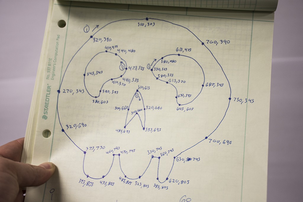
*The 1's in circles dictated which point the shape would start at and in which direction the laser would go.
We plug in the number for our array and:

Okay! Not bad, we've got a little work to do but we're getting close. Unfortunately though, we're back over our 1K limit at around 1150 bytes. So a little more optimization, add the 'turn off laser' array, and flip it right side up, should be a breeze right?
How did we go from around 300 bytes to 1500 bytes when all we did was try to modularize our code? This is where the disassembly window started really becoming the star of the show.
Going through each assembly instruction, we quickly realized that instructions like multiply and divide and data structures like floats were the culprit. Looking at the memory map, we saw that all kinds of libraries were being brought in.
We got rid of floats and started using unsigned chars and ints
void drawLine(uint16_t x1, uint16_t y1, uint16_t x2, uint16_t y2){

	uint16_t dx1 = x1 > x2 ? x1 - x2 : x2 - x1;
	uint16_t dy1 = y1 > y2 ? y1 - y2 : y2 - y1;

	uint16_t steps1 = dx1 > dy1 ? dx1/4 : dy1/4;

	uint16_t Xincrement1 = (dx1*100) / steps1;
	uint16_t Yincrement1 = (dy1*100) / steps1;

	int x11 = x1*100;
	int y11 = y1*100;
	int i;

	for(i = 0; i < steps1; i++){

		x11 = x1 < x2 ? x11+Xincrement1 : x11 - Xincrement1;
		y11 = y1 < y2 ? y11+Yincrement1 : y11 - Yincrement1;

	    	writeMCP492x((int)((x11/100)*16), SSX);
	    	writeMCP492x((int)((y11/100)*16), SSY);
	}
}
With just a few little changes, this brought our size back down to 464 bytes.
Another optimization we made was that rather than calling this function with the coordinates directly, we modified the program a little bit to accept arrays of coordinates. The even numbers in the array would be X values while the odd would be Y values.
We also created an array of when the laser should be turned off. Turning off the laser would allow us to jump from one coordinate to another without being seen and without over cranking the galvos.
uint16_t myPoly[] = {230, 220, 245, 185, 150, 5, 65, 155, 150, 155, 130, 110, 150, 75, 230, 220, 25, 220, 5, 185, 175, 185, 150, 155, 130, 110, 110, 155, 5, 185, 110, 5, 150, 5};
uint16_t polyLength = 34;
uint16_t offIndices[] = {22, 26, 32};
uint16_t offLength = 3;
uint16_t offIter = 0;
uint16_t myIndex = 0;

while(1){
	 for(offIter = 0; offIter < offLength; offIter++){
		 if(myIndex == offIndices[offIter]){
			P1OUT &= ~LASER;
		 }
 	 }
 	 if(myIndex < polyLength-3){
 		 drawLine(myPoly[myIndex], myPoly[myIndex+1], myPoly[myIndex+2], myPoly[myIndex+3]);
    	 	myIndex = myIndex +2;
    	  } else {
    	 	drawLine(myPoly[myIndex], myPoly[myIndex+1], myPoly[0], myPoly[1]);
    	 	myIndex = 0;
    	  }
    	 P1OUT |= LASER;
}
This allowed for the creation of some more complex patterns while still saving as much space as possible.

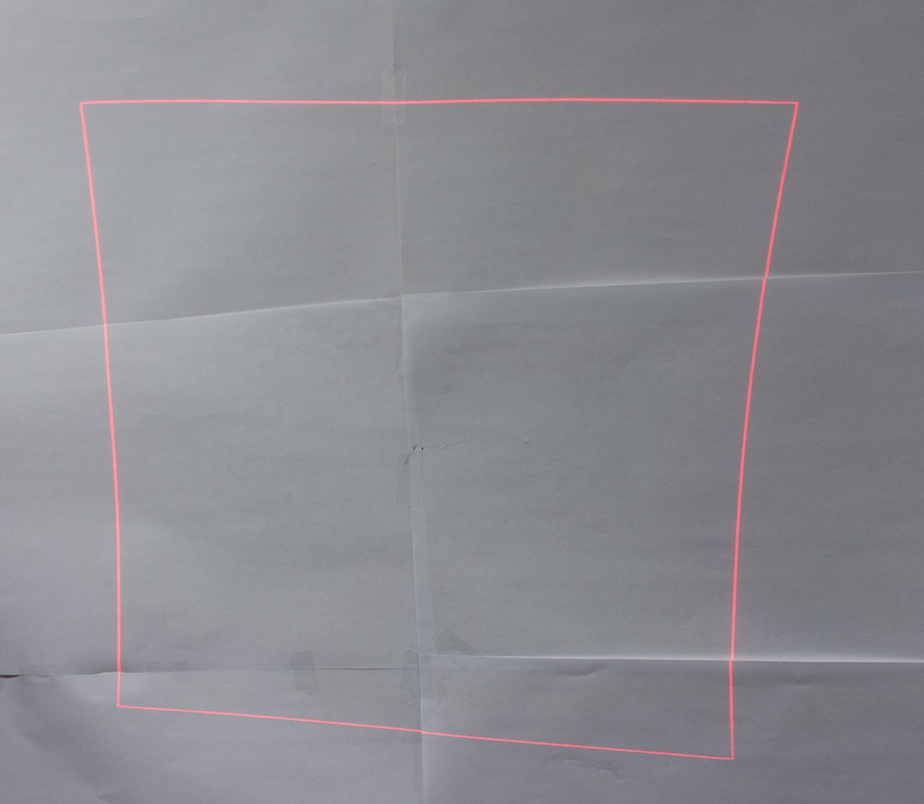
Once we had the laser at the origin, we wanted to draw a square to find the borders of the area we could project in. Using for loops, we iterated through each side.
uint16_t i;
while(1){
	for(i = 0; i <= 4095; i++){
		writeMCP492x(i, SSX);
		writeMCP492x(0, SSY);
	}
	for(i = 0; i <= 4095; i++){
		writeMCP492x(4095, SSX);
		writeMCP492x(i, SSY);
	}
	for(i = 0; i <= 4095; i++){
		writeMCP492x(4095-i, SSX);
		writeMCP492x(4095, SSY);
	}
	for(i = 0; i <= 4095; i++){
		writeMCP492x(0, SSX);
		writeMCP492x(4095-i, SSY);
	}
}
This was the result.
So far, we were only using about 310 bytes of our 1K, smooth sailing!
Now that we knew how to draw lines, we thought that the easiest way to implement the drawing of any shape would be to create a function that took in four numbers: an X and Y coordinate from where a line would start and an X and Y coordinate for where it would end. The function would then find every location between these points and move the mirrors to their corresponding location. This is what we came up with.
void drawLine(uint8_t x1, uint8_t y1, uint8_t x2, uint8_t y2){

	int dx = (int)x2 - (int)x1;
	int dy = (int)y2 - (int)y1;
	int steps;
	if (abs(dx) > abs(dy)){
	    steps = abs(dx/4);
	} else{
	    steps = abs(dy/4);
	}

	float Xincrement = (float) dx / (float) steps;
	float Yincrement = (float) dy / (float) steps;

	float x = (float) x1;
	float y = (float) y1;
	int i;
	for(i = 0; i < steps; i++){
	    x = x + Xincrement;
	    y = y + Yincrement;
	    writeMCP492x( ((int)(x*16)),SSX);
	    writeMCP492x( ((int)(y*16)),SSY);
	}
}

int abs(int val){
	return (val<0 ? (-val) : val);
}
With this, we could feed it the coordinates to any kind of polygon, for example, a hexagon.
while(1){
    	 drawLine(192, 128, 160, 183);
    	 drawLine(160, 183, 96, 183);
    	 drawLine(96, 183, 64, 128);
    	 drawLine(64, 128, 95, 72);
    	 drawLine(95, 72, 160, 72);
    	 drawLine(160, 72, 192, 128);
}
After compiling, our size was almost 1500 bytes! But it worked, so we just had to figure out what was taking up all that space.
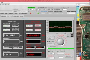
In order to use the DAC, we needed to initialize the SPI on this device as well as create a method to write the DAC values. The module uses an MCP4921 DAC IC which is at 12bit resolution. The voltage conditioners in the modules will scale the min input voltage as zero and the max output voltage as 4095. In this case 0 is -12V and 4095 is 12V making 2048 0V.
Being on the SPI Bus each DAC module is activated using the slave select PIN. We Defined these as SSX and SSY
MSP430 SPI Initialization
WDTCTL = WDTPW | WDTHOLD;	// Stop watchdog timer
	PM5CTL0 &= ~LOCKLPM5;//sets to 12 mh

	CSCTL1 |= DCORSEL_6;//sets clockspeed

	P1DIR |= BIT0 + SSX + SSY;//p1 output
	P1OUT |= BIT0;//set bit 0

	///////////////
	///SPI Int//////
	////////////////
	P5SEL0 |= BIT1 + BIT2;
	UCB0CTLW0 |= UCSWRST;                     // **Put state machine in reset**
	UCB0CTLW0 |= UCMST+UCSYNC+UCCKPL+UCMSB;   // 3-pin, 8-bit SPI master MSB
	UCB0CTLW0 |= UCSSEL_2;                    // SMCLK
	UCB0BR0 |= 0x01;						  // CLK / 1
	UCB0BR1 = 0;
	UCB0CTL1 &= ~UCSWRST;
WriteMCP Routine
void writeMCP492x(uint16_t data,uint8_t ss) {
  // Take the top 4 bits of config and the top 4 valid bits (data is actually a 12 bit number)
  //and OR them together
  uint8_t top_msg = (0x30 & 0xF0) | (0x0F & (data >> 8));

  // Take the bottom octet of data
  uint8_t lower_msg = (data & 0x00FF);

  // Select our DAC, Active LOW
  SSOUT &= ~ss;

  // Send first 8 bits
  UCB0TXBUF = top_msg;
  while (UCBUSY & UCB0STAT);

  // Send second 8 bits
  UCB0TXBUF = lower_msg;
  while (UCBUSY & UCB0STAT);
  //Deselect DAC
  SSOUT |= ss;
}
To run faster we also set the internal clock to run at 16Mhz.
[clock lines]
CSCTL1 |= DCORSEL_6; //sets clockspeedwhile(1){
writeMCP492x(2048, SSX);
writeMCP492x(2048, SSY);
}
The first step is to install TI Code Composer studio and then start a new CCS project for this Microcontroller
Once created Code Composer studio started off with a real basic main.c file
#include <msp430.h>

/*
 * main.c
 */
int main(void) {
    WDTCTL = WDTPW | WDTHOLD;	// Stop watchdog timer

	return 0;
}
Just using main.c we compiled and ran to see where we were in terms of memory
MSP430: There were 46 (code) and 38 (data) bytes written to FLASH/FRAM.
The expected RAM usage is 160 (uninitialized data + stack) bytes.
To fully understand what the code was being used for, we wanted to see the Assembly along with the map file. We enabled these features by clicking Project -> Show build settings.
In the settings, we applied some basic optimization. The first was to tell the compiler to optimize for space instead of speed.
Then under Processor options we set the code memory model to be small. This just tells the processor to use the first 64k of memory. We are unsure if this will help with space but it may make looking at the disassembly a bit easier.
We wanted to see the Assembly files generated by the compiler. So we clicked the option to keep the assembly file as well as add the source interlist so we can see the C code in the comments with the assembly.
And finally we set up our view to show the assembly side by side our C code.
Originally the microcontroller for this project was a Teensy 3.1 which was picked due to its high speed, however once hackaday announced their 1k challenge we figured maybe we can make this laser project do something interesting with only 1k. At the time the boot-loader memory was still being debated on the forms and in a such a space constrained device it is nice to have full hardware debugging where memory/registers can be viewed and instructions can be stepped through. So the Teensy was out and the only microcontroller we had that met these requirements is a TI MSP430FR133 Launchpad kit. As per rules you can use TI Studio on this device for free and get full hardware programming and debugging. This was also a great opportunity/excuse to explore this architecture and learn something about compiler optimization.
This project was originally trying to use a couple SPI DAC modules to control a mirror galvanometer kit that was purchased from eBay. The basic kit included two galvanometers, a stand, two voltage feedback units and a +/- 15V switching power supply. The controller simply takes an analog voltage between -12 and 12v to position the mirror. Our intent was to use our DAC module which is capable of producing that voltage directly via an SPI signal. All components were mounted to a MDF and the laser was held in using a custom 3d printed holder.

Hi,
Can you share a bit about how the hardware is wired up? I have a 20Kpps scanner like yours, and want to control it from an Arduino (or even better ESP32) rather than your MSP430.
Frank


 Roman
Roman
 Pierre-Loup M.
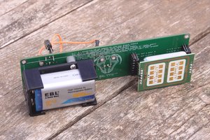
 Capt. Flatus O'Flaherty ☠
 David H Haffner Sr
I appreciate your comments in the code! hope you're still making stuff with lasers.