 Filip Mulier
-
1Order the PC Board and Board Parts
Get 2 copies of the PC board fabricated and order the parts in the board BOM text file x2. One for each channel.
-
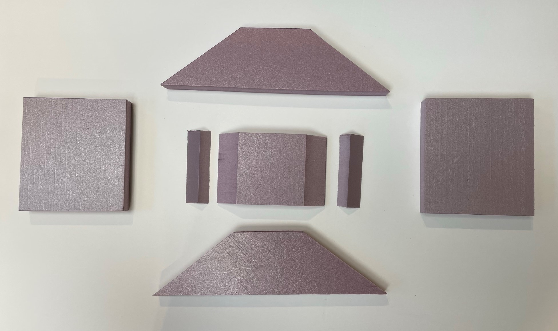
2Cut the Styrofoam Parts
Use a band saw to cut the styrofoam parts from 1in pink exterior construction foam. A 2ft x 2ft piece should provide enough foam for some miscuts. Use the foam cutting layout to transfer the dimensions to the foam board.
![]()
Confirm the angles are correct when cutting. You may need to rig up a fence for the angled cuts on the part labelled Front.
![]()
-
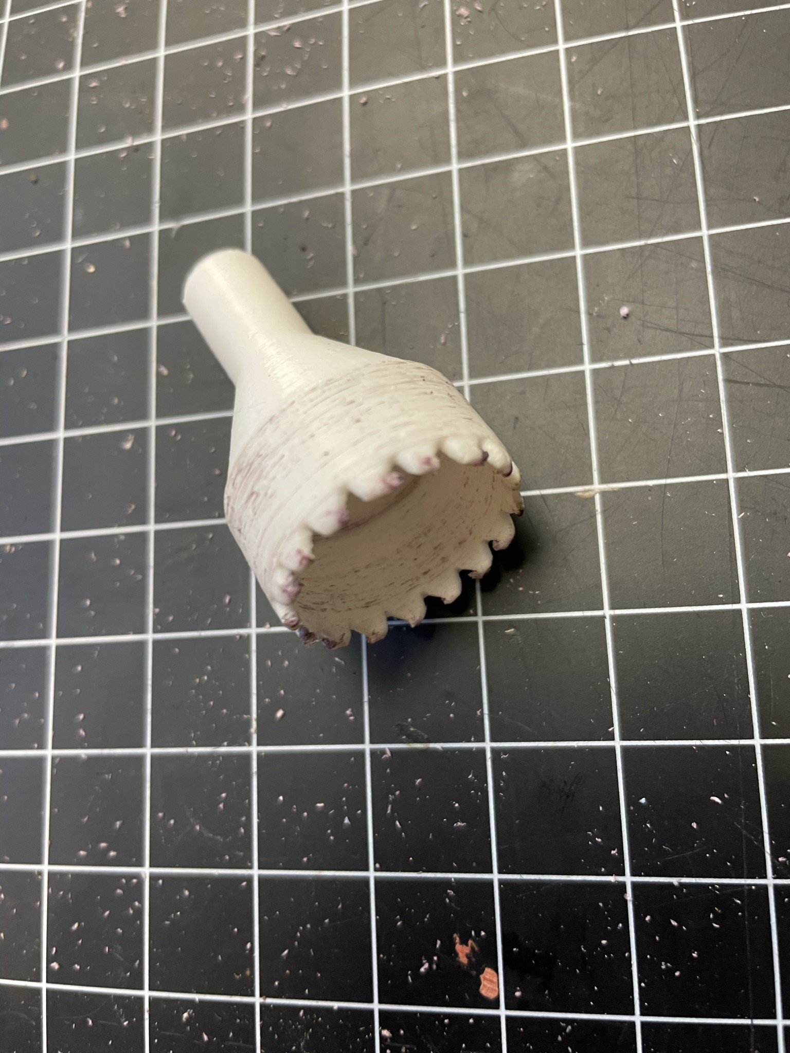
3Drill Holes in Boundary Parts
Note the location of the holes in the boundary parts and drill them with the 3D printed holesaw.
![]()
You might want to practice on a scrap piece to get the hang of it.
-
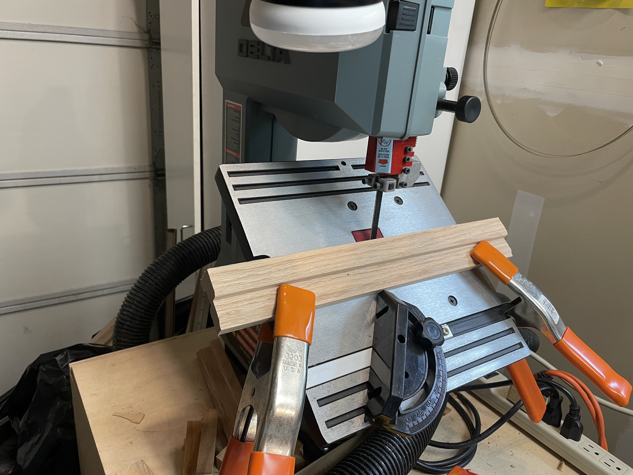
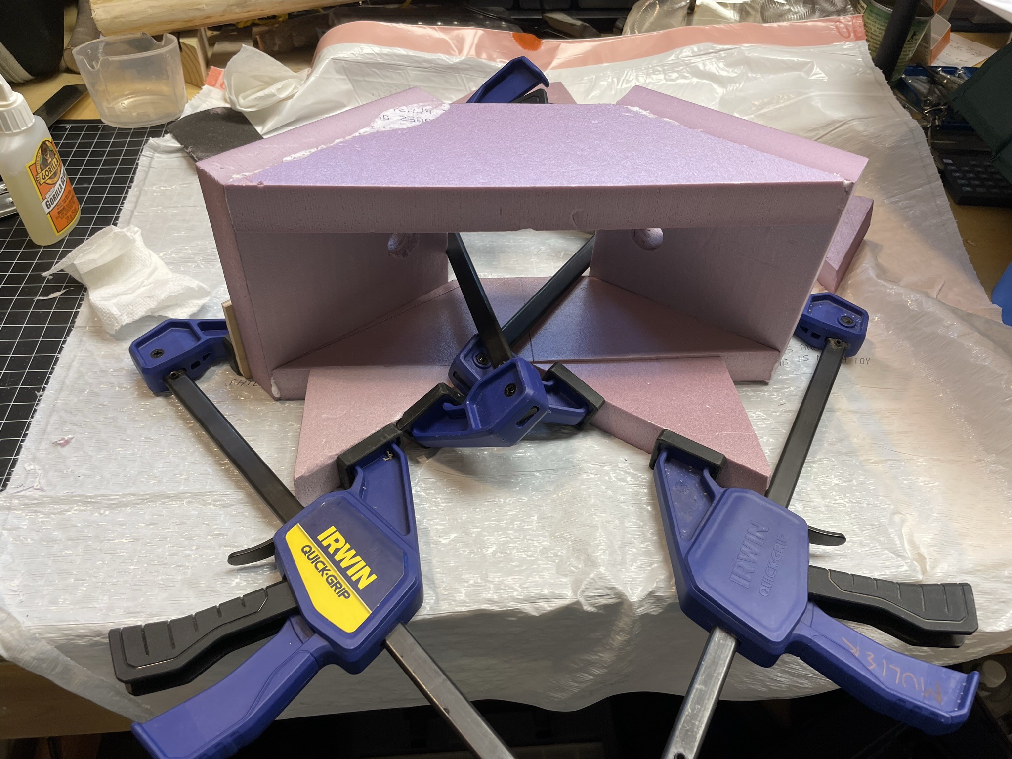
4Construct the Mic Enclosure
Put the enclosure together using all the parts except the Back. You will need to leave the Back off to install the microphones and carpet padding.
Use some rough (80 grit) sandpaper on the surfaces that will be glued, especially the uncut surfaces that have the smooth finish of the foam board.
![]()
Use a white urethane glue (like Gorilla Glue.) You can put a line of glue on one part and then wipe the other part with a wet paper towel before putting them together. The moisture will cause the glue to cure faster and foam up more. Be sure to use clamps to keep the parts together. The glue that escapes the seams can be cut off with a razor knife. This is easier after the glue cures a little and is still soft (but not sticky).

Finished Step. -
5Bore the microphone holes through the enclosure
During the last step you blocked the holes for the microphone capsules. Continue the existing holes you made all the way through the enclosure using the hole saw.
-
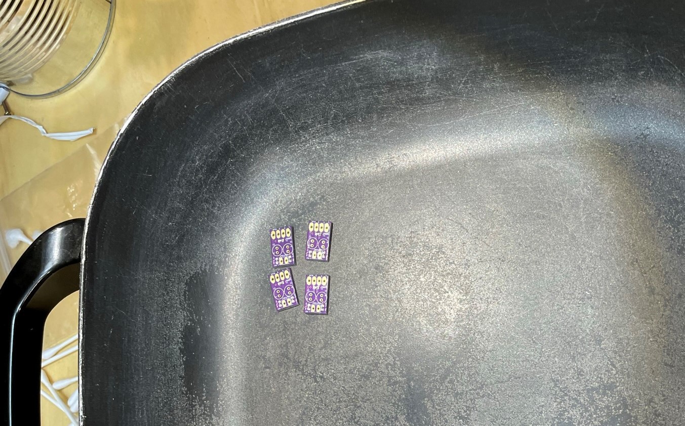
6Populate the PC Boards and Solder the Capsules
Populate the PC boards and reflow them. I use a skillet:
![]()
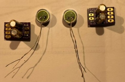
Solder the electrolytic caps and the headphone wire to the capsules. For the capsules you want to minimize solder heat and time as per the datasheet. For the headphone wire, Hackaday has a guide on how to solder that stuff. Headphone wires should be about 2 in long.
![]()
This shows what you should have by now.
Go ahead and solder the capsule wires to each of the circuit boards. The board is marked with the polarity. -
7Solder the Shielded Microphone Cable to the PC Boards
You can use either the fancy Mogami cable which is nice and flexible or you can use some decent shielded usb cable which is not so flexible but does the job. If you use the Mogami you will need to add an extra wire for the capsule bias voltage. If you use the USB, you can use the red wire for that.
-
8Mount the Elastic into the PETG Tubes
This part is a little tricky. Push the elastic mount into the PETG capsule mount tube. You need to push it all the way through so that it can seat properly in the end of the tube. When it is seated the hole that the capsule goes in should be round. You might need to use a small screwdriver to prod the elastic into the groove where it seats.
-
9Mount the capsule into the elastic
This part is also a little tricky. Stand the PETG tube with the elastic mount down. Now carefully push the capsule down into the elastic mount. Your finger will be too big, so use a pencil with a soft eraser to do it. The elastic will hold the capsule snug. Be careful not to stress the delicate wires of the capsule. To hold the circuit board and cable in the tube, I pressed a piece of springy foam into the end of the tube (see picture of next step).
-
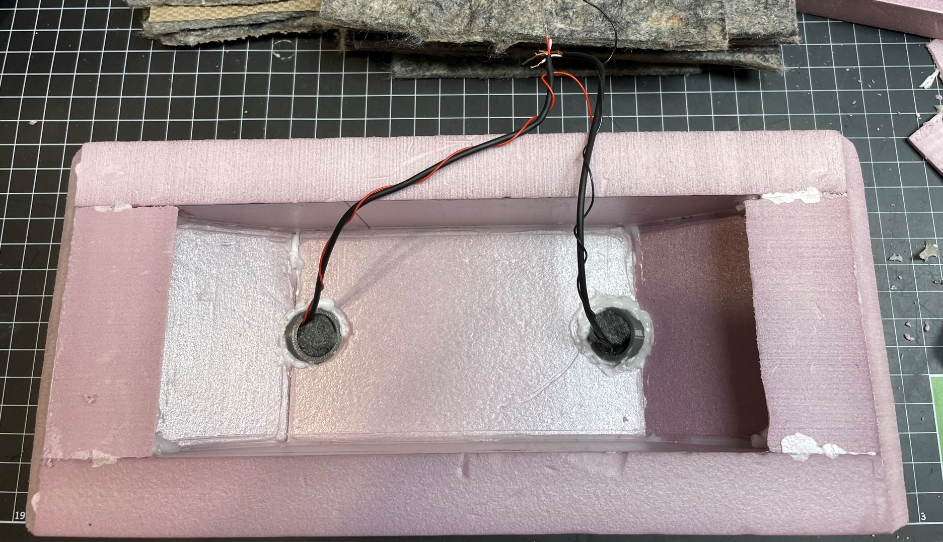
10Mount the PETG tubes into the Enclosure
From the front, push the PETG tubes wire first into the two holes in the enclosure. They should fit snugly and the tube should be flush with the styrofoam surface. Glue the two tubes with the white urethane glue.
![]()
Picture shows the Mongami cables with an external microphone bias wire.
SASS-style Stereo Microphone for Nature Recording
A high quality weatherized microphone for stereo recordings outdoors.

Discussions
Become a Hackaday.io Member
Create an account to leave a comment. Already have an account? Log In.