0%
0%
Cellular conversion of vintage rotary phone
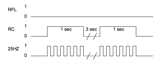
GSM conversion for rotary phone, using Arduino Pro Mini with Atmega328, a QCX601 SLIC module and a SIM800 breakout board.
 Johan Berglund
Become a Hackaday.io member
Already have an account? Log in.
Just one more thing
To make the experience fit your profile, pick a username and tell us what interests you.
Pick an awesome username
hackaday.io/
Your profile's URL: hackaday.io/username. Max 25 alphanumeric characters.
Pick a few interests
Projects that share your interests
People that share your interests


 Josh
Josh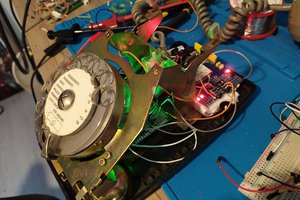
 Proton Gamer
 Marcin Saj
ola
I am building this
but it has problems reconizing the on-hook switch
and the serial gets spammed with sim900 data
can you help me?