Jan
Jan-
Program uploaded
11/05/2018 at 19:36 • 0 commentsJust a quick info: I wanted to translate, clean, better the program and upload it here. Haven't done any of it but the uploading part. It's just the program, which works well. Comments are in German.
Use it, modify it, do whatever you want with it.
Have fun, Jan
-
Adding auto-brightness feature
03/05/2017 at 11:42 • 0 commentsMy recent version of the software does not support auto-brightness. The clocks' LEDs light up at value 64 of a possible 255. This is what I found suitable in a quite bright room, plus you can set the brightness +/- with the buttons on the back.
So, that's not very user-friendly at all. I don't want to manually walk up to the clock, set the brightness to be able to read the time and then be annoyed by the bright, colorful light later at night...
So, I added a LDR/resistor-divider to "control" the LEDs. It's really just four settings:
- midnight
- dim room
- "normal" day, a bit overcast
- bright, sunny day
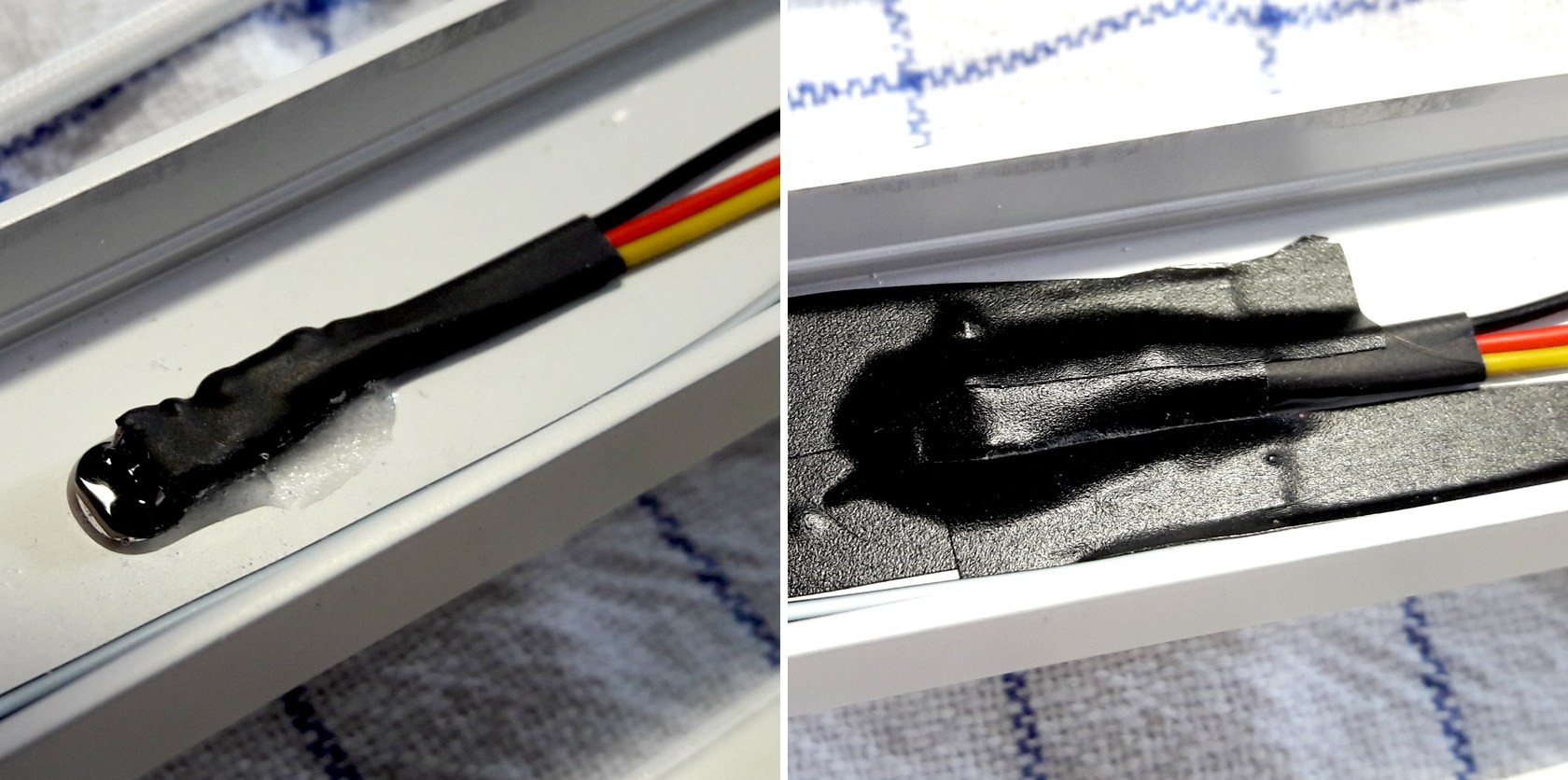
The LDR is a A905014 type, the resistor is a 5% 11K type. The sensor is mounted in the back of the clock because I don't want it to be visible. This means the value has some offset because it's always more or less "in the shade": no problem at all.
Implementation is straight-forward. NO smoothing of the sensor-value, the routine just looks if the value is within one of the four value ranges. Interval is set to 5 seconds, so bright/sudden changes of light won't trigger a brightness-change. There is a hysteresis anyway. It checks if the recent value is at least "amount x" lower/higher than the last reading. All values were found by trial and error. I found the LDR datasheet of no real use. The stated values are all widely spread.
The sensor is glued in and covered with black tape to make sure that no light from the strip or Arduino LEDs gets to it...
![]()
-
Pitfalls and things I'd do better next time...
02/17/2017 at 16:43 • 0 commentsToday I'd like to talk about what really annoyed me while building the clock. There were a few occasions I'd rather throw everything into the next corner than continue working. It's always worth looking at those mistakes to not make them again, right?
Case and front plate
- Using the smallest possible profile because design
This one got frustrating really quickly. I chose this particular profile to be pretty against the wall. This led to a "everything has to be cramped into the case"-situation. With the front plate pressed in there's as little as 0,5mm space left at some spots. I had to open and close it often to check for proper fit of this and that.
Solution: Don't be too selective next time regarding looks but think more about assembly! - Screws are bad, like really bad?
Deciding to not use screws in any visible part of a design does need a lot of thinking to get it straight. It worked for me but was a PITA to get right.
Find the proper dimensions for the interference fit between front plate/spacer and profile. Working as an mechanical engineer helped a lot to get it right first time but anyway: Things have to fit properly and be easy to (dis)assemble. You have to guess the profiles springiness and hope that the laser-cutting company complies with the theoretical dimensions you sent them.
Solution: Regarding clean look there's not much to do here except maybe using different techniques (like clips or magnets) or really pretty, hard to get screws. - Start building stuff without thinking everything trough
This is a general problem I have with most of my personal projects. I think like "ah, this is a detail I can wrap my head around later". Noooope, doesn't work that way. Just finish your whiteboard or CAD session like you're supposed to and get to work when everything is sorted out.
That's about it. Won't make these mistakes again. I hope.
- Using the smallest possible profile because design
-
Finished clock
02/05/2017 at 14:40 • 0 commentsYay!
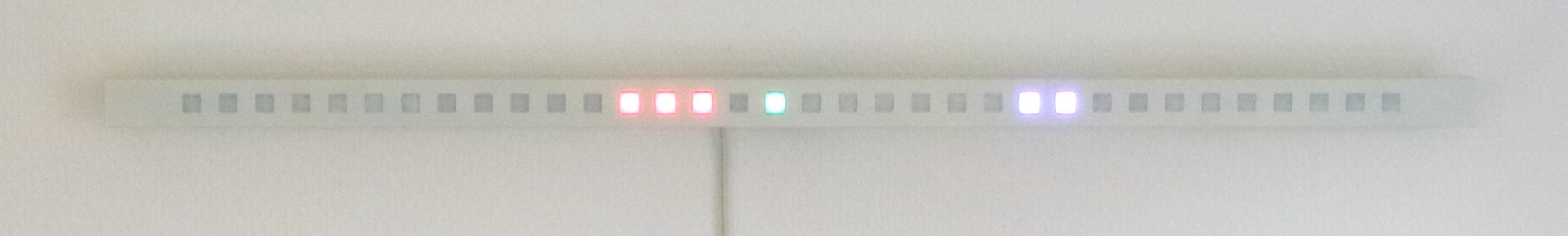
After a long time of absence (and other projects in abeyance) I present you my latest, finished project. To keep it short - a detailed build log is in the works - I'll just show you the finished clock. It's as simple as counting a few dots and summarize them.
Yes I know, nothing beats a nice, round standard clock in terms of readability, but if I wanted a standard clock I would've bought one...
![]()
The system is simple: from left to right: Red = hours 1 - 12, green = decadic minutes 10 - 50, blue = single minutes 1 - 9. Better pics will follow, I promise! See gallery for a few additional pics. The ones I took are a bit washed out color-wise and really don't do it justice.
Have a look at my
-
Building the clock
12/10/2016 at 17:25 • 0 commentsBuilding the clock
Design (preliminary considerations)
Mode of operation
- time mode only, in minute-precision
- no numbers, layout as a straight line of "RGB-pixels"
- keep time when mains power is switched off
Case
- sleek, flat design, preferably white
- no screws or electronics (e.g. parts of LED strip) visible
- individual pixels easily distinguishable
- pixels rectangular or round
Those were the first few thoughts I wrote down. Of course everything got more refined as time went by. But the fundamental mode of operation has been in my mind for a long time:
![]()
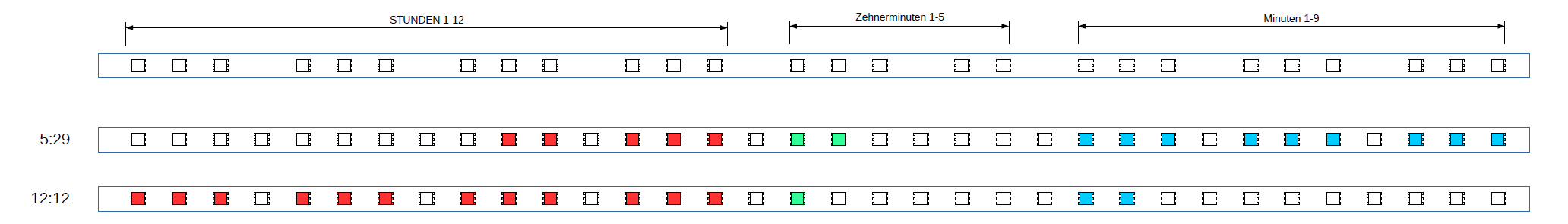
In a industrial design book I read something interesting: The human brain isn't too good at perceiving groups of more than 4 numbers/dots/somethings close to each other in a given (short) amount of time. Groups of three on the other hand are easily human-readable. So I decided to use groups of three LEDs with one LED off between them. The "divider-LEDs" themselves are left in place, for possible future use.
After all dividing 12 hours / 3 and 9 minutes / 3 makes perfect sense. Hours are red, decadic minutes (only exception here: grouped as one set of three and one of two LEDs) are green, single minutes are blue.
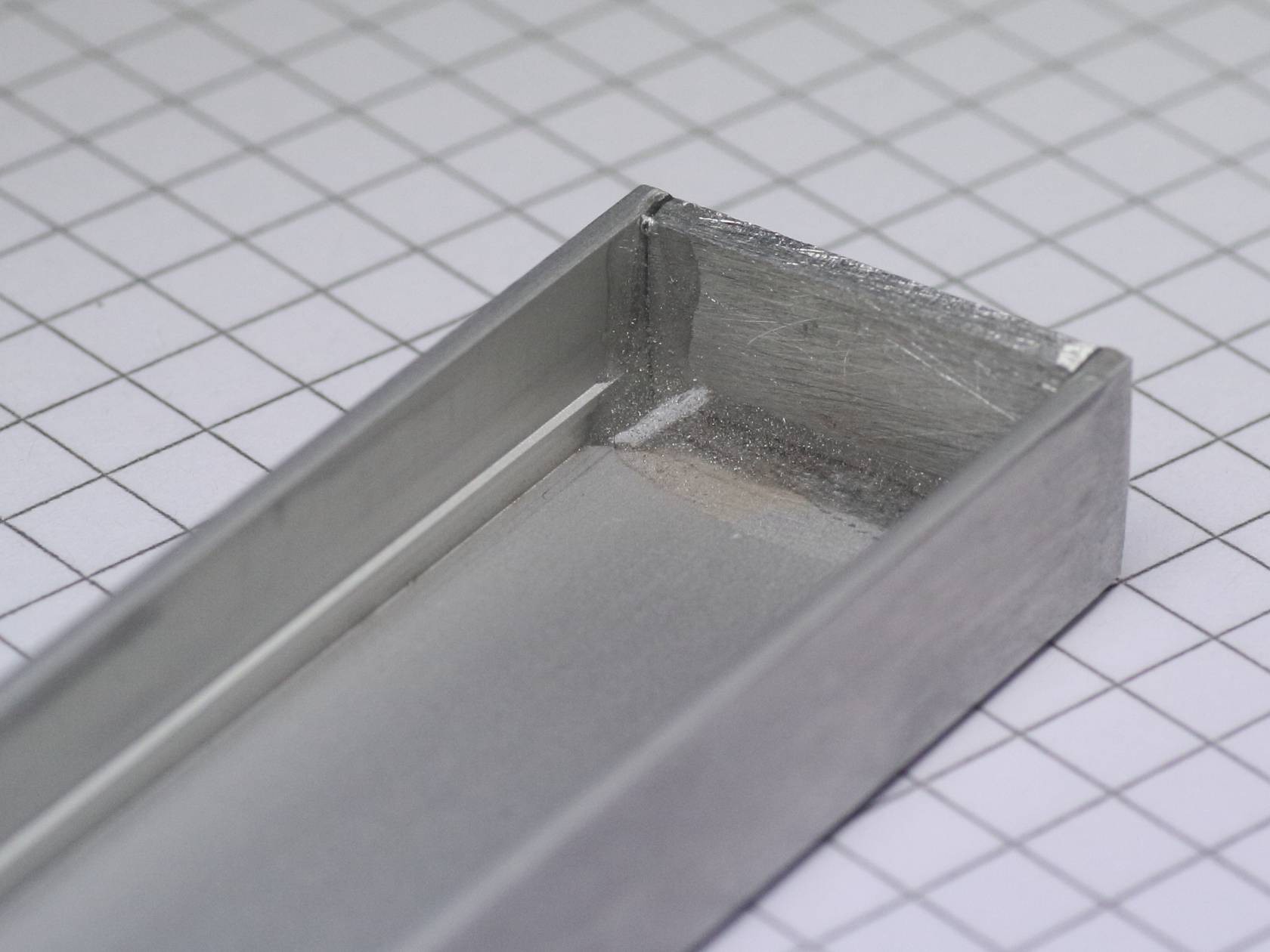
The enclosure
I needed a profile which had enough room for the Arduino and RTC on its breakout board (both around 18mm wide), but not too big so it won´t look clumsy mounted to the wall. Found that at the local hardware store.
The profile-heads are closed with aluminium plates. One plate is glued in place, the opposing one is held in place by two magnets to allow easy access to the USB-Port of the arduino for future programming.
![]()
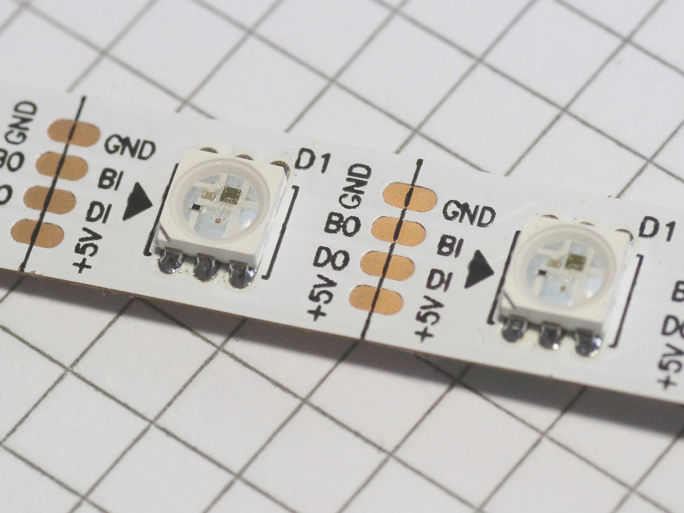
I chose the WS2813 over the WS2812B LED strip for a reason: It has zero external components on it.
![]()
This way I could easily glue the strip directly to the spacer plate with double sided tape:
![]()
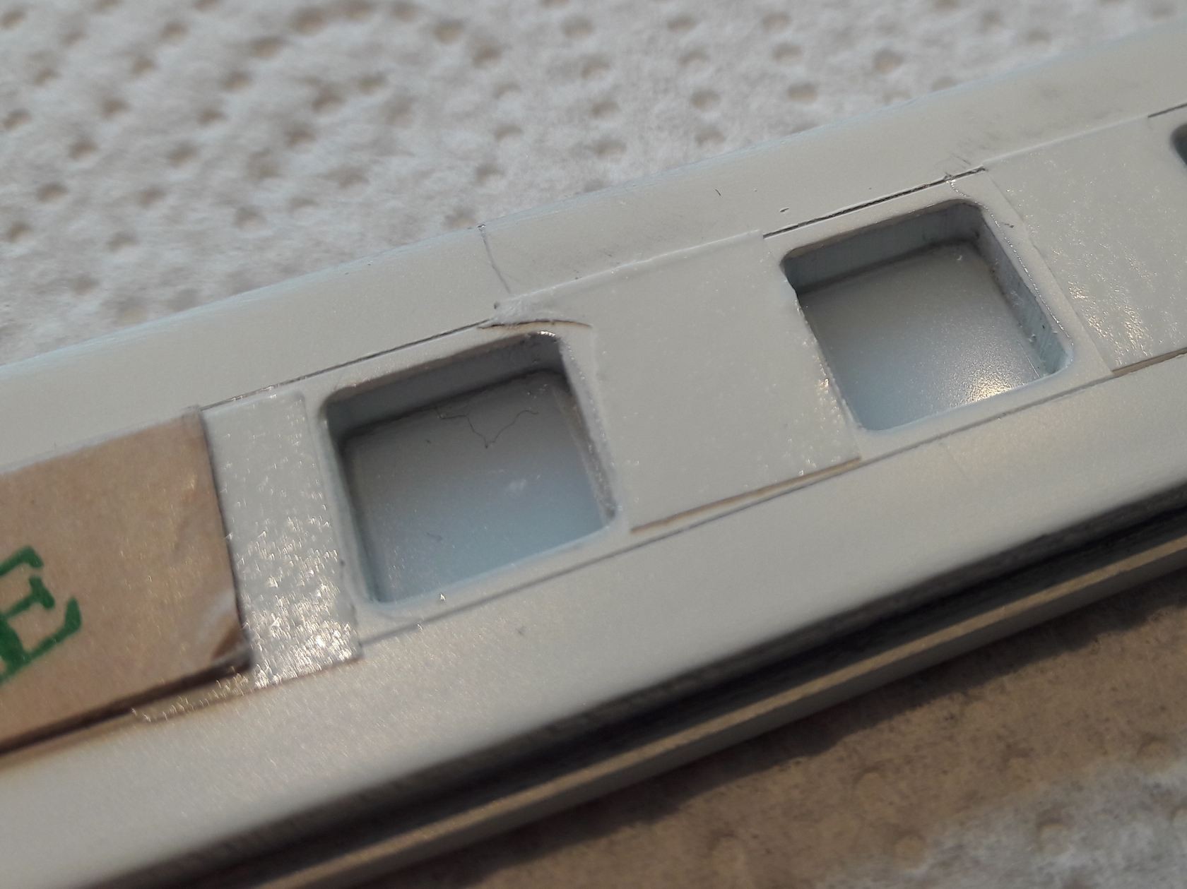
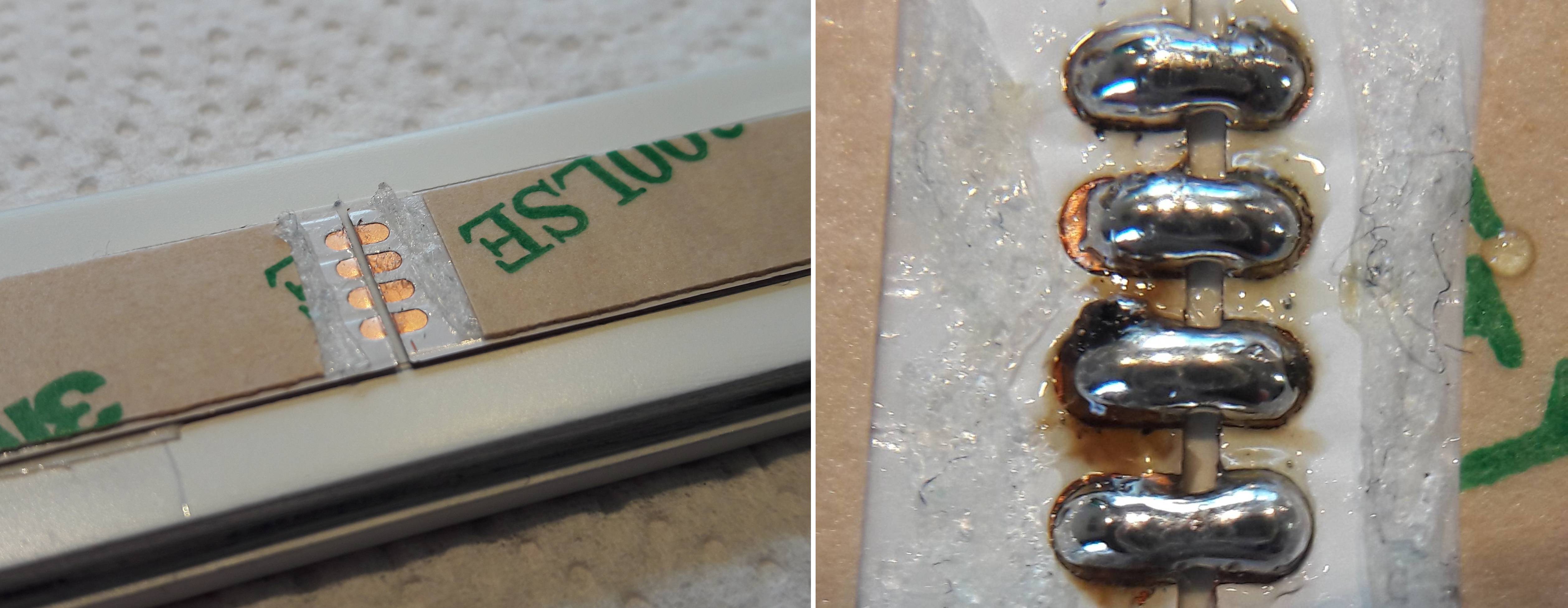
Turns out the spacing between the LEDs does not match the openings exactly. So I had to cut it three times. As I used the LED-side for mounting, I needed to use the contacts on the back of the strip for connecting the parts back together. Contacts are buried under glue which had to be peeled away before soldering:
![]()
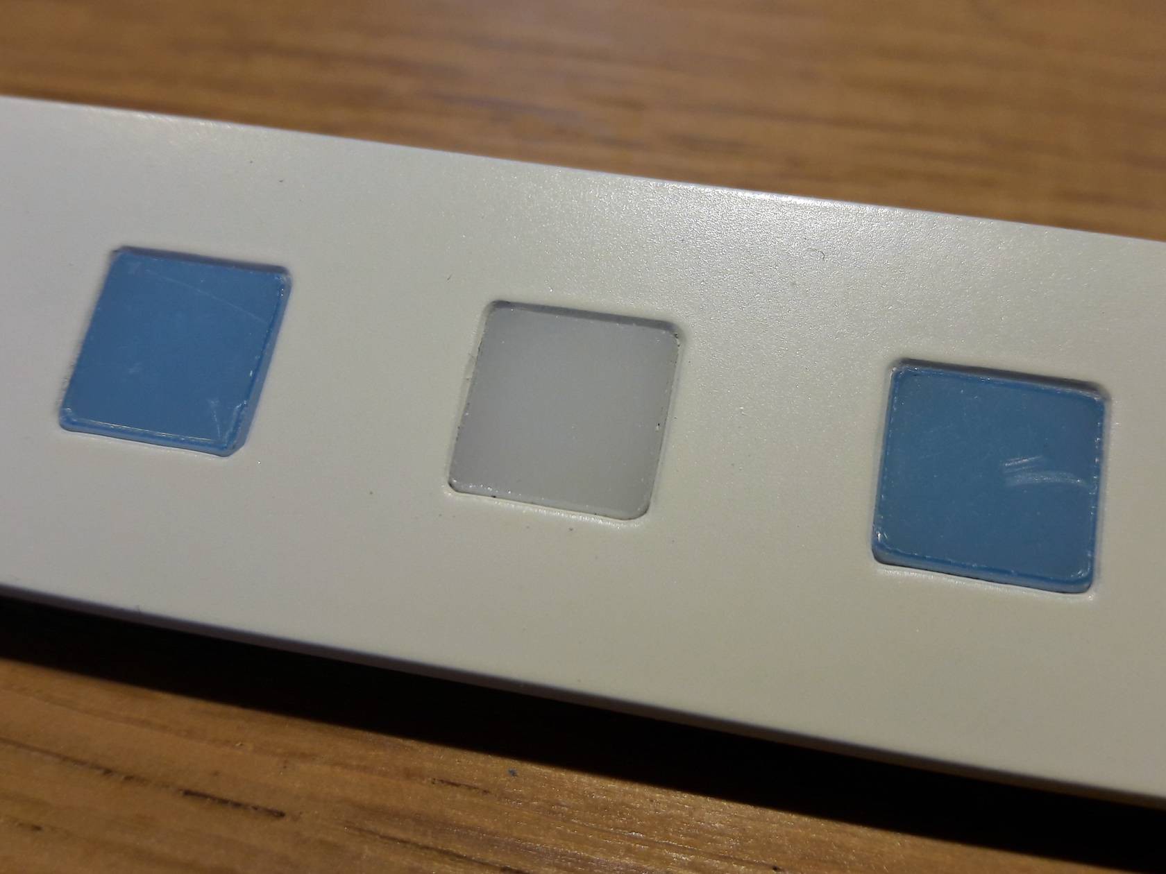
The opaque (translucency 49%) windows are laser-cutted and around 0,1mm wider than the rectangular openings in the front plate. They are pressed right in (blue = protective foil):
![]()
For mounting the front plate to the profile without any screws, it is first glued to a spacer plate which is 0,2mm wider than the profiles inner width. Everything is painted in matte white after assembly.
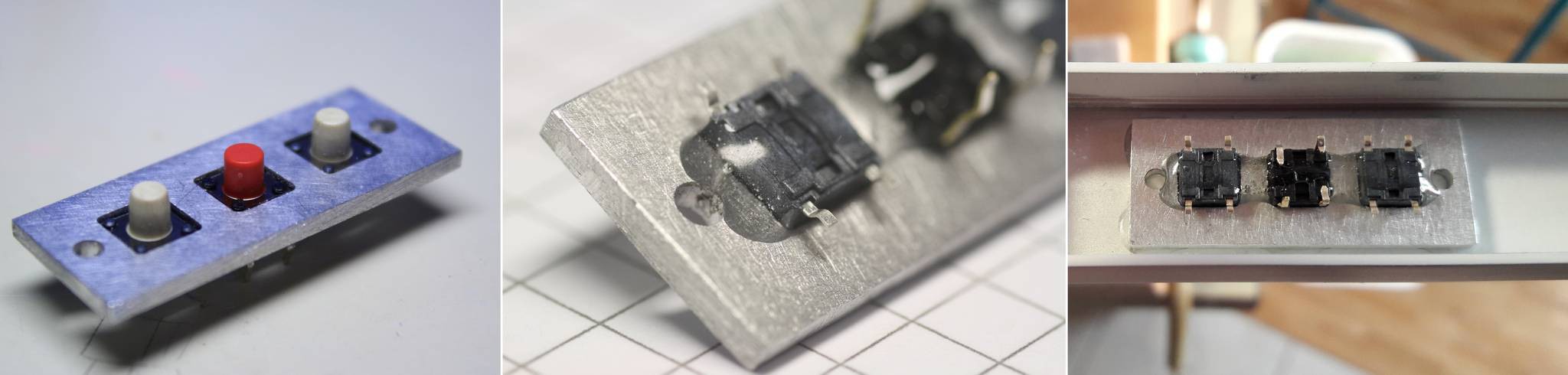
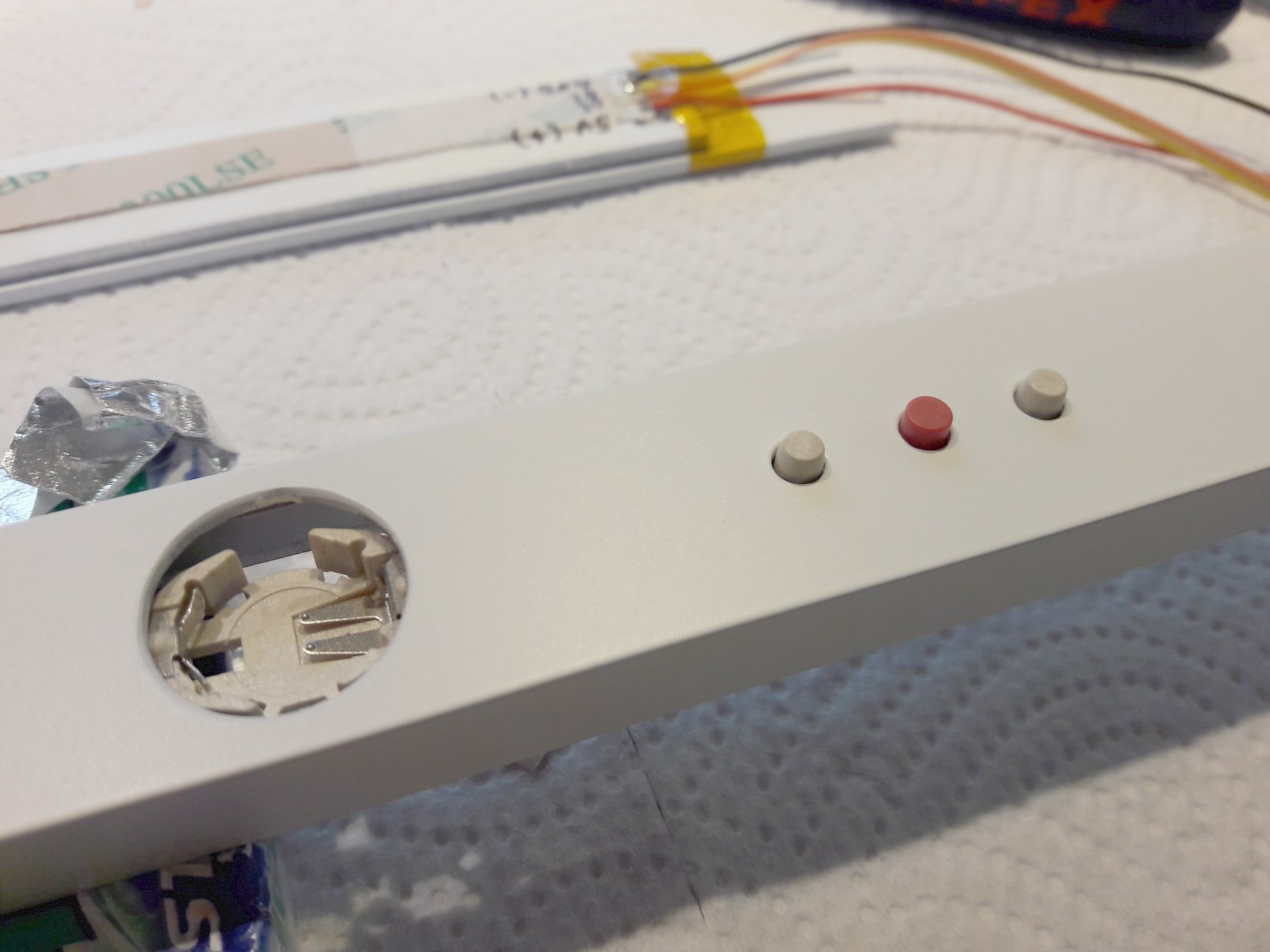
Only three buttons are needed to set time. MINUS, SET, PLUS. These are glued to a aluminium plate which is glued into the u-profile. No need to use screws here as I don't think I'll need to replace these buttons in a hundred years (they are not used often after all).
![]()
I wanted the power cord to be as "invisible" as possible but not a standard wrinkly off-white USB cable. So I bought some white braided glass fiber sleeving. It does look very clean against the white wall. I soon gave up trying to get the wires through the sleeve.. Fortunately a friend who does a lot of "PC-supply-wires-through sleeves"-stuff did this annoying work for me!
Wall mount
Requirements for the mount are as follows:
- max. distance to wall 20-30mm
- mount not visible from the usual field of view
- easy to adjust tilt and rotation for leveling
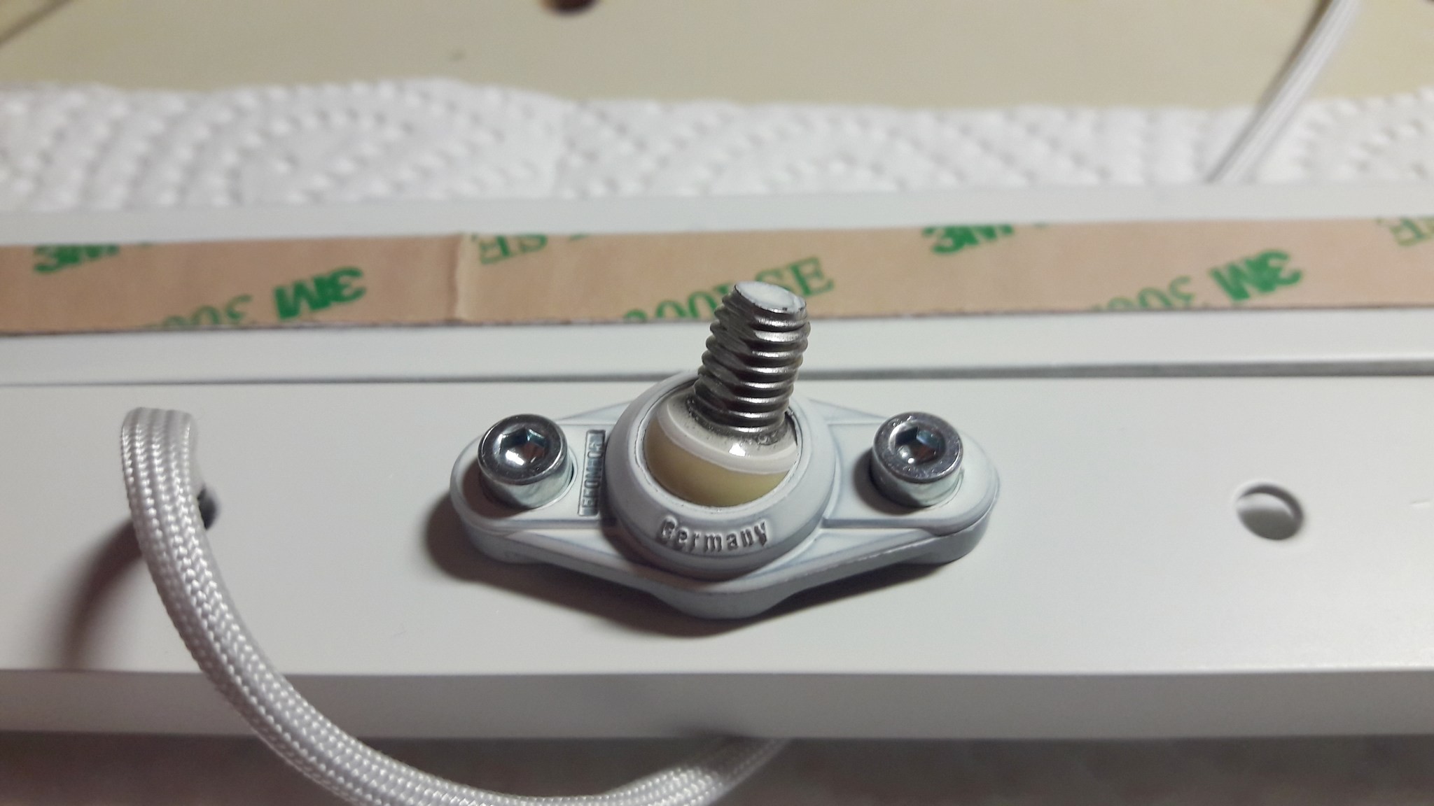
I tried lots of (overly complicated) designs in CAD but found the solution in my parts box. A 5mm plastic flange bearing. These feature 360° rotation and tilt angles of 29°. A quick test showed enough friction of the bearing in its socket to keep the clock in place once aligned. I tapped the 5mm hole with a M6 thread, screwed in a 20mm piece of threaded rod and secured it with a dab of glue.
![]()
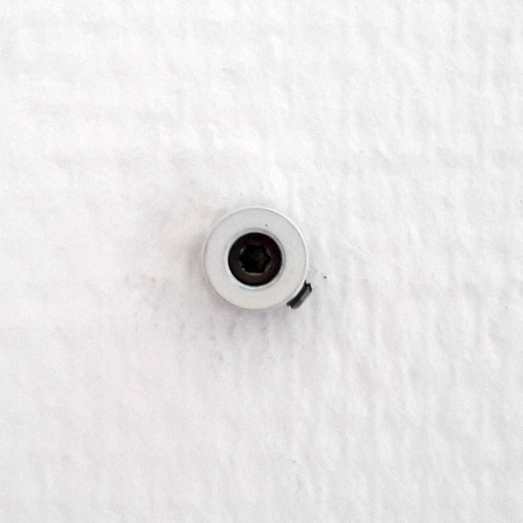
The part secured to the wall is a washer soldered to an adjusting ring:
![]()
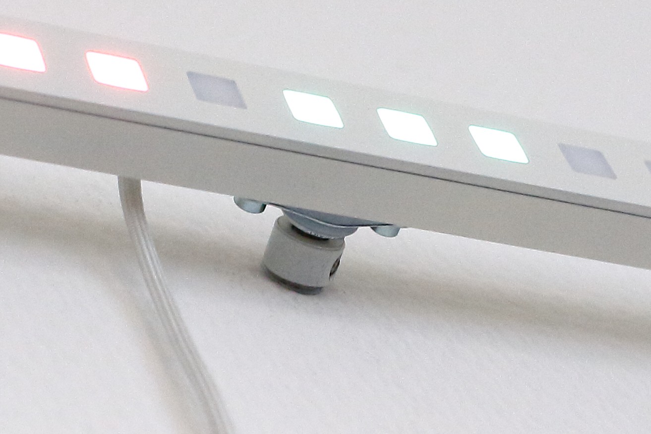
The chipboard torx screw-head had to be sanded off slightly to fit into the adjusting ring. This is how the mount looks like:
![]()
The circuit
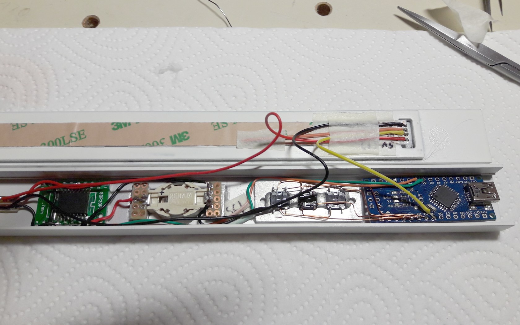
"Circuit" is grossly overstated here. It´s just the RTC (with a backup coin cell directly soldered to it), three buttons and the LED strip soldered to the Arduino:
![]()
![]()
Both PCBs are held in place with a few dabs of hot glue. With all LEDs at full brightness, the whole circuit consumes around 5V/1000mA. So I chose a standard USB charger rated at 1,5A.
Software
To keep it short: A state machine, a few functions to convert the RTC time to LED pixel numbers...
Anyway: big thanks to the creators of the following libraries (and of course the whole arduino community).
Linear RGB LED Clock
A unique way to display time. Designed to be easily readable. Just count the colored dots!