thpoll
-
Instructions are Ready!
09/09/2023 at 20:13 • 0 comments
Yes, finally I got the build guide ready on my HW github repo: https://github.com/thpoll83/PolyKybd
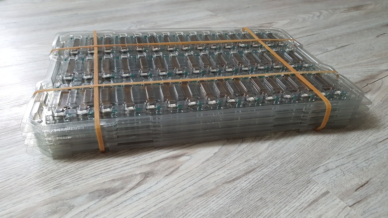
I wanted to wait for my first batch of pre-production displays to be showcased in the instructions (along with the regular soldered ones, you have the choice) so there was some delay. The first batch:
![]()
Around 500 displays, all with long enough FPCs to directly connect to the socket! No more FPC-toFPC soldering needed :)
With that, the build guide is finally out! It contains a lot of pictures and was more work than expected. If you are impatient and you do have a hot-air rework solder station, you can go ahead and start putting a PolyKybd Split72 together :)
If you don't feel confident enough for the FPC soldering part or you don't like to buy all the different parts across various sources from the internet... Stay tuned! As you may know from previous post I'm trying to put a kit for PolyKybd Split72 kit together, just don't expect it next month or this year for Christmas.
And I can also tell you that the new displays are much smother in operation compare to the old ones, where I extended the flex cable!
What else happened?
Besides a little summer vacation (yes I need a break from time to time too) a VERY similar project came up: https://www.kickstarter.com/projects/daptkey/daptkey-redefine-your-life-with-a-customizable-keyboard/description
They "had" the idea withe the OLED displays in October 2022🤔
Not sure what to think about it. They use James Brown's mechanical solution of a separate slot in front of the key switch and the flex cable comes out at the bottom edge of the key cap. I do wonder if there is any mechanism implemented to reduce the OLED burn-in? From the video, I would rather say no. Granted, the look of the case and caps have a nice finish and these guys moved quite fast from development to production.
What are your thoughts? Let me know in the comments below!
-
Customized Displays Arrived!
07/14/2023 at 10:58 • 3 comments
Here they are! It maybe doesn't look like much, but this is really a big step forward: The first 2 prototypes of the displays with the extend length FPC straight from the factory.
Maybe not such big news for all Ko‑fi supports, as I already announced the work on this in a private post some time earlier. Still, I'm happy, that I was able to get these 2 prototypes and soon a few hundred pre-production samples without ordering 10.000 pieces right away!
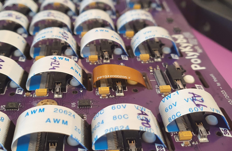
So, here you can see the first one fitted into my prototype with all the other displays:
![]()
By intention these are just a bit shorter than the manually extended ones to reduce the needed space below the PCB, since there is even more space requirement when pressed. And I'd like to avoid the cable touching the case as it adds extra resistance when pressing:
![]()
There is still some wear from the rough edges of the FR-4 slot and I've been toying around with plastic inserts to give it some more protection.
However, that didn't lead to a good solution yet and it might the easiest to just a apply a bit of thick paint/coating around that edge.
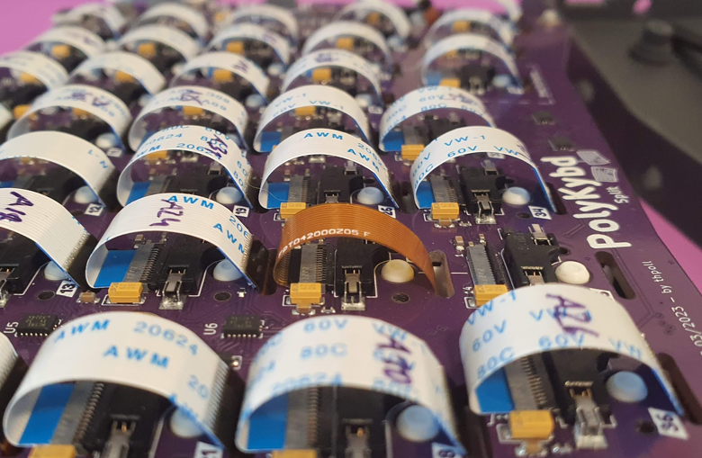
From the outside the new displays look almost identical:
![]()
(first row in the middle)
From the first picture you might have noticed that there is no hatched copper fill on the backside of the FPC. With the absence of that, the flex cable got much smoother and the typing experience in my opinion improved a lot now :)
Keycap Orientation
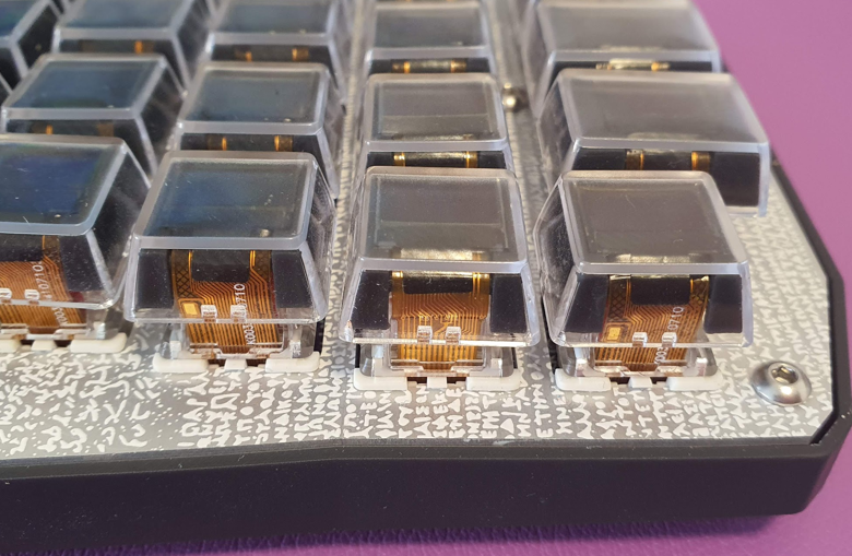
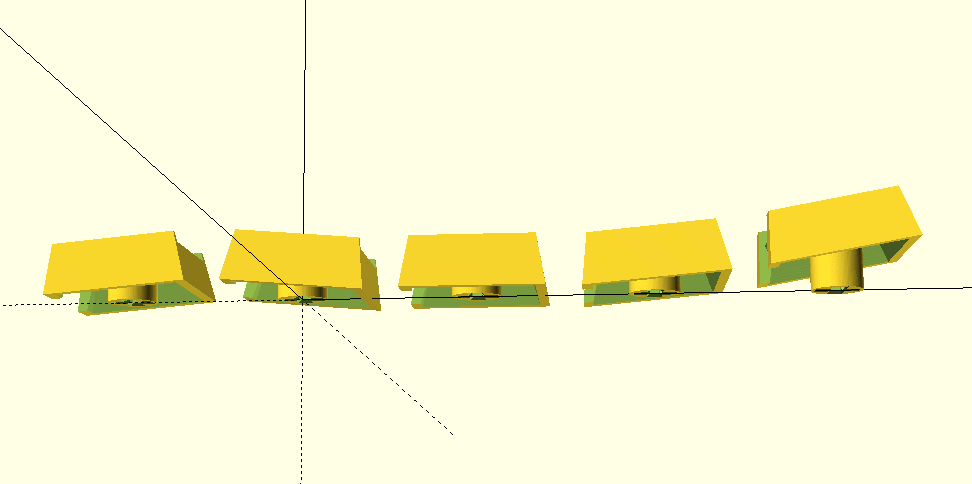
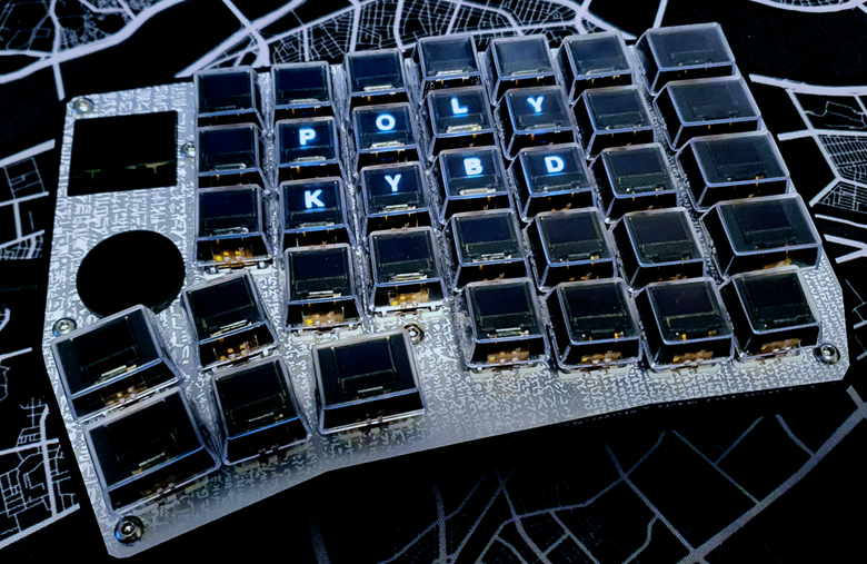
Apart from these great news, I have been experimenting with the orientation of the keycaps:
![]()
I find it a bit difficult to always find the right row, if all keys are uniformly flat. There is a little notch for the index fingers, but still I do hit the wrong key from time to time. This could be a matter of taste, but I also hope to improve the ergonomics with this little tweak. In the end everybody can choose the right profile according to personal preference. Here a photo from the second prototype I'm putting together:
![]()
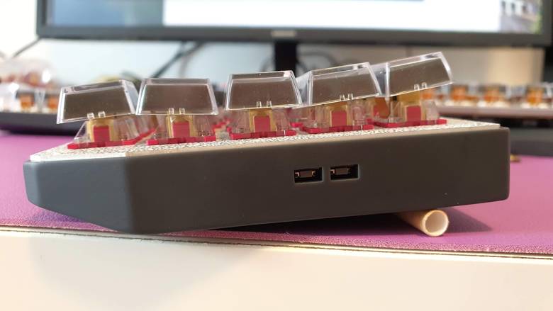
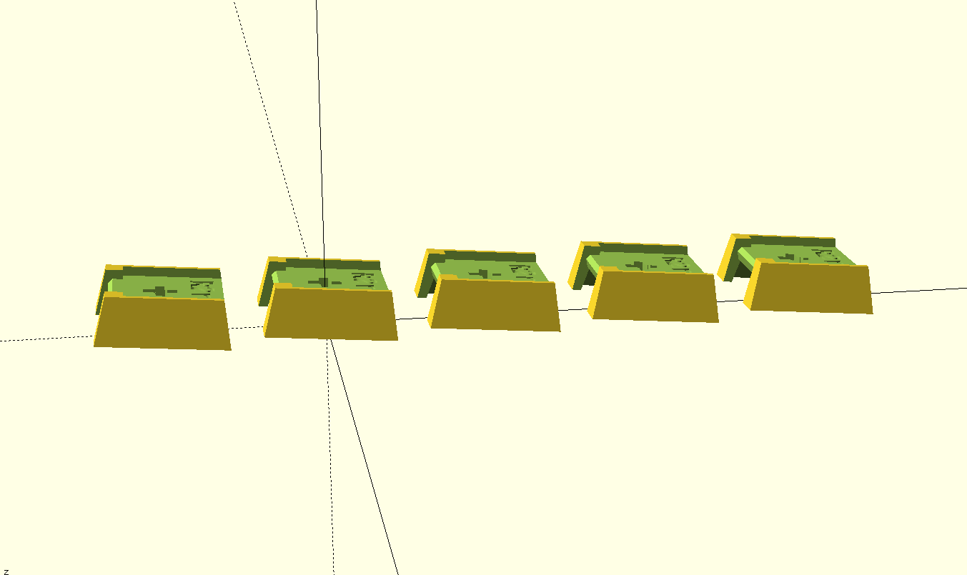
The next possibility that comes to mind would be a slight step between each row like most commercial keyboards have:
![]()
In that case you might need some tenting. Or you just come up with you own version. The stems are made in OpenSCAD:
https://github.com/thpoll83/PolyKybd/blob/master/keycaps/keycap_stem.scad
It should be rather easy to customize. The only limiting factor is the length of the flex cable.
Repository Cleanup In Progress
Yes, the long promised cleanup of the repository is in progress an I'm writing a short build guide. More on that next time..!
Thanks, Thomas
-
Finally, After 2,5 Years!
05/24/2023 at 05:06 • 0 comments
It is finally working! Both sides can be used without modifications! 😁
![]()
But that is only for the hardware of course, software is never done as we all know!
Current Software Work
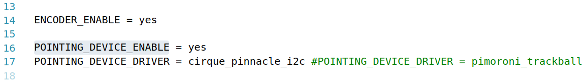
The code is already much cleaner and my current schedule is about testing through the optional devices like rotary encoder, pimoroni trackball and cirque trackpad:
- The rotary encoder works.
- The pimoroni trackball needs a QMK update as it has some issues in my version (the cursor becomes very shaky). To be done soon...
- The 23mm cirque trackpad works after resoling some configuration issues. It is a bit small, so I might try the next size as well.
![]()
Open Software Issues
- The status display on the right side (slave) turns on unexpectedly after the turn-off timeout (just resolved minutes ago, so this is also done)
- An issue I had in the past: RGB LED matrix flickers on the master side. Maybe because I changed the LAYOUT macro to reflect the key orientation..? Need to check if I have to do the same for the led_config.
- Easy way to configure the layout. Right now I still have to flash the firmware every time, but at some point I would like to switch to something like Vial so that can be done without flashing anything.
- Some more Icons for all the special function keys.
So you see, there is still plenty of work left.
Further Software Improvements Ahead
- This is out of scope for now but definitely the goal: To have a program on the host side to switch the OS input language and also send program context information to the keyboard so that customized symbols can be displayed.
- To avoid burning out the OLED displays, I plan to shift the displayed content slightly once a while. This is nothing fully developed yet, more an idea.
Final Touches
The PCB is in a production ready state, however I would like to apply a cosmetic change to the silkscreen (some pin markings are on the wrong side - luckily only on the silk screen).
And this is more about the general mechanical design:
If possible, I would like to have some plastic inserts for the flex cable slots:
![]()
With that, the edges would be soother and make the flex cables maybe life longer. I had no such issue so far and the edges are not rough, but if it is possible, I'd like to try. It sounds like an improvement to me. I was also thinking about plated slots, but these have size limitations which makes it impossible (at least at JLCPCB).
Layout
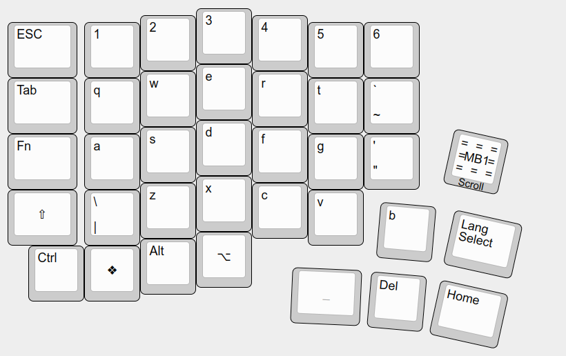
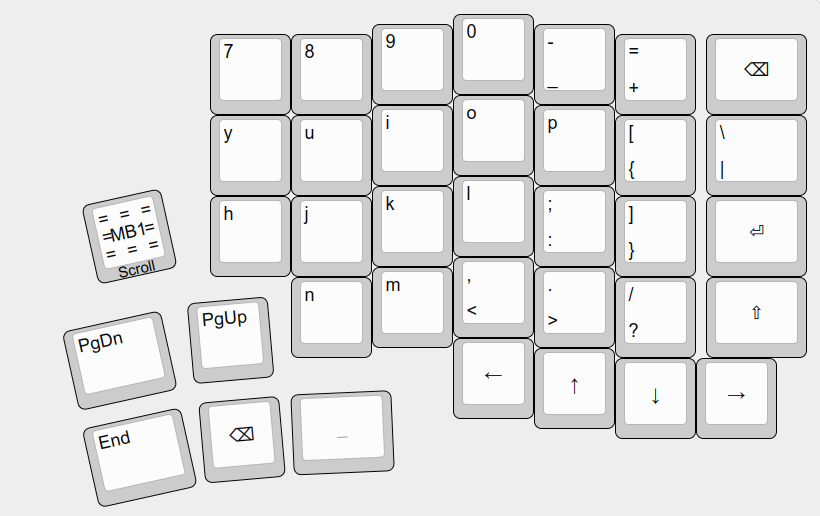
Of course everyone can come up with an own layout, but let me quickly show off my current choice (and might change soon again):
![]()
![]()
I started with a symmetric layout similar to Ergodox. With the number keys 1~5 on the left side and 6~0 on the right and in a similar fashion distributed the letters.
However, I'm really used to the traditional stagger and there, the left and right hand finger assignment is distributed rather un-symmetrical. Maybe this changes at some point, but for now this layout is much easier to type!
Your perfect layout might look different... let me know in the comments below~
-
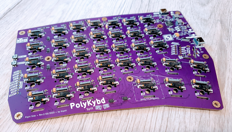
Revised Left Side & 3D Print Fine-Tuning
04/27/2023 at 05:20 • 0 commentsAs promised in my last post, I transferred the (for now) finalized PCB design from the right to the left side and already ordered 5 assembled boards that are in production right now!![]()
The same thing was needed in the past when transferring the initial PCB design from the left to the right. This time, it turned out less painful (TBH I would like to automate a lot of things, maybe with skidl and pcbflow as mentioned in that article: https://kbd.news/Keyboard-as-Python-code-1834.html).
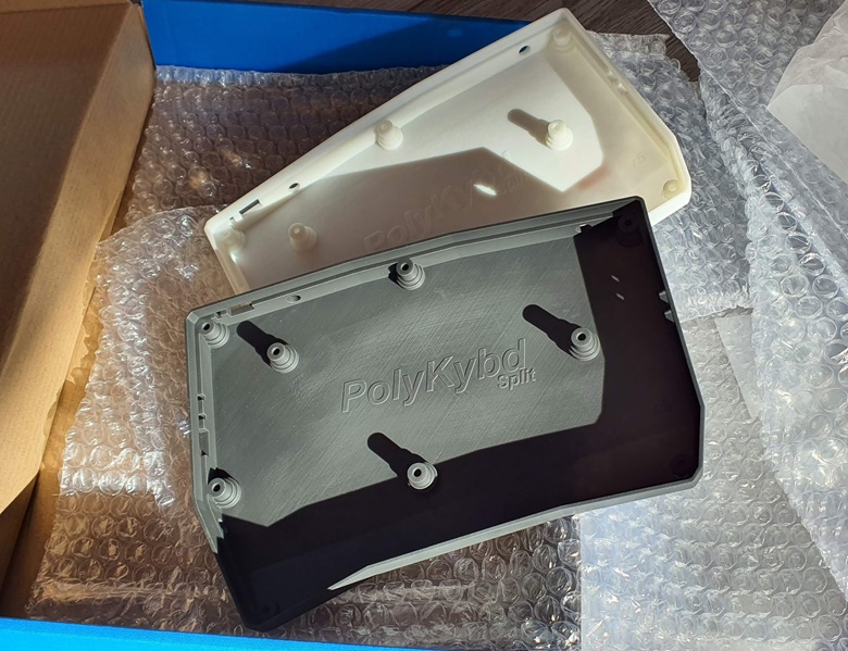
At the same time, I was iterating on the 3D resin prints. Here is the case, which was an almost 100% fit. I did print it first on my FDM printer before, but the tolerances are just a bit different:
![]()
The gap between plate and case is a bit larger than I wanted it to be. The fix was easy and the new version should be spot-on!
On the picture above, the print looks a bit scratchy from the post processing, but it is not so pronounced under normal light conditions. In fact, I was surprised how great all the parts turned out.
Only on my second batch, I had a few parts with some excess material here and there, that in my opinion, comes from a faulty resin printer LCD/mask:
![]()
You can see a little blob on the middle element. I hope that was just a one-off issue.
The cirque trackpad mounts do fit. However, I have to raise them a bit higher from the plate, otherwise the finger drops too much down when reaching for the trackpad. Also, the keycap stems need some more tuning:
![]()
While I can just push the FDM print onto the MX-cross of the switch, the resin print is not so flexible and then sometimes cracks. Making the cross cutout at the bottom just a little bit bigger should fix that.
While waiting for the assembled PCB, I'm working on the software side and it is about time to do that :)
-
Revised Right Side: Final Version?
04/08/2023 at 14:59 • 2 comments
If you have been following my blog posts, you know that a little mistake with my last PCB prevented me from using it as a keyboard: Pin 1 of all OLED displays was on the wrong side.
So I had to route half of the PCB again... Of course I took the chance to rectify some things I was not 100% happy with in the first iteration.
![]()
Right Side V2 Changes:
- The RP2020 and flash memory moved about 10mm away from the switching regulators as the space in between was very tight.
- The reset and boot button, as well as the debug port moved to another location as it turned out inconvenient.
- The host USB-C port got an ESD protection chip and I added a resettable 300mA polyfuse to the board to give it perfect protection in case of shorts or similar.
- The non-inverting buffers I used were actually for 5V and not 3V3 so I decided to change them with similar ones, now matching the supplied voltage (even though they worked without any issue).
- I set the current limit for the the displays and LEDs to 250mA as all displays together could potentially draw much more current (all pixel on + max brightness), not even considering all LEDs set to fullbright. Why 250mA? The USB 2.0 specification has a limit of 5V at 500mA (2.5 Watts). With both sides connected (2x250mA) and a display voltage supply of 3.7V I could reach 1.85Watts. That leaves enough room for 2 MCUs, 2 status displays, some other components and losses (also the switching regulators are not perfect). If it turns out to be too strict, I can set it to a higher value by swapping a few resistors.
- With esthetics in mind I changed the package of some components, but the IC type stayed :)
Ready? Set. Go!
I felt very confident and therefore, ordered 5 fully assembled boards with ENIG finish!
And... surprise, surprise: The boards look amazing:
![]()
Flashing the RP2040 worked and after connecting all displays without any key switches, I could see that I didn't mess up revision 2 ;) Everything is working!! No bodge wires, no software fixes to work around hardware issues!
Professional 3D Print
Almost at the same time, the SLA 3D prints, I ordered arrived and the quality is amazing! Compared to the 3D prints coming out of my FDM printer the tolerances are a bit tighter, so I had to do a bit of tuning here and there before I could put everything together. However, it worked out and I couldn't be happier:
![]()
All 3d prints (case, 1U+1.25U stems, display holder and cirque holder) are designed in OpenSCAD, so fine-tuning for the next batch will be very easy. The resin parts give it a professional look and my personal impression is that it feels more like a real product :)
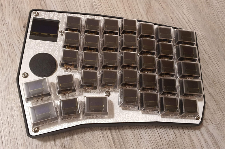
TA-DA!
Okay, so now with displays and lights on:
![]()
I didn't fix the displays indices yet and with that they don't show the correct content. However, I was so happy that it all worked out and just took a quick picture. There is some homework left for me!
Now it is time to bring the same changes to the left side and the hardware of the PolyKybd Split72 is ready!!
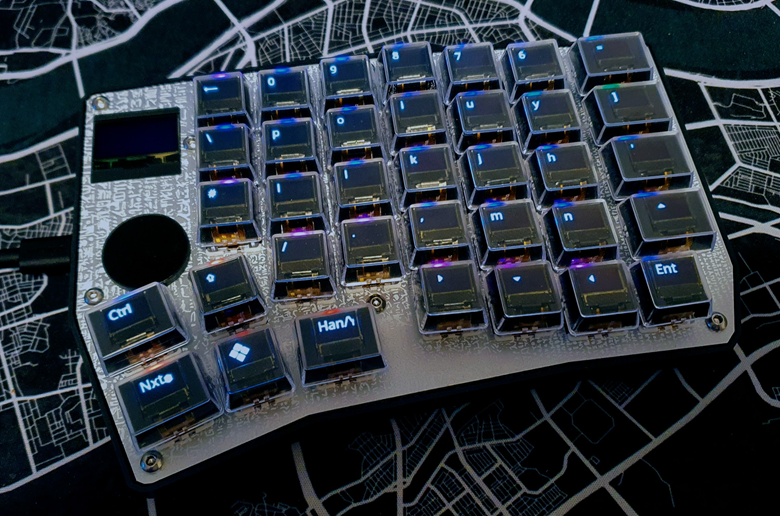
Sidenote
You might have noticed that it is really tricky to make good photos when the displays are on because those are much brighter than the environment. At some point I should maybe do some more professional HDR shots!
![]()
(until that time, I will just tweak light and contrast of my cell phone pictures)
Thanks for reading and let me know what you think about it in the comments!
-
Generate A Case With KiCad And OpenSCAD
03/28/2023 at 09:36 • 0 comments
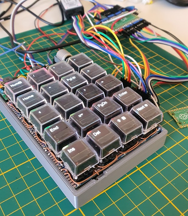
The very first case for the left side was done manually. Just like I did for my macro pad prototype - measure everything and then model a fitting case:
![]()
Well, still I had to break away some parts as you can see :-P, this process usually needs multiple iterations to really fit well.
For left side case, I had at least some automatic step, so I haven't had to measure everything: In KiCad, I exported an SVG from the PCB outline and started modelling a case around that:
![]()
That worked, but I don't want to repeat that for the right side as it is just too much manual work. Also any changes to the position of the LEDs, USB connector or the mounting holes would be a disaster!
The good part is, that I now know how the case should look like from the design standpoint!
What I also learned, is that there would be less manual modelling needed, if I placed all bottom SMD parts well within the PCB (well at least 2mm+). Then I don't need to modify the edge where the PCB sits on because of colliding parts. Obvious? Right? Seems like I had to experience that first to realize.
Next Iteration
So for the right side I wanted to start with a more generic and automated approach that ideally creates a fitting case based on the PCB alone.
To make the project as open as possible, I resisted to use any modelling software that would need a paid license. With these two ideas in mind I was wondering if I could use OpenSCAD to programmatically generate the case.
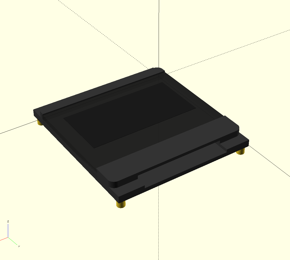
I already used OpenSCAD for the keycap stems and the display holder, why not for the case as well?
![]()
![]()
So How does it work now?
I still export the outline as SVG, however without all the cut-outs for key switches. In KiCad, you can select which layer to export and each layer can be a different SVG. So the most convenient thing is, to copy the board outline to a separate layer (since the key switch cutouts are also on that layer, but we don't need them). Then create a layer for each of the other physical features like:
1. Usb port cut-out (just a rectangle that can be extruded and subtracted)
2. LED cut-out for the status lights (just a line starting from the middle of the part perpendicular to the board outline)
3. Reset and Boot-Select switch cut-outs (again just rectangles)
4. And finally the stand-offs, which I just redraw as circles in a new layer as circles with the exact diameter of the drill hole.
So all together that makes 5 different SVGs (well, I also optionally had cut-outs for debug ports but that will not matter in the end).
All Set?
Unfortunately, my outline was not perfect (tiny gaps) and I had to fix it with InkScape to make one polygon out of it (I don't remember the exact steps, maybe there is some expert who can comment? Maybe there is a command line tool to do that?).
Apart from that, for some reason, all lines in my exported SVGs where in groups and I just got all lines out of any groups and deleted the empty groups as OpenSCAD had issues with objects in groups.
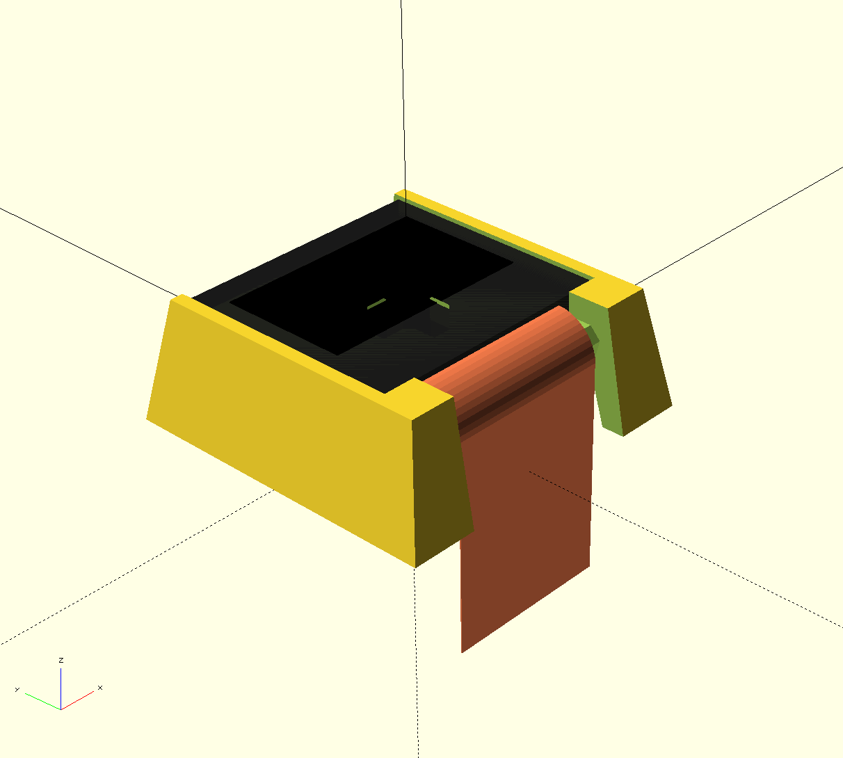
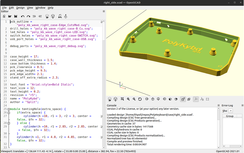
After these little cosmetic operations, I can load the generated SVGs into OpenSCAD:
![]()
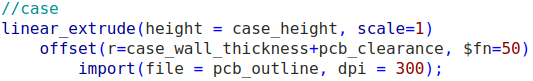
With the offset command I can make the extra space around the PCB for the case. All that missing is a linear_extrude and we already three dimensional representation:
![]()
If the outline or another physical property ever changes, I just regenerate the SVGs and run OpenSCAD again. That's all! I love that!
You can find the current version as usual on my git repo: https://github.com/thpoll83/PolyKeyboard/blob/master/case/right_side.scad
And as usual my apologies for the mess in the repo, I really need to cleanup the structure. It's just like my desk ;)
Remaining Manual Work
There are a few things that might need manual adjustment once a while, but it's really manageable:
- The logo as I just placed it loosely in the middle
- The wedge shape in the front
- The mount points for tenting (on the side)
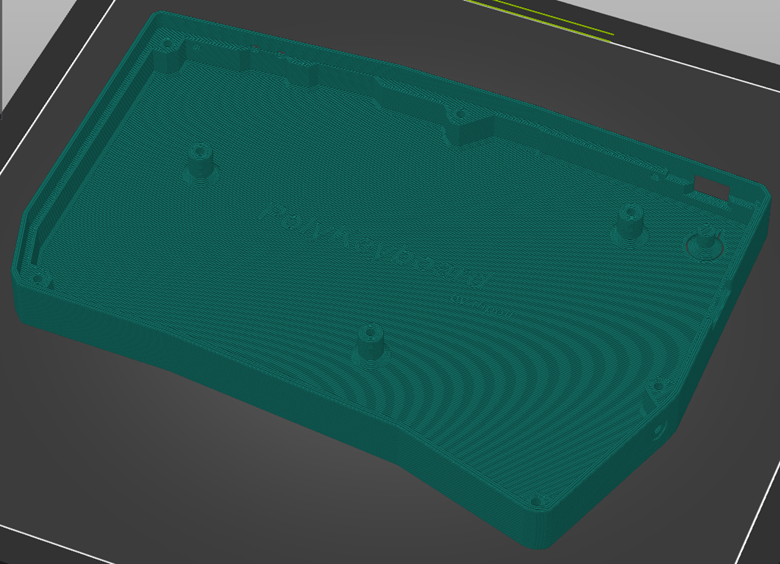
3D Printing
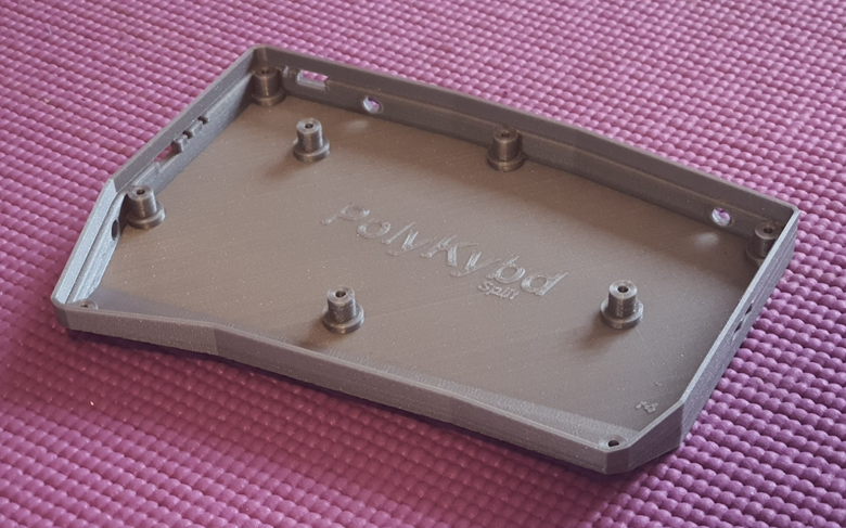
Of course I 3D printed the case and it turned out well:
![]()
I would like to show you with the new PCB, but the updated right version is currently in production and will take a few more days...
-
Success And Failure!
03/28/2023 at 09:34 • 0 comments
I had a good time designing the right side and it is really satisfying to see it turning on without any issues:
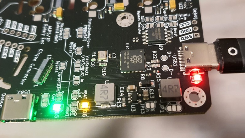
![]()
As you know from earlier posts, I used the right side to test a new hardware iteration that includes an on-board RP2040, USB-C, more flash memory, etc. So there was some risk that the board might not even boot up.
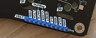
To give myself enough possibilities to tweak and debug things, I added a lot of solder jumpers and also pin headers to connect to the most important data via a logic analyzer:
![]()
Before I had to solder some wire to test points here and there just to check my SPI signals.
But the new board has a problem (makes me cry a bit), which makes it only usable as dev board and not as (Poly) keyboard. Disappointing, as all my PCBs on this project so far proved to be fully functional prototypes.
Here comes my list of what works and what doesn't.
Success:
- RP2040 with 8MB Flash and USB-C works (obviously)
- The non-inverting buffers do solve my issue with the data glitches I experienced, it was indeed a fan-out problem (😆 so happy that this is off the table)! Huge thanks to my co-worker Peter who suggested that change. This was my last electrical issue :)
As this problem was solved, it was time to increase my SPI frequency from 400kHz to 16MHz. That success made me go further so that I increased also the frequency for the shift registers to 16MHz and it works! It was a pure software change, but with the data glitches before, I didn't dare to tweak the way the shift registers operate. Finally, updating the displays is amazingly fast, no way to recognize any delay 🤯.
Now everything runs on 16MHz and I can see my 10$ logic analyzer reaching its limit. For hardware debugging I have to reduce the clock, otherwise it misses some signals (Well, I should maybe invested into a proper one... any affordable recommendations? Maybe a Kingst LA2016?).- Successfully tested the new 0.42" displays with the SSD1315 chip! These were fully compatible with the old ones having the well known SSD1306 - no change needed.
- I also consider the solder jumpers as a big success. These let me re-wire pieces of the circuit without any new iteration (like the power supply of the displays, unfortunately these really need a voltage of about 3.6V, 3.3V is not working). In the future, I will remove them as they needed quite some space on the surface though.
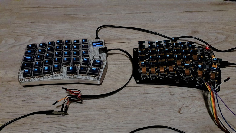
- Right and left side can currently communicate via my RJ45-to-UsbC franken-connector and you cannot damage the boards by confusing the two USB-C plugs:
![]()
If you plug the side connector into any other USB-C device it will look like an analog headphone, which is harmless.
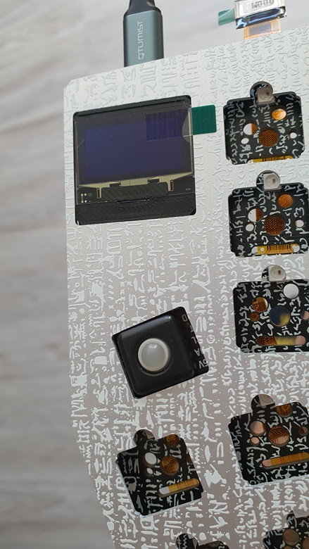
- A bit over-enthusiastic, I also decided to use an OLED status display which does not come on a break-out board to avoid any supply-chain issues with 3rd party PCBs. It's a bare OLED display with a 30 pin FPC (I2C) which I got from my trusted display supplier:
![]()
It did not turn on right away as I tied all reset lines together and the displays from the keycaps were initialized after the status OLED and so the reset triggered too late. To fix that, I now initialize them together and and we are good!
No Conclusion Yet:
- The pimoroni trackball (see picture above - fits just perfect), which can be used as alternative to the rotary encoder and is already soldered on for the current board, but I just did not configure it in QMK yet.
- There was also no time to check the cirque connector, but this will be still possible of course. It could make a nice addition or alternative to the trackball as mouse input.
Failure:
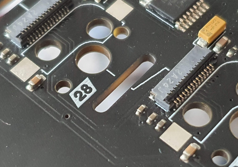
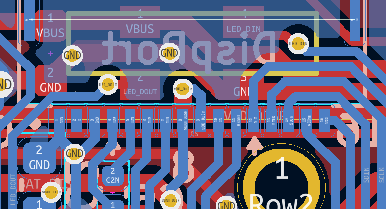
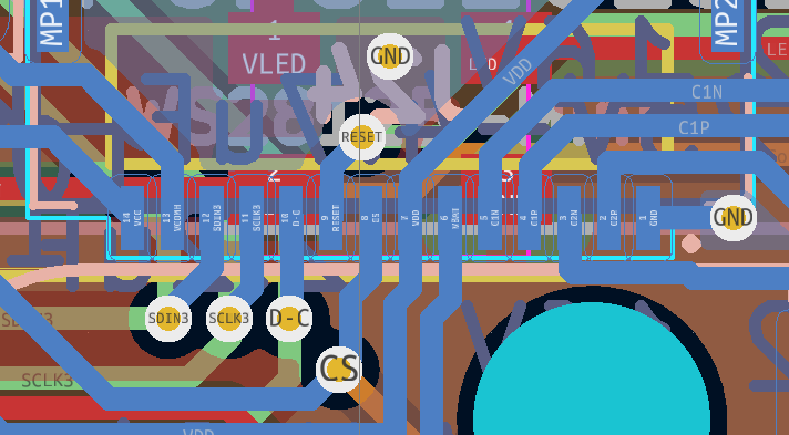
So here is the problem... Can you spot it? (new one above, old one below)
![]()
![]()
Well, it's easy if you see it right next to each other...! I changed to another FPC connector with 14 pins because the customized displays will have less pins to get rid of redundant ones (and therefore will be 1mm smaller and fit with more switches). There was even a KiCad footprint for the new socket, so I was very happy. And here is the problem... I did not compare it with the old footprint and there, pin 1 is on the right. The new one has it on the left!
Everything is electrically working, but the displays will face downward when putting them into the key cap 😭😭😭. And that means I have to make one more PCB to fix that!
What's Next?
Well, testing the trackball and getting a cirque to work and of course layout a new PCB, this time with pin 1 on the correct side!
So there will be just another iteration of the right side, hopefully already in a "final" state.
-
Organizing The Language Table
03/28/2023 at 09:31 • 0 comments
Actually, I planned to write much earlier about the language layer, but the draft never finished itself ;)
From the spreadsheet color scheme above, you can see that I support 10 languages at the moment. Of course at some point I would like to be able to download any language to the keyboard on demand maybe via the HID interface. Then, there would be no need to use a hard-coded lookup table. However, for this even more needs to be done on the software side and today I will focus on how it works at present.
Maybe the main reason why you are looking at the PolyKB is not language, but program context dependent keyboard functions? Don't worry, I think this is not too much different from the language layer. Let's call it the program or context layer, which would be just another lookup (table) to display a customized text or icon, if there is a function defined for that key. So if your focus is function and not language, please just take it as a template that can be also applied to the program context.
Easier Data Handling
Organizing the language lookup table (lang_lut) in source became an unmanable mess after 3 languages, so I started working with an xlsx spreadsheet, which indeed makes things much easier.
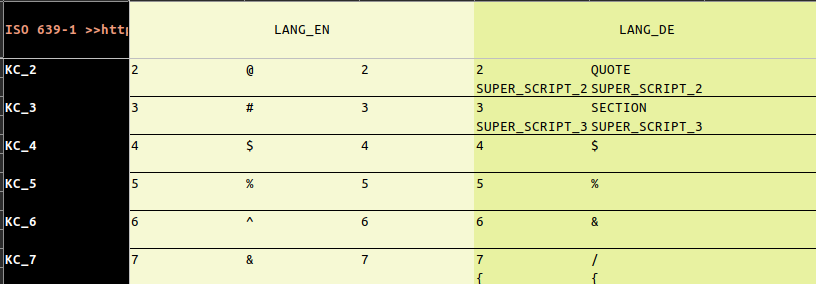
Let's look at the following example:
![]()
Each language has 3 columns. The first is what's usually displayed on the display, the second when pressing shift and the third, when caps lock is on in case it differs from the second (when pressing shift) case.
This is not uniform! For an english US layout the number keys turn back to numbers when caps lock is turned on (while the letter stay upper case of course), for a german keyboard the wild cards will stay active and behave just like the letters (and therefore there is no entry in the LUT).
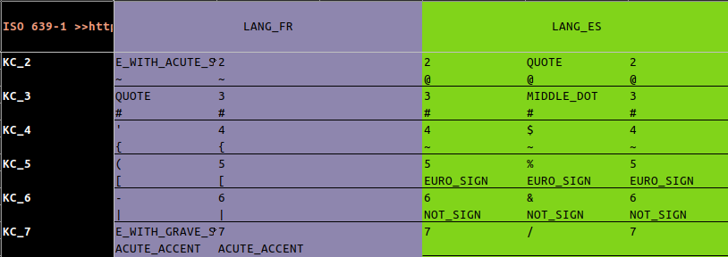
Additionally there is a second row for each key to display what the key does together with ALT (GR):
![]()
While there is nothing for the US layout, you can see that there is an additional glyph for almost every number key in case of French or Spanish.
Translate the LUT to code
To get the xlsx file into C++ source code I use cog: https://nedbatchelder.com/code/cog/
That's a way to use Python code which is inlined in C++ comments and transform marked sections with that code.
Python is quite handy here because there are libs to do almost anything (including spreadsheet data access).
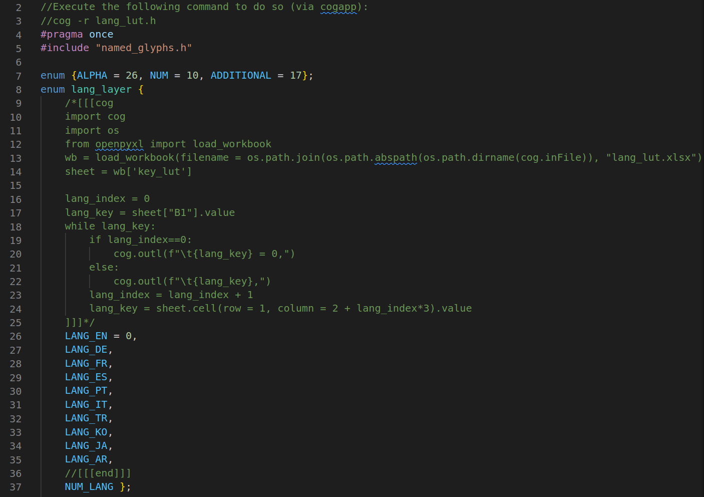
An example to get all defined languages (lang/lang_lut.h):
![]()
Everything between /*[[cog ... ]]]*/ and //[[[end]]] is generated. Just for the available languages, the effort doesn't pay off. It is an example. The python code that generates the LUT for the glyphs isn't much longer and it generates around 600 lines of code (in lang/lang_lut.c), which exactly why I use cog.
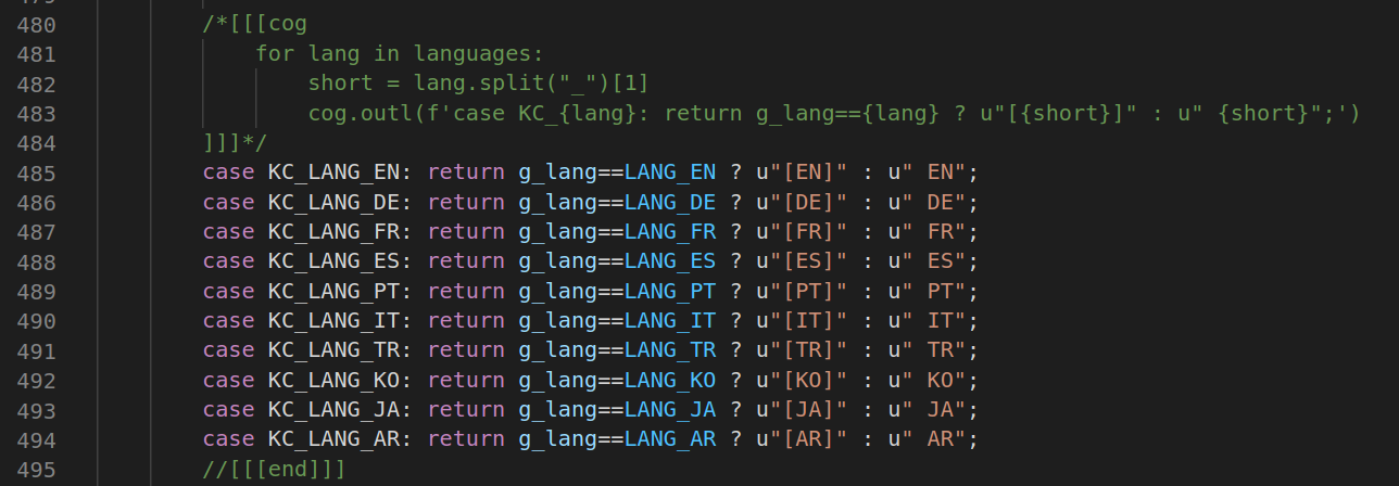
Apart from that it makes it very easy updating multiple code pieces at once. A new entry in the spreadsheet is enough and also dependent code will be updated:
![]()
That's very handy!
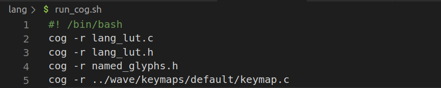
Cog needs to be executed to update the code sections and so I have a little script to run cog on all source files with Python code parts:
![]()
There is still much more work ahead to make this work in a more dynamic way, also for the program context, but let's do everything step by step!
-
More Key Switch Testing While Waiting For The Assembled Right Side
03/28/2023 at 09:29 • 3 comments
After some back-and-forth where to assemble, I finally uploaded my Gerber files at my usual go-to-shop and now waiting for the whole thing to ship in the next weeks (hopefully).
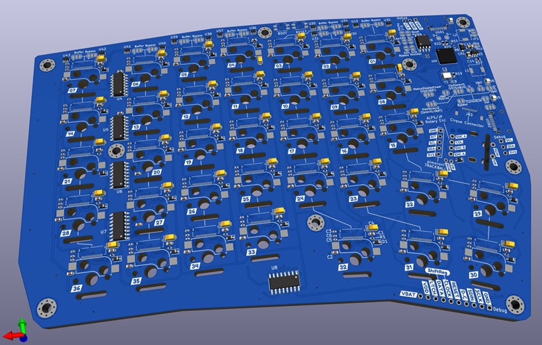
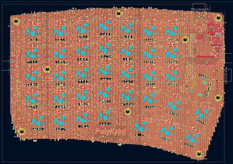
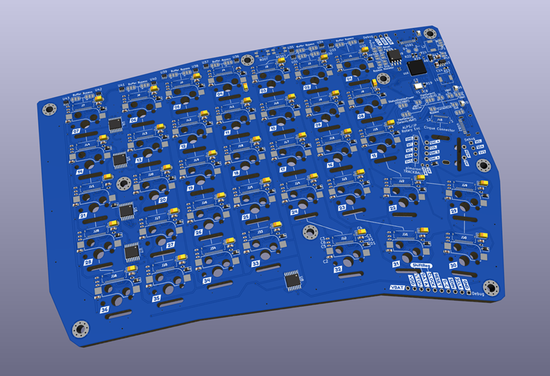
Here is a KiCad rendering how the board currently looks like:
![]()
To make good use of the time until the PCBs arrive, I decided to test some more switches.
Compatible Key switches
I'm quite happy with the results: There are now 8 key switches that work as they are, without any modification. When getting the customized displays (with a longer and smaller flex cable), this number should grow to 28 key switches!
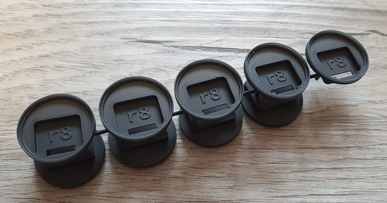
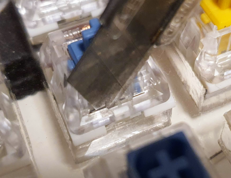
Additionally, I tested another 20 switches that work when cutting away the little bar in the middle:
![]()
I used my box cutter knife and gave it a little push on both sides and it's gone:
![]()
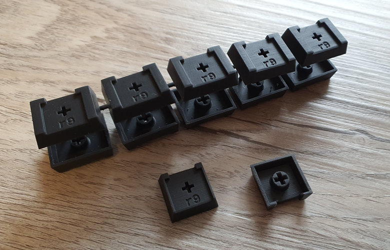
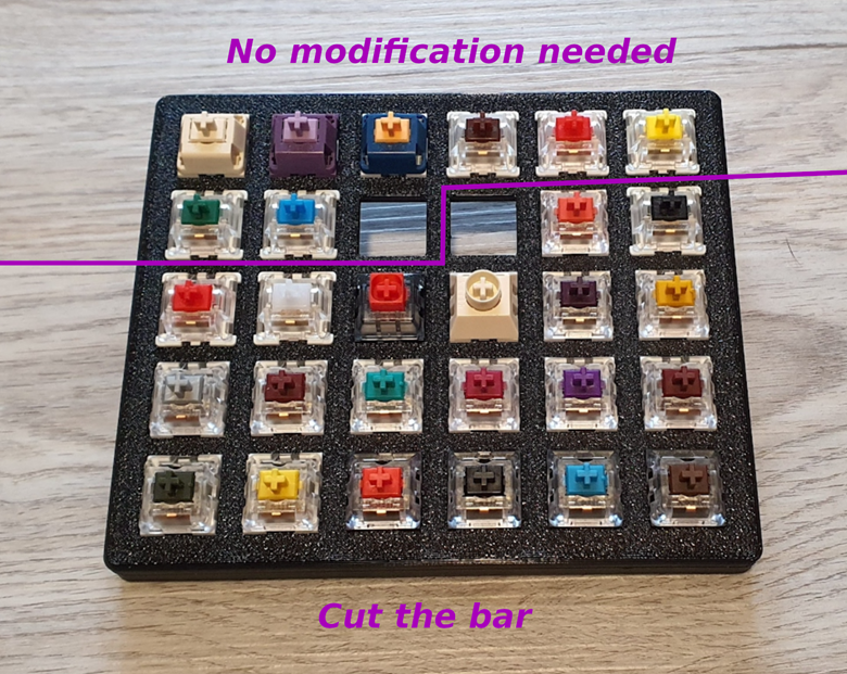
Here a picture of the happy family that can be used for the PolyKB at the moment (without any bigger effort):
![]()
And the list in more detail:
The 8 switches, that already work:
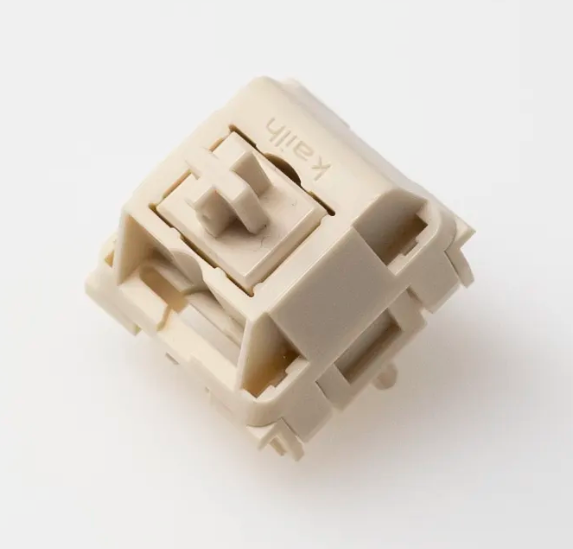
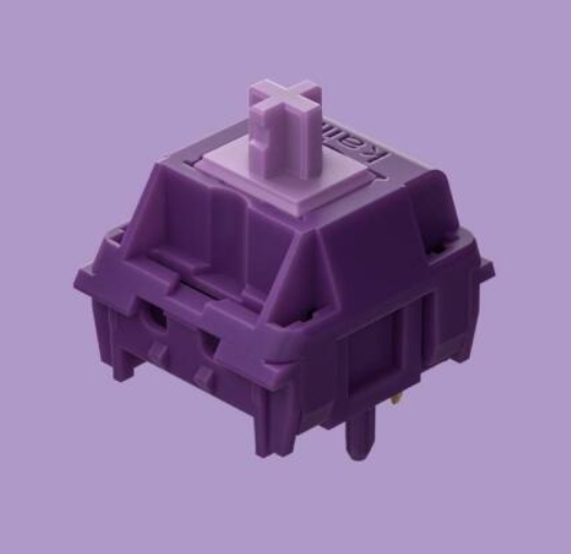
![]()
Kailh Novel Keys Cream Switch, 55g Linear
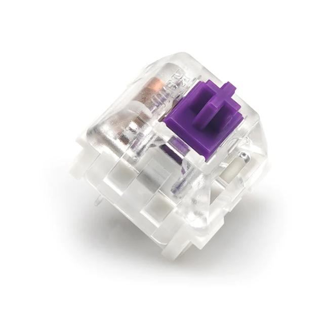
![]()
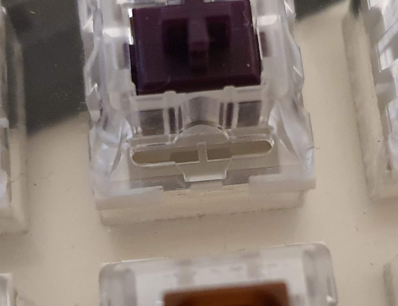
Kailh Purple Potato, 63.5g Tactile
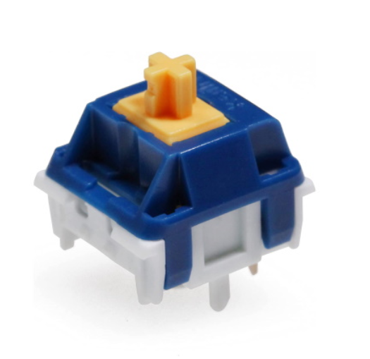
![]() Kailh x Domikey Knight Saber, 42g Tactile
Kailh x Domikey Knight Saber, 42g Tactile![]()
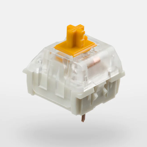
Gateron KS-9 (Pro) Red, 45g Linear Gateron KS-9 (Pro) Yellow, 50g Linear Gateron KS-9 (Pro) Green, 80g Clicky Gateron KS-9 (Pro) Blue, 60g Clicky Gateron KS-9 (Pro) Brown, 55g Tactile (they all look the same except the color)
In case you are confused with Gateron switches and their name (like me), better read this article: https://www.keebtalk.com/t/the-many-yellowses-of-gateron/17557
In short you might see KS-9 (Pro) switches with and without the plastic bar and might get the wrong version (=in case of the PolyKB that would be the version with bar), despite the product image showing no bar, because most resellers don't care about that little difference. Better directly ask the resellser about that (or just remove the bar, it's not a big deal).
The 20 switches that work when cutting the little piece of plastic away:
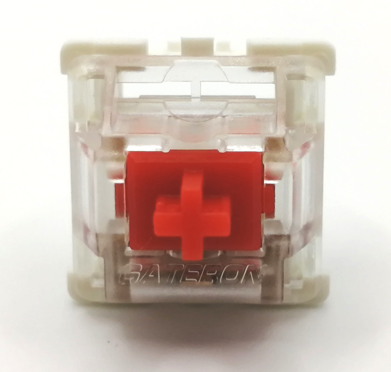
![]() Gateron KS-9 (Pro 2.0) Red, 45g Linear
Gateron KS-9 (Pro 2.0) Red, 45g Linear![]()
Gateron KS-9 (Pro 2.0) White, 35g Linear
![]()
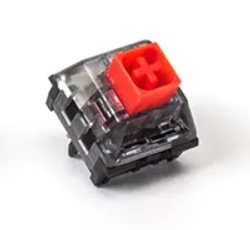
Kailh BOX V2 Red Switch, 40g Linear
![]()
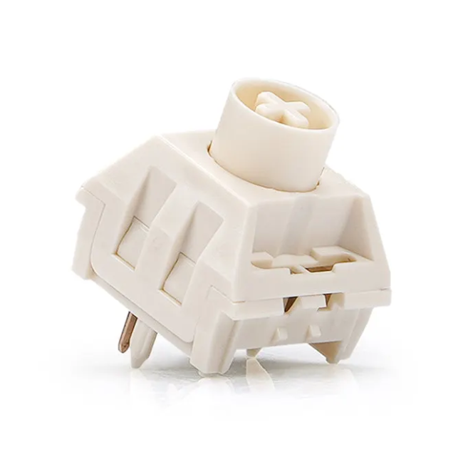
Kailh Box Cream, 45g Linear
![]()
Kailh Pro Purple, 50g Tactile Kailh Pro Burgundy, 50g Linear Kailh Pro Light Green, 50g Clicky Kailh Pro Plum, 70g Tactile
![]() Kailh Speed Gold, 50g Clicky
Kailh Speed Silver, 50g Linear
Kailh Speed Bronze, 50g Clicky
Kailh Speed Copper, 40g Tactile
Kailh Speed Burnt Orange, 70g Linear/Tactile
Kailh Speed Gold, 50g Clicky
Kailh Speed Silver, 50g Linear
Kailh Speed Bronze, 50g Clicky
Kailh Speed Copper, 40g Tactile
Kailh Speed Burnt Orange, 70g Linear/Tactile![]()
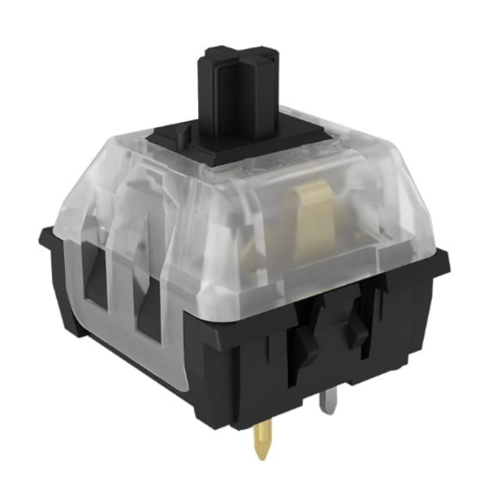
Kailh Speed Pro Heavy Army Green, 70g Clicky Kailh Speed Pro Heavy Yellow, 70g Linear
![]()
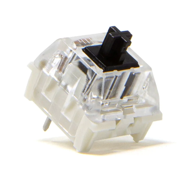
Kailh Black, 60g Linear
![]()
Kailh RGB Red, 45g Linear Kailh RGB Black, 60g Linear Kailh RGB Blue, 50g Clicky Kailh RGB Brown, 50g Tactile
Also Kailh naming is not everywhere the same (including the Kailh website), so you might find these switches under slightly different names.
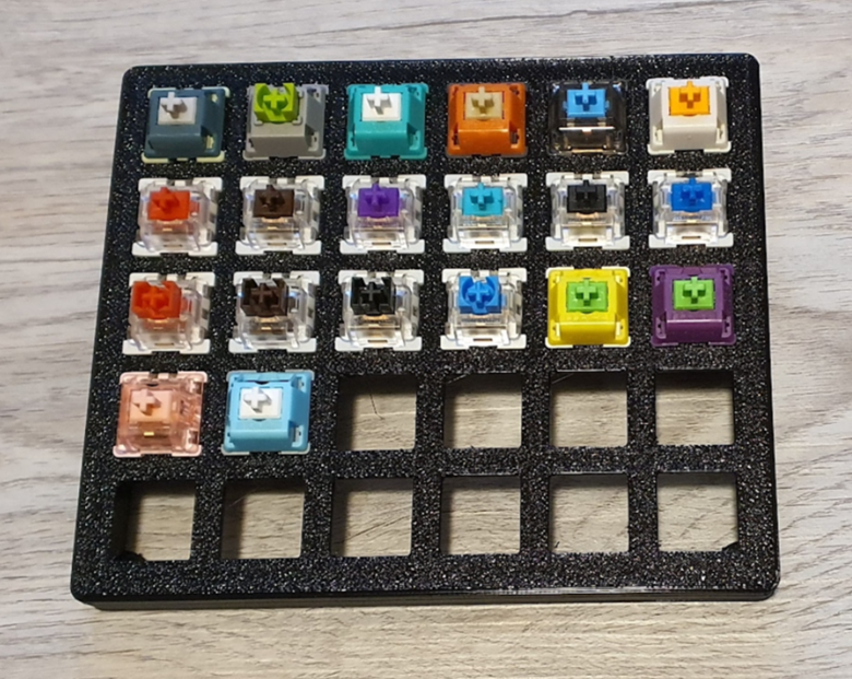
And the 20 switches I expect to work soon:
![]() From left to right, starting with row 1:
From left to right, starting with row 1:Ashkeebs Alexandrite
Owlab Neon
Aflion Tropical
Waters GOJU Works x Tecsee
Safety Switch Blue Dusk Panda (by BSun)
Glorious PandaRow 2:
Outemu Red
Outemu Brown
Outemu Purple
Outemu Teal
Outemu Black
Outemu BlueRow 3:
Outemu Dustproof Red
Outemu Dustproof Brown
Outemu Dustproof Black
Outemu Dustproof Blue
LCET Sprout
LCET JokerRow 4:
LCET Pink Queen
LCET GraceThat's it for today, I hope next time I can already give some feedback on the right side ;)
-
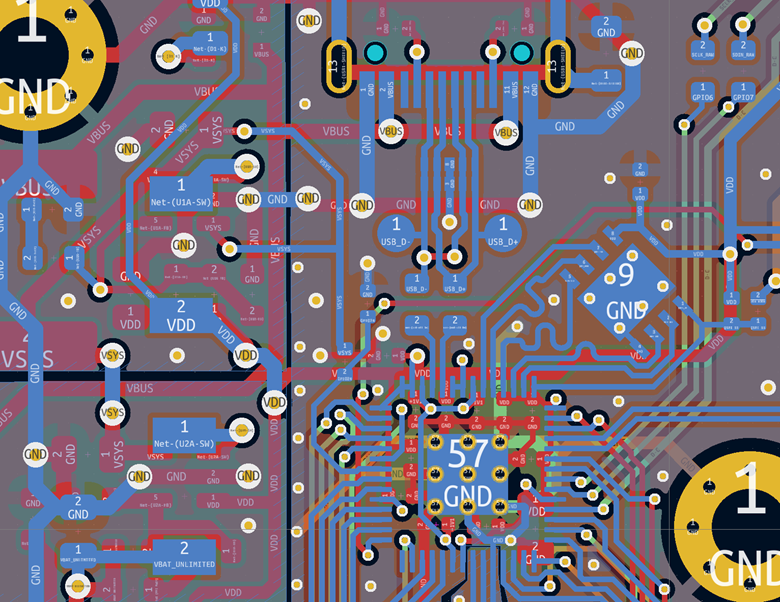
PCB Design For The Right Side
03/28/2023 at 09:24 • 0 comments
It took me some time to get started with the right side, since I had to make a couple of design decisions.
As a small spoiler, I posted a rendering on twitter (see below)
![]()
Maybe you already spotted a couple of things, but here is the complete list:
- Kailh hotswap sockets instead of Mill Max sockets (since these are a pain to solder).
- Putting the RP2040 directly on the PCB instead of using the RP2040 Pico board to 1) allow a USB-C socket, 2) access even more IO pins and 3) use a bigger flash chip as I'm not sure that the Pico's 2MB is enough in the end (paranoid?).
- USB-C for the split-link, which I decided after running a poll on Twitter and Mastodon and USB-C was the clear winner on both platforms.
- A more generic footprint for the rotary encoder which allows the a standard Alps encoder, the rotary encoder from the left side EVQWGD001, the Pimoroni Trackball and there is a also a cirque connector (for I2C)
- A non-inverting buffer for each display row on the SPI clock and data line to hopefully overcome the problem (maybe a fan-out issue of the RP2040's IO pins) I described earlier where I saw some kind of noise when updating the displays.
- Status OLED display directly connected to a socket instead of a I2C break-out board from a random Chinese manufacturer.
- I also picked smaller FPC sockets for the displays - only 14 pins - since this is the goal for the kit. And 14 pins only need an FPC of about 7.5mm which will work for much more key switches than before (which was about 8.5mm).
- Plenty of solder jumpers, which allow a lot of different operation modes. For example: I got some newer 0.42" OLED displays for testing, which allow a voltage supply of 3.3V and therefore, I could bypass the 3.8V regulator which was required for the old OLED displays.
So a lot of new stuff and I really hope (fingers crossed) it is not too much at once and the board boots up!
That's it for today. Let me know what you think about these improvements, it's not too late to change some things before assembly!
And of course I which a joyful holiday season whatever you celebrate at your home!!


 Kailh x Domikey Knight Saber, 42g Tactile
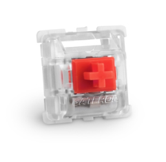
 Gateron KS-9 (Pro 2.0) Red, 45g Linear
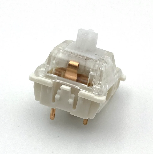
 Kailh Speed Gold, 50g Clicky
Kailh Speed Silver, 50g Linear
Kailh Speed Bronze, 50g Clicky
Kailh Speed Copper, 40g Tactile
Kailh Speed Burnt Orange, 70g Linear/Tactile
Kailh Speed Gold, 50g Clicky
Kailh Speed Silver, 50g Linear
Kailh Speed Bronze, 50g Clicky
Kailh Speed Copper, 40g Tactile
Kailh Speed Burnt Orange, 70g Linear/Tactile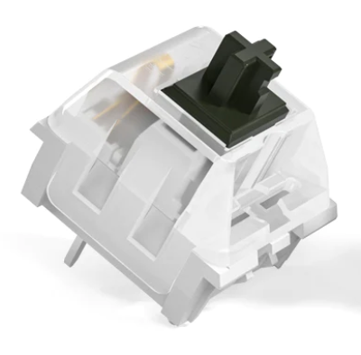
 From left to right, starting with row 1: