Close
0%
0%

ZeroPhone - a Raspberry Pi smartphone

Pi Zero-based open-source mobile phone (that you can assemble for 50$ in parts)

Public Chat
Similar projects worth following
Like this project? Subscribe here to know when it goes live! https://crimier.github.io/ZeroPhone/

This is a mobile phone that:

- First and foremost, will be a well-working reliable phone
- Is as open-source as possible *while also being cheap*
- Can be assembled and repaired independently
- Is easy to get parts for
- Doesn't have apps with privacy concerns
- Allows to write your own apps in Python

It costs about 50$ in parts, and all the parts are available on eBay/TaoBao/etc, most of the phone can be assembled with just a soldering iron. User interface is written using Python
and is being morphed into a lightweight phone-tailored UI framework.

A crowdfunded manufacturing run is expected in a month - kits will be available, as well as a small batch of fully-assembled phones. Subscribe to newsletter below!

Subscribe to the project newsletter - to get weekly news and be notified about crowdfunding!

Read previous newsletter editions

Latest newsletter editions:


  • Modern phones are getting more and more complicated and hardware-packed. Unfortunately, that means they're becoming less modifiable and repairable.
  • Phones are getting more and more integrated. Unfortunately, that means more and more possibilities for manufacturers to lock them down without allowing us to modify them.
  • More and more software&hardware is kept closed-sourced. That means it's harder to learn, experiment and customize your phone.

The factors I've listed (integration, complexity and closed-source) are necessary in the world we're living in, with all the advances in engineering, competition between companies, as well as laws in different countries.

However, what if we could have a phone free from those constraints?

So, ZeroPhone project was born. Nowadays, we should be able to assemble a phone from easily available parts, using cheap boards that run Linux, and we should be able to adjust it to our needs - unlike as it is with modern phones, when we have to adjust ourselves to suit the workflow that the phone offers. With ZeroPhone, hackers can finally have smartphones that are going to work for them and not against them, people with special needs will be able to have to have custom-tailored phones, and people that want to protect their privacy will have a phone that respects that.

Technical challenges are: developing PCBs that'd be reasonably feature-packed, but with easily sourceable components that could be soldered without special tools, as well as developing mobile phone software that'd be open, high-quality and highly modifiable to suit any needs people might have. However, much bigger challenges are - building a community of people experimenting with ZeroPhone platform, keeping ZeroPhone open-source and independent of any harmful influences, and experimenting with new ways of integrating smartphones in our lives without having to lose privacy in return.

Features:

  • Raspberry Pi Zero in a PCB sandwich
  • No proprietary connectors, hard-to-get parts or chips that are tricky to solder
  • All the specifications for making this phone yourself will be available
  • Python as the main language for developing apps (aiming to add other languages later)
  • UI toolkit that makes app development quicker and easier
  • Numeric keypad, 1.3" 128x64 monochrome OLED screen (also supports other screens)
  • 2G modem for phone functions, can be replaced with a 3G modem
  • WiFi (using an ESP8266), HDMI and audio outputs, a free full-sized USB host port and a MicroUSB port for charging
  • GPIO expansion headers for hardware addons and customization
  • RGB LED and vibromotor - for notifications

ZeroPhone Wiki

Interesting articles:

Licensing:

#pyLCI fork used for ZeroPhone is licensed under Apache License

ZeroPhone PCB files and keypad controller firmware are licensed under GPL v3


Original project...

Read more »

ZeroPhone-PCBs-gamma.zip

Latest PCB revision

Zip Archive - 12.32 MB - 10/21/2017 at 14:00

Download

  • 1 × This list is provided for the reference, for sourcing see https://wiki.zerophone.org/index.php/Sourcing_ZeroPhone_parts
  • 5 × Transistors and FETs 2x BC847B, 3x IRLML6401
  • 2 × Diodes 1x 1N4148, 1x SS14
  • 1 × ATMega328P TQFP-32 package, harvestable from an Arduino Pro Mini
  • 1 × 16MHz crystal for ATMega HC-49 or CSTCE, harvestable from an Arduino Pro Mini

View all 27 components

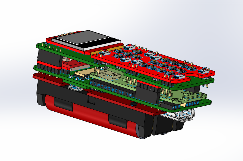
  • 3D design files now available!

    Arya12/30/2018 at 00:10 7 comments

    Hi! So, about the ZeroPhone cases.

    This is one of the most popular questions, on par with the "3G connectivity", "flat battery" and "touchscreen" ones. I'm not the kind of person that'd be good at 3D design, but, thankfully, plenty of people in this community are. During these 2 years, I had a task of making the 3D model of ZeroPhone PCBs - so that people could make a case around it. I kept putting it off, and when I did have time to work on it, it wasn't successful - one of the most important things delaying me was waiting for KiCad 5, with proper STEP support (since VRML support in CAD packages universally sucks, as I've come to understand).

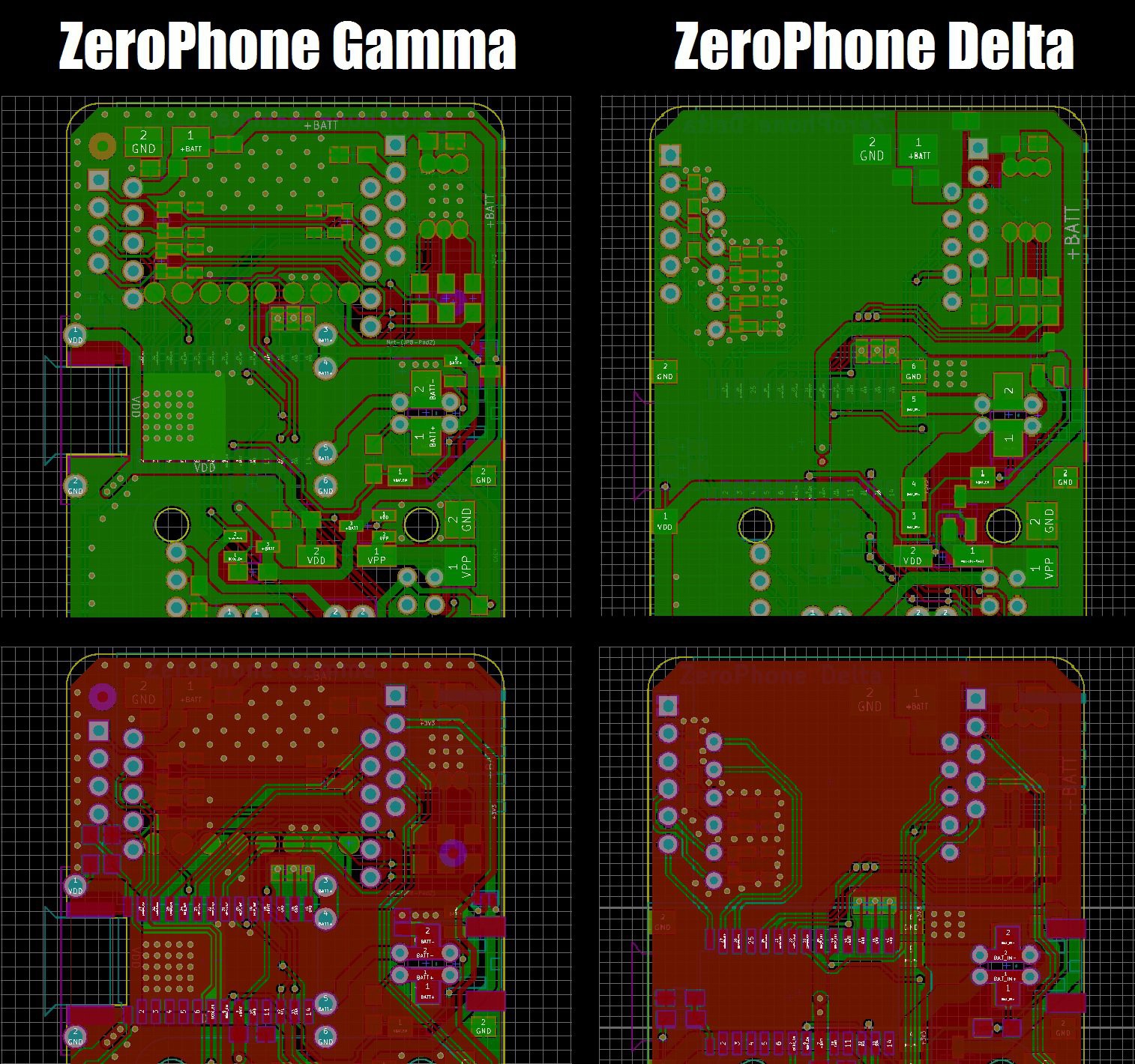
    Finally, we have a 3D model of the ZeroPhone, specifically, the Delta revision:

    It's taken a lot of work - thankfully, early in the project's beginning phase, @Dillon has helped with a lot of 3D models, designing some from scratch and sourcing others from open sources, so I'm immensely thankful for that. Current 3D model also has a lot of Grabcad material - distribution rights of which is questionable, I admit, so here's a list of all the stuff we need to replace. You can download the STEP here, and the STL here.

    Meanwhile. if you want some kind of reference design, here's a downloadable case design for ZeroPhone Gamma by @Ninjalicious  - albeit bulky, it's a viable way to make a case that actually works and holds up, one that's also snap-fit but provides all the vital openings for ZeroPhone hardware. Personally, I'm interested in some kind of lasercut design, but not for the practicality of it - I just like lasercut things =) Before the crowdfunding, if nobody steps up and designs an open-source case, I'll design one myself - to make sure we have something to offer during the crowdfunding.

    Also, I've had multiple suggestions from people, about making a ZP version in a case for a bulky phone, like the Motorola DynaTAC or this one. I can't say I'd be interested in such a case, but if I were to add, say, a FreeCalypso modem board (a 90x50mm PCB), this is exactly what I'd be looking for! With all the ways that you can expand on your ZeroPhone, I'm sure there's a lot of interesting stuff you could ram into such a phone - i.e. an expanded battery pack or a bigger screen, or maybe a Geiger counter and a high-power WiFi antenna... Why not all of that? =D


    Any information that's provided in this article may and will become outdated. Refer to the ZeroPhone Wiki page on 3D designs for the most up-to-date information.

  • Why is self-assembly important, and why use Chinese breakouts?

    Arya12/05/2018 at 16:26 1 comment

    I've been asked these questions a lot. Mostly by people who were wondering why I need to battle with and work around problems of Chinese breakouts instead of laying out all the bits and pieces on the breakout board, and why I just wouldn't put the 2G modem/charger/DC-DC on the back board, with all the benefits it would bring. There are multiple facets to these two questions - they're closely related, and I'll be answering both of them at the same time.

    Typical starting point for self-assembly on more complicated OSHW projects

    First and foremost, what does self-assembly-capability even mean for ZeroPhone? At the moment, you can assemble your own ZeroPhone independently - without any help from me, without buying parts from me or even contacting me in any way. I do provide advice in case something's unclear or there's a problem, I do sell parts, and I do link people that would like to sell some parts (i.e. PCBs) with people that would like to buy parts - but it's all optional, I publish info on assembly, there's more and more tutorials, guidelines, and videos as time goes on. This isn't really something that a lot of projects do, it requires additional effort and insight, but it's doable.

    Read more »

  • Delta-B released!

    Arya10/26/2018 at 23:59 0 comments

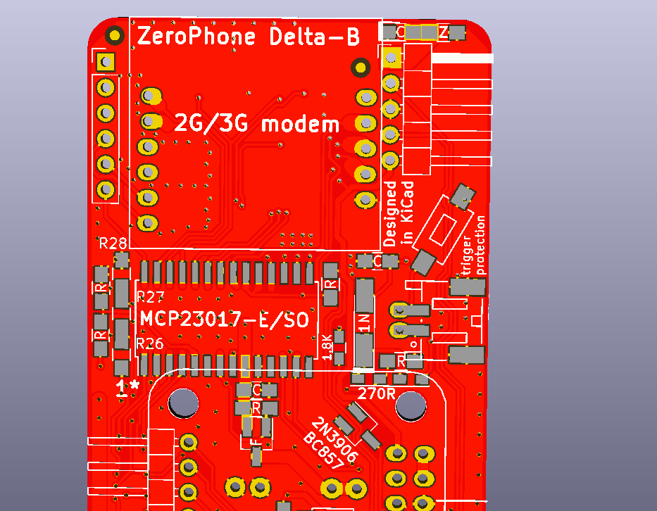
    Hi! Here's a long overdue worklog about a new revision that was released two months ago =D It's called Delta-B, the only changes from Delta are bugfixes; this time that's actually true - not like Gamma=>Delta which was planned to be like a bugfix-only revision, but had to get lots of additions.

    Read more »

  • New app - avrdude

    Arya07/01/2018 at 22:20 0 comments

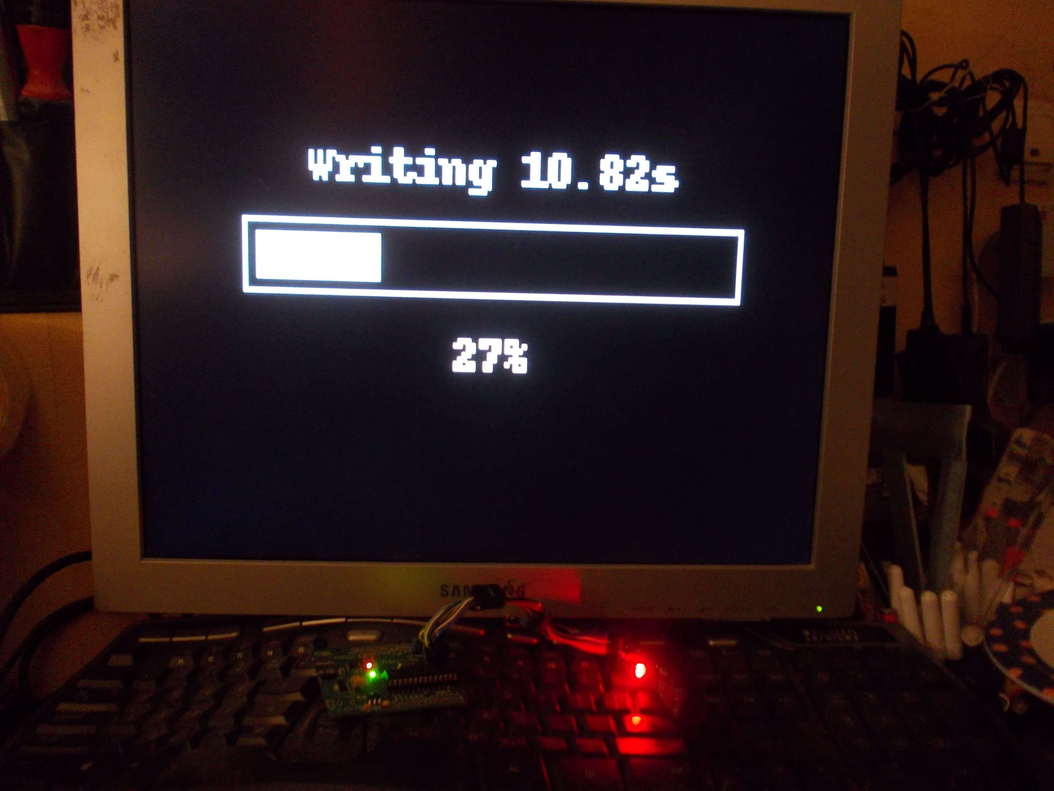
    This month, I've been working on an avrdude app - an app that uses avrdude to program AVR microcontrollers. It's now finished, with 500 LOC in the app itself and 800 more in the associated libraries. You might be surprised - why this and not something else, like a messenger app? Here are the reasons:

    • At the time, I had a small gig that involved programming 50 ATMega-based boards. So, after working with avrdude for quite a while, I was quite sick of it and wanted to automate it away - and also wanted to make sure there's a straightforward way to burn popular bootloaders to ATMega-based boards, which is a big part of this app. Now, I don't need to be summoned anywhere to program a new batch of boards - I can just give that person a ZPUI-enabled device with a user-friendly interface.
    • ZPUI needed a helper class to run long-term processes and parse their output - which is something that avrdude app would need, so after I wrote it, it only made sense to write an app around it. Such a class will be necessary for anybody who would want to write a wrapper to run any command-line tool and see what it outputs in real-time - be it ffmpeg or mjpg-streamer (which I plan to add for single-click video streaming), an interactive CLI script that needs your password, another microcontroller flasher or just a long-winded script that you want to monitor, there's now a way to wrap it in a developer-friendly object you can use to get output, send output and terminate the process at a whim (surprisingly, something that I still haven't found a proper Python library for).
    • I wanted to understand whether there's something that ZPUI lacks - it's something you can only see while you're programming a large app like this, and given that I'm the only person working on ZPUI and controlling its direction, it's crucial for me to check every once in a while if there's something that could be added to ZPUI. As a result of this work, I've added a lot of new functions, and more different ways to use the existing ones.
    • Also, I wanted to test out the recent ZPUI additions - like context switching, canvas system and class-based apps, and write a large app that uses all these things in a way that others can then refer to. While I was writing this app, I uncovered plenty of bugs and inconsistencies, which were promptly fixed.
    • Last but not least, writing large apps gives me the experience I can use to advise others on writing large apps - for now, nobody but me has this kind of experience, which is necessary to help people writing large apps that actually work.

    The end result is an Atmel MCU programming app that can backup and restore firmware from/to the MCU, flash arbitrary .hex files and bootloaders. For now, I've only tested it with usbasp programmers, but linux SPI device and other programmer support will be coming soon. I've used it a lot already, and it's even more useful given that I'm now working on several AVR-powered ZeroPhone mod boards (so, a simple way for users to update the mod board firmware is needed). It also has pinout information and the most crucial settings available, as well as some user-friendliness related features. In addition to that, there's a lot of bugfixes, improvements, new ideas for improving ZPUI and insights into problems that ZPUI has.

    One large problem that I now understand ZPUI has - lack of some kind of markup system for UI design. Essentially, when you're trying to draw your own UI, you need to calculate position of each element on the screen, requiring plenty of math (and extra variables) if you don't want parts of your UI to overlap/disappear. When it comes to text, the situation is even worse - as of now, it's pretty much impossible to properly word-wrap arbitrary text on a screen, for example. What do we do about it? I have no idea yet, and that's something I'll need to address sooner or later, unless I want ZeroPhone to be infamous for ugly apps... or not scaling further than the small display...

    Read more »

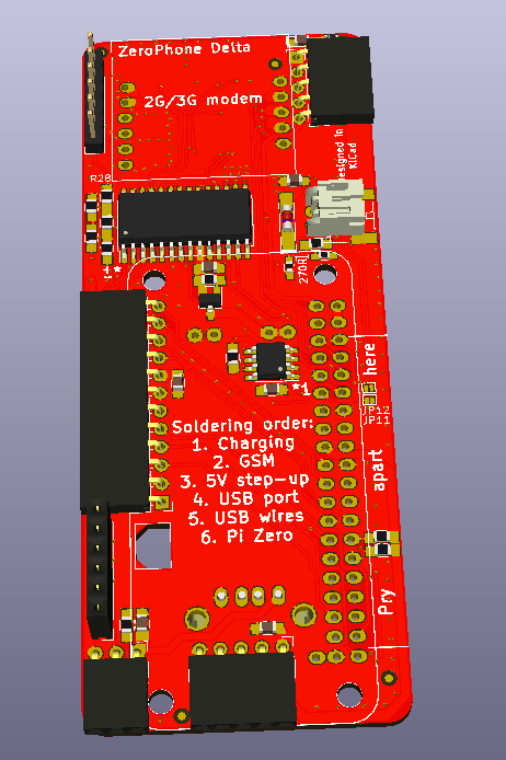
  • Delta boards released!

    Arya05/24/2018 at 00:40 2 comments

    The new revision, ZeroPhone Delta, is out. I've been using a Gamma ZeroPhone for quite some time now, and it needs some bugfixes. Specifically, I:

    • Fixed a mechanical weak spot where a row on the keypad would break due to lack of structural support
    • Fixed tantalum capacitor footprints - now they're more solderable
    • Fxed the problem where traces on the 18650 board would get exposed to the back board (and short things together) due to soldermask scraping off the back board when scratched by the back board through-hole pins
    • Flipped the 3G modem upside down, making the routing significantly easier
    • Reorganized the SPI (side) expansion header footprint, changing it to use 12-pin headers (easier to source)
    • Reorganized the I2C expansion header to be compatible with the Raspberry Pi I2C pinout, allowing to connect existing I2C RPi expansion boards to ZeroPhone
    • Reorganized the IR (top) expansion header - now it's safe to plug expansion boards in reverse
    • Audio buffer, vibromotor and keypad backlight circuits are now powered from VSYS
    • Flipped the DC-DC power FET so it's no longer necessary to solder it flipped
    • Flipped the charger board - now it's easier to solder it, as well as swap and test
    • Made the Pi Zero pads on the back board oval - making them stronger (for rework purposes)
    • Changed the 4-pin GSM audio header into a 6-pin one - for easier sourcing
    • Improved the microphone footprint on the front board
    • Made fiducials smaller - mostly I needed more space for routing
    • Improved the switchable display header - the jumper pads are now smaller, and through-hole part of it is covered by soldermask on the front of the board (to avoid displays shorting to it)
    • Made the surface-mount crystal resonator pads on the front board larger, in attempt to make the resonator hand-solderable
    • Added traces to the MCP23017 footprint in an attempt to make it more reworkable

    Here's what I added:

    • Inductors in series with GSM microphone traces - for noise filtering
    • Assembly instructions/guidelines on front, back and keypad boards
    • Usage instructions on the 18650 board
    • Expansion header pinouts on the back board
    • A comparator - detecting charger&USB undervoltage and charger board overheating
    • A circuit that'd allow sensing whether the "power switch override" button is pressed while still eping the phone switched on
    • An UART buffer - not connecting the GSM UART to the Pi UART until a GPIO is asserted
    • UART testpoints near the charger board outline - to allow for a charging+UART board to be made
    • Serial number fields on front, back and keypad boards
    • An audio amplifier for the GSM speaker (unfortunately, it's a TI part - I'll be looking for a substitute)
    • An I2C EEPROM to GPIO0 and GPIO1 to the back board - to make the back board work as a Pi HAT in software
    • Better power filtering for the GSM modem power
    • A "connect 5V DC-DC to the charger input when the DC-DC is powered off" circuit
    • 3.5mm jack audio filtering to remove GSM noise
    • ATMega UART header reverse polarity protection
    • A fuse to the 18650 board between two batteries, to avoid problems when people insert batteries in reverse, or batteries with different levels of charge
    • Finally designed the first solution to attach the GSM speaker

    I also removed a lot of things that didn't prove themselves useful:

    • The RTC footprint - proved to be unnecessary and incomplete, and was taking a lot of PCB real estate
    • The GND-BATT- jumper - wasn't useful
    • The capacitor footprint in parallel with BATT+ and BATT- - wasn't useful
    • The MPU9050-compatible footprint - wasn't useful enough compared to the PCB real estate
    • The second USB socket (facing the board center) - wasn't useful
    • The RST and TV-OUT pad connections - weren't useful (though having a way to bring them back later would be cool, maybe add a pad for a surface-mount pin header?)

    OSHPark links: 18650 board, back board, front board, keypad board and speaker adapter


    Some of these points (like silkscreen additions) could be explained further, but I'll show them off once I receive the...

    Read more »

  • Some ZeroPhone problems I'll be fixing

    Arya02/15/2018 at 09:26 7 comments

    Even though I've put a lot of work optimising ZeroPhone for everyday usage, self-assembly and manufacturing, there still are things we can do better in the next revision. Let's go through them, so that you can see the final changes I need to make to the boards, and things I need to figure out before the crowdfunding!

    This list is a result of me carrying a ZeroPhone with me through this year - and, therefore, fixing these problems will make sure your ZeroPhone lives as long as possible and is not merely some kind of gimmick that dies after a couple of months. Most of these problems are either fixable or have workarounds - if they didn't, I wouldn't have had been able to assemble the Gamma PCBs. However, they will be problematic for new people, so I have to make sure to eliminate as much of those problems as possible for the next version - to properly achieve the ZeroPhone "self-assembly" goal, making the assembly "as easy as possible" and not just "possible".

    Charging and protection boards


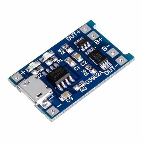
    We use popular modules from China for the ZeroPhone battery charging and protection. I had problems with the way those modules had to be soldered on the back board - it wasn't straightforward, and it wasn't easy to get done. So, I've flipped the footprint - now it's compatible with more module types, and it's much easier to solder the modules on - the board layout also became much more straightforward, since power traces used to be crossed and now they aren't! The component side of the modules is now exposed to the outside of the phone, though - I'll have to make sure this doesn't cause problems, such as short-circuits (possibly, release a 3D-printable cover).

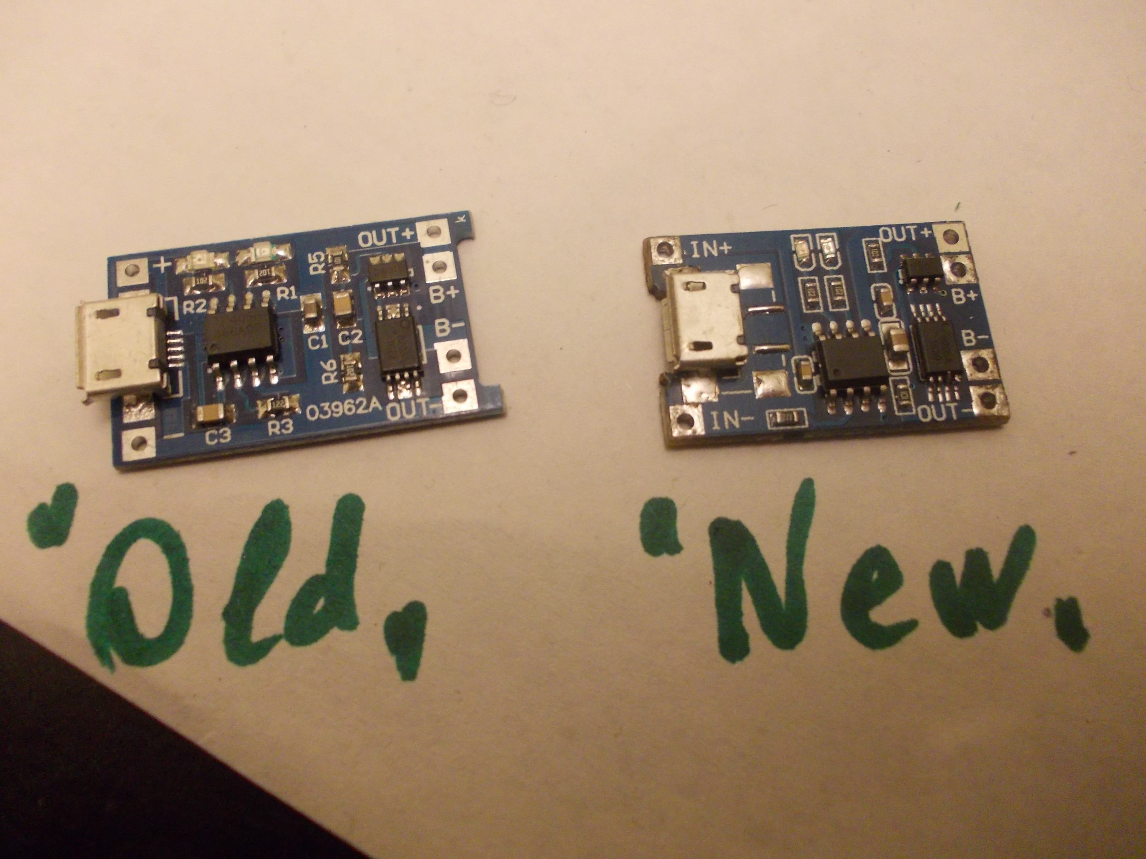
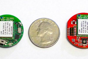
    In addition, there were stability problems with a new version of these modules. Beta boards were using an earlier version:


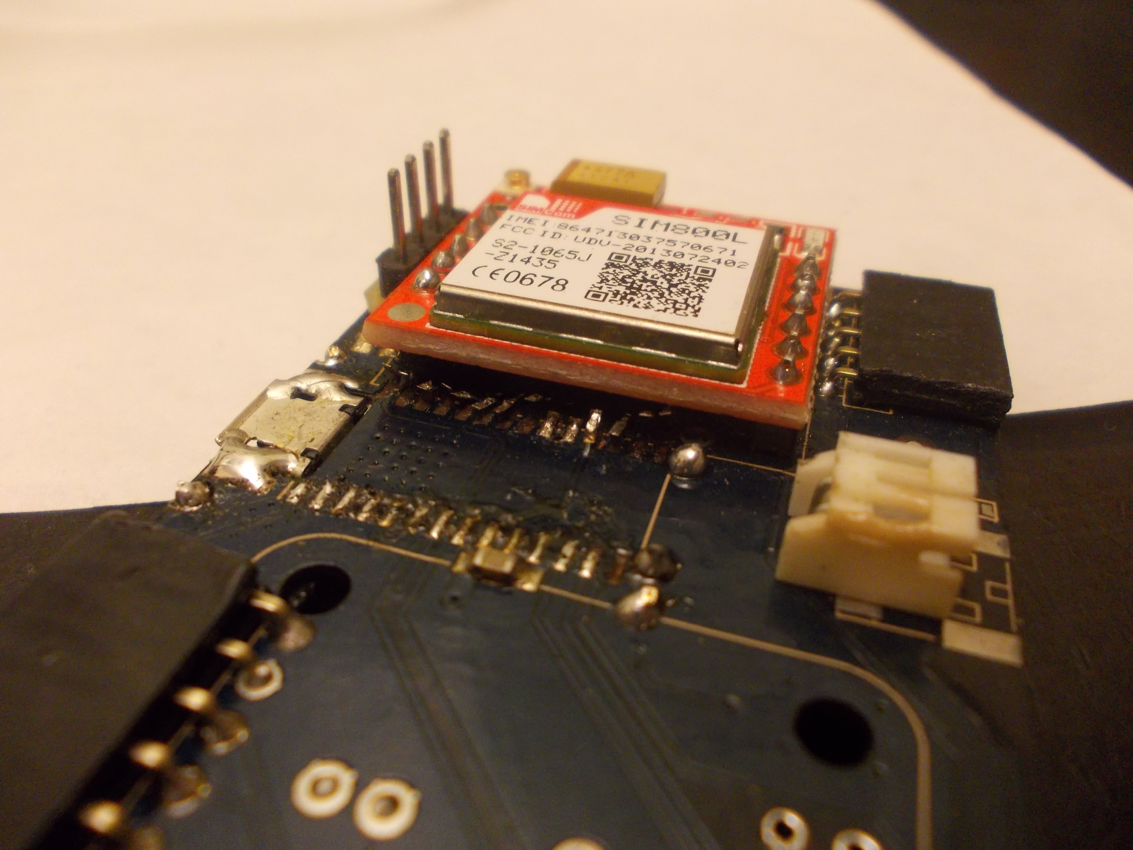
    For Gamma boards, however, I used slightly different modules, a newer version  - I ordered them by mistake, so I quickly changed the footprint to fit the new modules in order to avoid ordering the older ones. 

    That turned out to be a bad idea - the newer modules seem to not function as well as the previous, some of them randomly fail (luckily, they fail safe). It happened to some of my ZeroPhones, and it also happened to some of the ZeroPhones that I sent out (which resulted in the person having to send it back, for me to repair, and that's something I'd really like to avoid). That's not acceptable - if the module is broken, ZeroPhone cannot operate from the battery at all - or it switches off randomly, which is even more annoying. Fortunately, the new, flipped footprint allows for all kinds of modules, so it should be easier to find a suitable board now!

    During the manufacturing, we'll need to find a way to either find a reliable source for these modules, or to manufacture our own (I've already reverse-engineered the schematics and the PCB, thankfully, and I'm asking for manufacturing quotes) - as a backup plan in case the commercial modules are no longer suitable for us. I've also tried understanding the problem by comparing "old" and "new" modules - I've checked the schematic and it's the same (the boards are slightly different, but the changes are minimal), so my guess is that the "new" modules are using cheaper components, which causes the failures. But, just in case, I'm going to see if there's a way for us to source these boards reliably.
    Reworkability


    It turned out that current ZeroPhone PCBs might have some problems while doing repairs - traces breaking, pads being lifted etc. Generally, it will only happen to low-quality PCBs - but it's hard to make sure the PCBs you're ordering are of sufficiently high quality (and if you're ordering from a place like DirtyPCBs, it's likely your PCBs won't be good enough to survive overheating). This is bad, since it makes ZeroPhone less repairable - in the end, I have two back boards and one front board that are unusable because too many pads got lifted, and I also have some more that need...

    Read more »

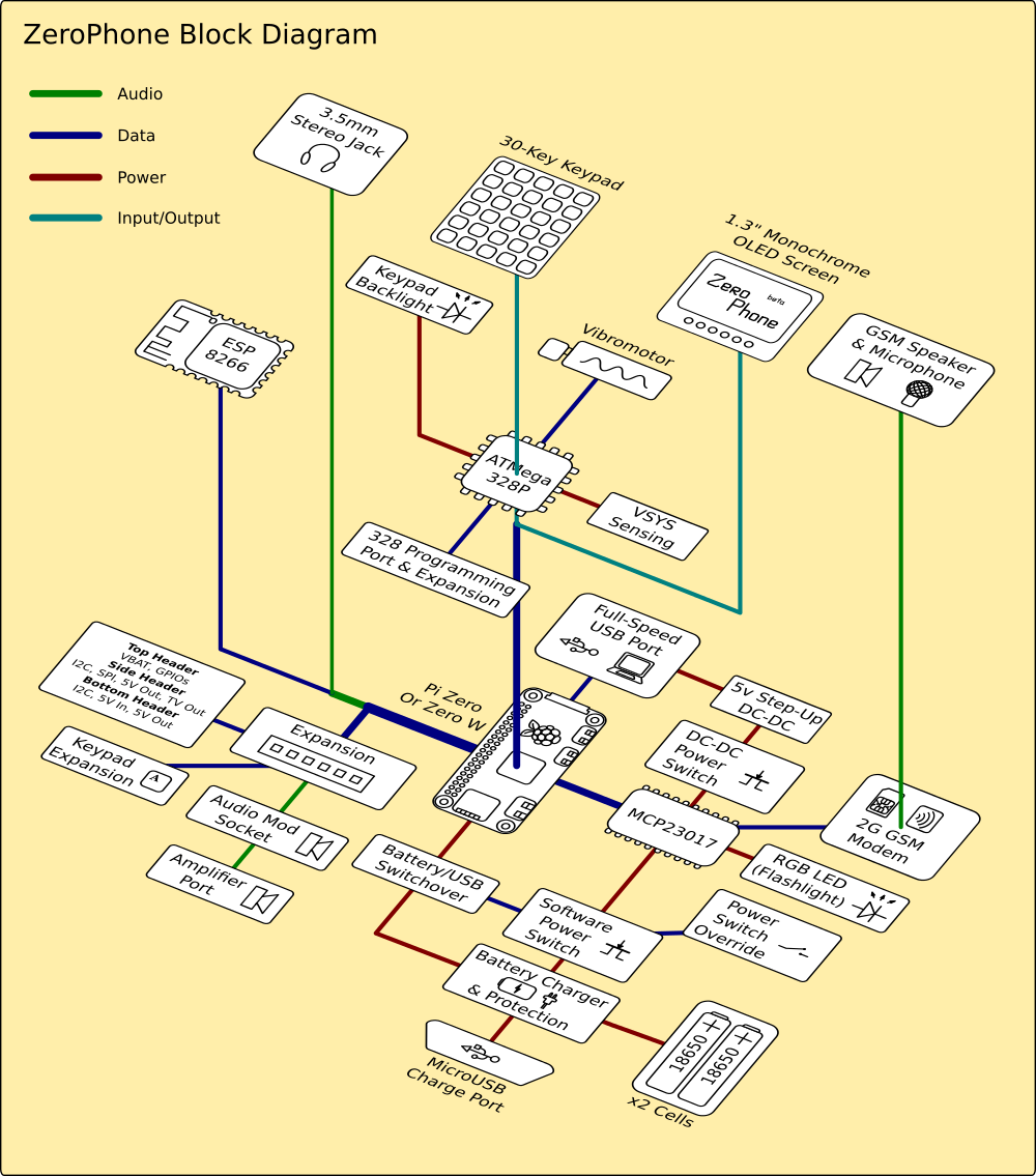
  • ZeroPhone block diagram

    Arya12/25/2017 at 11:17 2 comments

    Merry Christmas everybody! I'm going through the ZeroPhone project files, and here's something that I haven't yet posted - by @Morning.Star:

  • Writing a 2048 game for a ZeroPhone

    Arya12/10/2017 at 04:21 1 comment

    Today, I was watching my wife play 2048, and I remembered about all the fun I had with this game myself, back when it was popular. While I don't recall ever getting past 512, I did spend a lot of time and I liked it. So, ZeroPhone can fit 8 lines of text on the screen, and 2048 needs a 4x4 playing field - seems like a perfect match!

    I found some Python code on GitHub that seems to be a great fit - it's cleanly split into logic and GUI parts, and logic does not depend on the GUI in any way, so can be re-used easily. Now that's a great design, if you ask me =) Reading further into it, it seems to be somebody's programming assignment, and I have to say that it was very helpful of that person to put it on GitHub!

    So, let's reuse the logic part, and build our own UI for the game!

    Read more »

  • ZeroPhone uses: streaming audio from desktop to headphones

    Arya11/13/2017 at 06:43 0 comments

    Do you ever feel tethered to your computer because you're wearing headphones, and you can't go away from it because you can't use your speakers for whatever reason? This is for you.

    I often found myself in this situation. Sometimes I'm listening to podcasts, and I want to get up from my desk and grab something from other room, but the speakers aren't loud enough. Sometimes people around are sleeping and I don't want to wake them up, but I also can't carry my laptop with me just because I like the track I just found on YouTube. 

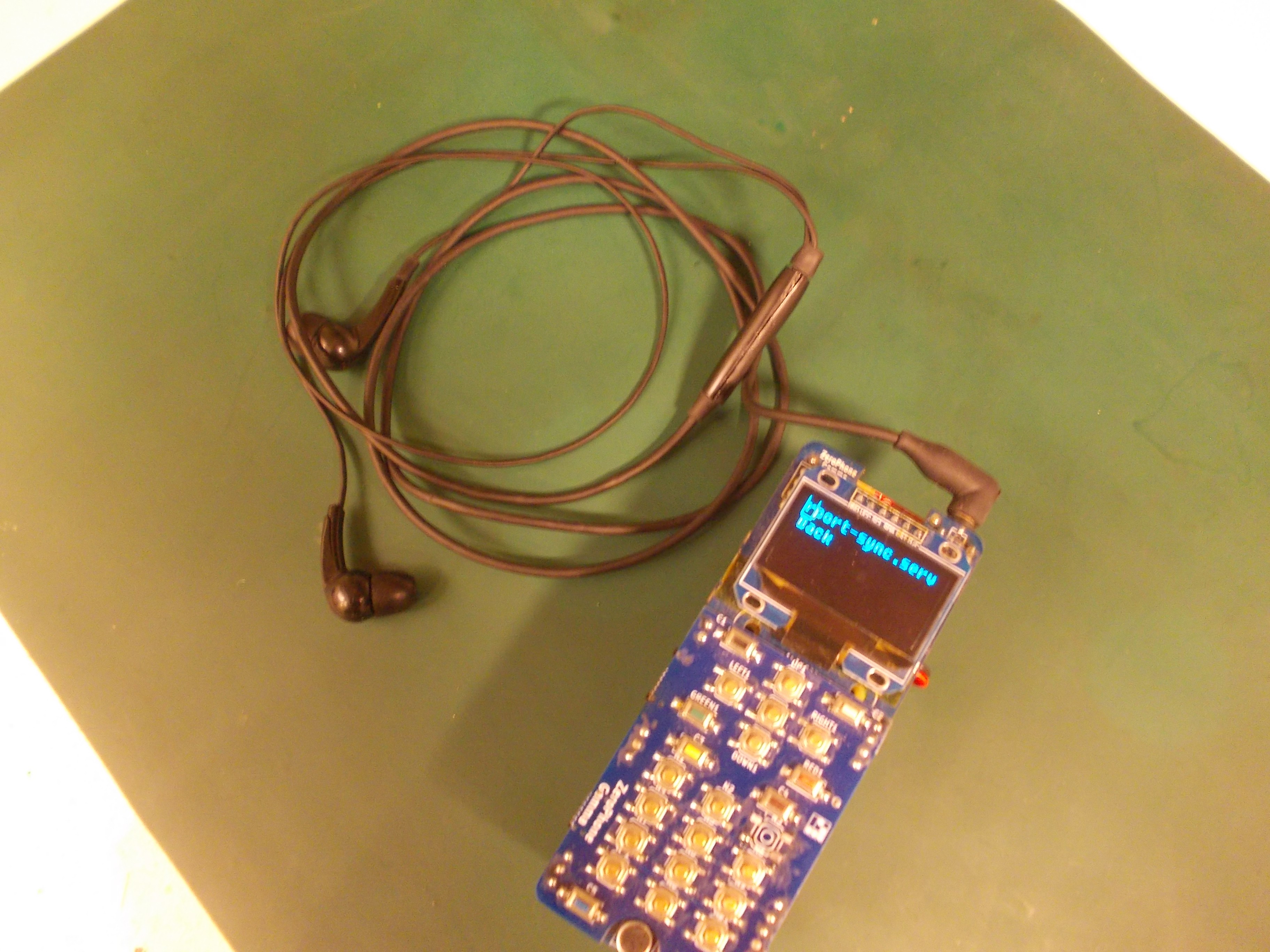
    One of ZeroPhone plans is enabling hands-free applications, using audio for things like notifications (of course, only the most important ones, and the ones you want to hear.) Naturally, I'll be using it a lot  - I'm the "headphones" kind of person, and I know there are plenty of ZeroPhone notifications I'll want to hear about immediately when they happen. Now, what if I want to listen to a podcast, should I unplug headphones from my ZeroPhone and not hear the notifications? The most obvious idea is using the ZeroPhone as an audio receiver, and stream audio from my laptop to ZeroPhone, so that notifications could be overlayed, and I wouldn't find myself re-plugging the headphones all the time.

    So, the setup is like this: I want to stream all audio from my Windows laptop to my ZeroPhone, which sits in my pocket, receives the audio stream and plays it back to my headphones. If my laptop ran Linux, I could just use pulseaudio network streaming capabilities and be done with it. As it's Windows, though, I needed to find something that would work on Windows and would be more user-friendly than using a long command-line copy-pasted from Stackoverflow.

    Read more »

  • An in-depth explanation of a simple GPIO app

    Arya11/08/2017 at 04:09 0 comments

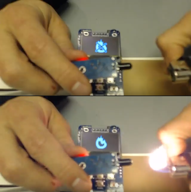
    For Hackaday Prize video, I made some simple ZPUI apps (some of them were mockups, though). One of them was reading an external flame sensor and displaying pictures on the screen depending on whether the sensor detected flame or not. I had to do this in a rush, and I ended up adding some basic, but very useful, functions to ZPUI (though I did have to clean them up quite a bit before I could merge them into official ZPUI version =) ). 

    What's the algorithm of this app?

    Set up the GPIO
    In a loop, read from the GPIO pin
    If pin has logic low on it:
        display picture of fire
    Else:
        display picture of fire crossed out

    The app is, therefore, very short. So, let's go through it thoroughly, explaining it in as much detail as possible!

    Read more »

View all 50 project logs

  • 1
    Step 1

    Instructions are under construction

    Sorry for any inconvenience =) It takes time to make them as good as I want them to be.

  • 2
    Source the PCBs

    You can use OSHPark, DirtyPCBs, Elecrow or some other PCB manufacturing service to order PCBs. Grab the latest release from GitHub, order the PCBs and wait for them to arrive! More detailed instructions are available here

  • 3
    Source the components

    The full list of components (with links to places where to source them) is still being compiled here. Meanwhile, you can use this Google doc as a reference - I'm also making my calculations for larger-scale manufacturing runs of ZeroPhones there.

View all 10 instructions

Enjoy this project?

Share

Discussions

uwr01207 wrote 06/27/2018 at 19:19 point

Can the screen be made bigger and run Android or CopperHeadOS? If no then why not?

  Are you sure? yes | no

Arya wrote 07/01/2018 at 22:28 point

Screen: not exactly. A bigger screen can be added (either through SPI or HDMI), but it can't run Android. The biggest problem is that Raspberry Pi Zero can't really run Android - and so, I've decided I'm not going to pursue it, instead focusing on Linux and making a small&sleek UI for dumbphone features (and quite some smartphone-related, too).

  Are you sure? yes | no

sworobukjamie wrote 11/20/2017 at 02:58 point

when will we get the instruction so we can make this beautiful piece of tech?

  Are you sure? yes | no

Arya wrote 11/22/2017 at 17:32 point

The instructions are being slowly compiled here: https://hackaday.io/project/19035/instructions It's a massive task, so I'm working on it in the background, adding new parts once a week. But before this is finished, I'll finish sourcing instructions - those are going to be finished much sooner =)

  Are you sure? yes | no

Jonathan Cross wrote 11/06/2017 at 18:56 point

It is great to see someone working on an Open Hardware phone, but how do we keep this from falling into obscurity like so many other projects?  Have you considered teaming up with others to collaborate? 

  Are you sure? yes | no

Arya wrote 11/10/2017 at 12:29 point

Absolutely! I'm taking it slow in this regard, I have lots of people to send prototype units to, but I'd rather fix some glaring issues (such as microphone noise). Nevertheless, I've sent out about 10 ZeroPhones to collaborators already, and I'm going to send out more (I've got one on my desk that's going to be sent out on Monday, for example). I'll also seek opportunities to collaborate with other open-source phone makers - right now, I'm looking at reusing their software. 

My general idea about "not letting the project fall into obscurity" (which is, indeed, a big problem) is making the project cheap and easy to replicate - one of the main goals of this project. Once that's achieved, we only need reliable software to go with it - and that's what I'll be putting work in, too =)

  Are you sure? yes | no

Jonathan wrote 11/02/2017 at 05:19 point

What are the possibilities of VoTor? Haha

Voice over Tor?

  Are you sure? yes | no

Arya wrote 11/10/2017 at 12:51 point

As long as there's existing software that does it, that would be easy =) Once I'll get the microphone addon board made, I'll be looking into things like these. Any existing software for voice over Tor that you could suggest?

  Are you sure? yes | no

tngreene wrote 10/06/2017 at 14:19 point

Hey, been keeping an eye on this for a while. Did I miss the crowdfunding opportunity? I'm not sure how crowdfunding works in the sector of the tech world works, but I was expecting like a Kickstarter or Indiegogo link to appear sometime. I'm new, obviously.

  Are you sure? yes | no

Tor wrote 10/07/2017 at 22:48 point

https://www.crowdsupply.com/arsenijs/zerophone   <- This is what I found for a pre-launch crowd funding page. I'm not affeliated with the core team, but I have been watching every single day for updates. I'm so excited for launch.

  Are you sure? yes | no

Arya wrote 10/11/2017 at 14:02 point

Hi! Sorry, would've answered myself this earlier but didn't get a comment notification - again =( So, I'm still preparing the hardware for the crowdfunding - there are lots of variables I need to take into account before I can even estimate the cost, and I also need to make a revision which is as optimized for independent assembly as possible - which is going to be the next revision. Also, I'm now working on complying to Hackaday Prize finalist requirements =) The pre-launch page @Tor linked is the right one, but it's taking time to get to the launch.

  Are you sure? yes | no

dinu wrote 09/09/2017 at 02:46 point

Great piece of work, thanks for sharing.

  Are you sure? yes | no

Magnus Westin wrote 09/02/2017 at 05:42 point

I tried to make a donation using your paypal link, but got this error from paypal:
This recipient accepts PayPal payments only through their website. To complete this payment, please go to their website and follow their instructions, or email the recipient for instructions.

  Are you sure? yes | no

Arya wrote 09/06/2017 at 01:23 point

The new link is paypal.me/TheZeroPhone - I'll tell about the problem that happened in one of the next newsletters =)

  Are you sure? yes | no

Arnaldo Pirrone wrote 08/11/2017 at 10:50 point

Hi, does it makes sense redesigning the modem board to use a simcomm SIM7600C module or equivalent which supports LTE? Considering that GSM/2G is being dismissed more and more and the fact that the ZeroPhone might also be a great pocket modem device (like huawei pocket modems) i'd assume yes. I don't know if it would be cost effective, though.

  Are you sure? yes | no

Arya wrote 08/13/2017 at 08:49 point

Right now, I'm trying to find time to finish the adapter board for SIM5320 that I've started =) It's 3G, and shouldn't require too much additional hardware, so that should be OK for now - 3G doesn't seem to be dismiss-able in the next couple of years.

  Are you sure? yes | no

Blecky wrote 08/09/2017 at 05:12 point

Have you considered a Nokia style case for this at all?

  Are you sure? yes | no

Arya wrote 08/13/2017 at 08:47 point

I have, just that the PCBs will definitely need to be redesigned. There's #Nokia 3210 Retro Fit Board project - I'm watching it closely, check it out, too, it's great!

  Are you sure? yes | no

Yann Guidon / YGDES wrote 08/06/2017 at 23:05 point

Description page : January 2019 ??

  Are you sure? yes | no

Arya wrote 08/13/2017 at 08:46 point

Yep - I have quite a backlog of work, and while this is a priority, it's not as important as, say, finally getting a couple of ZeroPhones assembled to be shipped =) I'm hoping to move this to ZeroPhone Wiki, eventually.

  Are you sure? yes | no

Yann Guidon / YGDES wrote 08/13/2017 at 10:16 point

I can't wait !

  Are you sure? yes | no

Mis012 wrote 08/01/2017 at 11:03 point

Hi :)
I had this idea myself, but not enough skills to pull it off.
What you did looks really cool :) This is something In would 100% implement, because it's the right way to do it (and possible with pi zero - why not take advantage of that?) : http://www.ti.com/lit/wp/sszy001/sszy001.pdf
I hope you like this idea. ^
Also, not sure how much you like your current display, but the cheapest NICE display I found on ebay is this: http://www.ebay.com/itm/1-44-Colorful-SPI-TFT-LCD-Display-ST7735-128X128-Replace-Nokia-5110-3310-LCD-Ne-/162550482786?hash=item25d8c38762:g:Cy0AAOSwXXxZOmn-
not from this seller, there were cheaper ones last time I looked. there is python code available  somewhere to use these, or fbtft (which I would use, combined with a simple C framebuffer library, you basically just make your own). The display(/driver)-specific source file I found in mainline staging, interestingly enough. The nice thing is, a lot of languages can use c libraries. It should be gpu-independent, unless you use mirroring for hardware accelaration. Hope you consider this :)

P.S disclaimer: I hate python syntax, I rather learnt C

  Are you sure? yes | no

Arya wrote 08/03/2017 at 05:11 point

Thank you for the tips! The appnote is interesting, might be a base for one of future mod boards. Those displays are nice, alright, but the breakouts are too big for the top margin of 10cm that I'm limited by - the keypad board is 6cm high, so there's 4cm for both speaker and the display, so this display doesn't quite fit =( Also, by now, there are multiple breakouts for this display, all with different pinouts - and this is a problem for me. But yeah, I'd definitely use fbtft with that display, too (yes, fbtft has now moved to the kernel). So - noted, and future revisions might use this display =)

  Are you sure? yes | no

Mis012 wrote 08/18/2017 at 10:30 point

I'm not sure if you understand what I mean, but it is supposed to be the only usb port - charging + connecting to pc + OTG. If you don't use it, you have 1 micro usb for charging, one for data (and if you use full size for data, you kill off the usb slave function, and a lot of people seem to like OTG functioning properly (unique to zero/W)). You could make a full-size usb mod board, if that's really possible with mod boards, so you don't need OTG cable. https://gist.github.com/gbaman/50b6cca61dd1c3f88f41 for reference.

I'm glad you like the display idea :)

Also, considering this form factor cannot easily use android apps, I would suggest this instead, for a little retro feel: https://retropie.org.uk/forum/topic/11441/would-you-like-to-play-nokia-j2me-games-on-retropie It should be easy to map it to the buttons on the phone (once the java part has sources available, or you can wait for a config implementation). Alternatively, you can use hex editing to change the keycodes, but it took me half a day to figure that out.

  Are you sure? yes | no

Arya wrote 08/26/2017 at 21:09 point

My decision for now is to not use the slave functionality. However, I might just add an easy-to-use addon that'll allow for it. The guideline for me is having "a standalone portable minicomputer", and in that light it totally makes sense to have a full-size USB port. So, current arrangement eliminates the need for any special cables - for example, out of the box, you can plug in a USB 3G modem, connect the phone to charger and make a hotspot (last part is not yet available in software, but I'll work on it). For OTG, simultaneous charging&USB requires a cable that has some kind of resistor between GND and ID pins, and it's much harder to find a cable that actually works (though, it seems, EOMA68 crowdfunding campaign has found a source, for example). 

Nevertheless, connecting the OTG pin from the Pi to the back board, adding a charger&boost IC and a MicroUSB socket is possible (with a small back board redesign and a small add-on board with a MicroUSB socket), I just don't feel like it's the right decision for most of ZeroPhones. Instead, for now, I'll make an (optional) mod board that'll add a USB-UART on the LiIon charger board, as suggested recently - so the charging socket will actually be a charging+console socket, somewhat of a "developer edition". BTW, will you yourself be interested in a MicroUSB ZeroPhone? If so, I'll put it in my list of "things that people might want that I'll have to keep in mind when designing PCBs".

The J2ME thing looks promising - though I don't think it'll be useful until there's a color display, but once it's there, I'm guessing it could look great =)

  Are you sure? yes | no

Mis012 wrote 08/28/2017 at 09:32 point

Hi.

I've been gifted an android phone quiet recently, so I'm not looking for new phone at the moment. If I did, I would like USB slave functionality, trough OTG or not. Of course a hardware 3-switch (data+id) for the A port would be more handy than needing an otg cable, that I can understand.

Another thing I'd love to do, would this be my project, would be an X session JUST over Miracast. Probably with XMonad or something similar, custom key shortcuts, and maybe some menu on the device display. Not sure how well it'd work with phone keyboard text typing. But it would be an amazing way of accomplishing convergence or how it's called. But it would highly depend on the usability.

Also, in my country (czech republic), the 3G infrastructure was never really built, so 4G has WAY better signal coverage..

  Are you sure? yes | no

Arya wrote 09/06/2017 at 20:00 point

Hi! I've been thinking about OTG, and it's very likely the slave mode could actually work in the current hardware configuration (no mods required), I just need a USB male-to-male cable to test it sometime soon =)

I've heard that Miracast driver support is subpar. Which is very sad, since I myself have been looking at wireless display technology and haven't yet found a decent solution. Let's see what the future brings to us!

3G: weird. Oh well, we'll certainly get a 4G modem eventually, anyway.

  Are you sure? yes | no

afshaan wrote 07/24/2017 at 08:30 point

awesome project 

i'm definitely building one for myself

  Are you sure? yes | no

GNUtoo wrote 07/23/2017 at 19:14 point
Hi,

Your project seems to be interesting as:
- As I understand it doesn't use the raspberry pi GPU or
doesn't need to as it uses an SPI display.
- It focus on a minimal and manageable set of functionalities.
- The electronics seem to be assembled in a solid way.

I've some suggestions:
-----------------------
- The Raspberry pi uses a non-free firmware to boot,
but that might be avoidable by using rpi-open-firmware[1]
and adding the missing to make it usable on your hardware.
This will enable privacy conscientious people to use it.
- Make it robust and usable for everybody that have limited
uses cases: not everybody needs a smartphone. Even a
feature phone would work fine.
Also many people would expect or wish to have something
that works out of the box (so non-technical people, or
technical people without much time would be able to use it)
and that works in a robust way(like you don't miss phone calls,
or the phone doesn't break when it rains or travels in your
pocket).
- Take advantage of the freedom if time permits:
- Make it compatible with Android applications like silence
or Jitsi on GNU/Linux to be able to encrypt calls and SMS.

Robustness suggestions:
-----------------------
- Make a case that is as reliable as the ones on common
feature-phones.
- Beware of microSD: According to Andrew 'bunnie' Huang[2]:
"Ultimately, however, every card I’ve encountered
eventually corrupts the filesystem after enough cycles,
it’s just a matter of how long."


[1]https://github.com/christinaa/rpi-open-firmware
[2]http://www.bunniestudios.com/blog/?p=2297

Denis.

  Are you sure? yes | no

Arya wrote 07/25/2017 at 04:16 point

Hi! Great points here, and I've been thinking through them already for quite some time! In a way, this does still use the GPU - it's used by Raspberry Pi in many ways, including pre-Linux bootup, framebuffer, some peripherals IIRC, so it's not as simple as that. Focusing on minimal&manageable set of functionalities is, indeed, what I'm trying to do, at least try to keep myself to it - it's hard to hold back from writing small apps for fun sometimes =) The solidness of electronics is still something I'm currently testing and improving - and it did recently go through 12 days of uptime with no problems, uptime is kind of a "high score" thing for me (but I do have to charge it every night to keep it up).

AFAIK the open-firmware is still lacking quite some peripheral support, but, yes, I've already bookmarked some interesting links about it, and I'm planning to give it a try soon. Maybe there could be a community effort to motivate the developers financially, but then, I'm not sure that the developers consider it to be something they'd be glad to get money for to work on.

Agreed on the robustness. Speaking about it, and cases, a case is going to be developed - there are quite some problems when the phone is out of the case, such as display panel's edges breaking enough to make the image on the display unreadable =( Not to mention that lint from my jeans' pockets is collecting inside the phone by now ;-{

All of the code I'm working with is free, I'm taking advantage of free&open-source software as much as possible at this point - however, I'm sure there are still non-free parts in Raspbian, and I'm not a fan of "not install non-free stuff by default if it's necessary" approach - though I understand it and am moving towards conditions where it's a choice you can make while keeping the user experience the same. Also, unfortunately, it's hard for me to imagine compatibility with Android apps - I perceive it to be quite fundamental of a task, given that ZeroPhone currently runs Raspbian, and the screen doesn't allow for that, either. I'm not saying that the compatibility would be impossible, but I'm sure it'll be tricky. and I'm not well-versed to implement that.

Having encountered SD card corruption myself, I agree. It seems we'll need a good backup app for ZeroPhone - now that gets me thinking... =)

  Are you sure? yes | no

Arya wrote 07/18/2017 at 03:40 point

Hi! So, I've been testing a ZeroPhone with a Zero W for a month now. Well, it works - I was a little afraid about DC-DC not quite capable of delivering enough juice to everything, but it does seem to work as well as it does on the Zero. The two problems are: the WiFi antenna reception is not that great (could be normal for the Zero W, could be decreased from normal due to all the metal around the antenna - I'll have to put Zero W and Zero-based ZeroPhones next to each other and check), and Bluetooth is not accessible out-of-box - I figure it's because the DT overlay I'm using to remap stable UART back to GSM is not quite enough and there are some configuration files which need changes made (I just didn't have the time to dig further). Other than that, there don't seem to be any problems =)

  Are you sure? yes | no

elvestal wrote 07/06/2017 at 11:50 point

Can we get this ones with 3G and swedish keyboard? I want 3.. no 5. To start with. Better fire up that emulator and start building a lot of great apps

  Are you sure? yes | no

Arya wrote 07/16/2017 at 17:27 point

Hi! Damn, no notifications again =( The 3G upgrade is in the works this week. As for the Swedish keyboard - I'll be looking into getting Unicode fonts on the display, then we'll be able to have all kinds of input (and localisation) languages on ZeroPhone =)
If you'll have any questions about app development (like, ways to do things, tips etc.), come to our IRC - #ZeroPhone on freenode, kiwiirc.com/client/irc.freenode.net/#ZeroPhone

  Are you sure? yes | no

elvestal wrote 07/17/2017 at 16:24 point

This is nice, I would love to get the required hardware for building 8-10 phones on our next maker-space meetup, a perfect way to spend a saturday in Sweden

  Are you sure? yes | no

Arya wrote 07/17/2017 at 23:54 point

This sounds great! It's likely going to run you about 500$ in hardware, and I can walk you through the "ordering parts" process if you'd like me to - I'd be happy to compile a "sourcing parts" page for the Wiki, at last =)

  Are you sure? yes | no

elvestal wrote 07/18/2017 at 04:26 point

Thank you that would be terrific. I hope we will be able to take it from there, otherwise I guess we'll just have to buy you a ticket. ;)

  Are you sure? yes | no

Arya wrote 07/22/2017 at 22:10 point

Sent you a PM, do check =)

  Are you sure? yes | no

Tindie wrote 06/30/2017 at 21:14 point

We'd love to see this on Tindie :)

  Are you sure? yes | no

Arya wrote 07/18/2017 at 03:43 point

Eventually, I'm going to sell it on Tindie - but this is likely going to be after the crowdfunding =)

  Are you sure? yes | no

oshpark wrote 06/24/2017 at 19:02 point

Great project!  Are there shared project pages for the boards that were made with us?  Thanks, Drew

  Are you sure? yes | no

Arya wrote 06/24/2017 at 19:13 point

Hi! Of course, that's the least I could do for you, I'm very thankful for your help when I was working on the beta version! The current version OSHPark shared links can be found in this blog post: https://hackaday.io/project/19035/log/59341 , I'll be sharing new versions upon each board release. Once I'll make a ZeroPhone Wiki page on sourcing ZeroPhone components, I'll also add the OSHPark links there.

  Are you sure? yes | no

oshpark wrote 06/24/2017 at 19:22 point

Great, thanks!

  Are you sure? yes | no

dj butansky wrote 06/22/2017 at 16:36 point

Looks great.

Since you are in the game could you give an opinion on how hard a POCSAG pager module would be to add to this?  It has been done with RTL-SDR on the N900 but an integrated and low power receiver/decoder makes it an everyday user's option to be radio silent and untracked unless we want to power up the modem and connect to the mobile phone network.  I discussed this with RMS and he would consider finally acquiring a FOSS mobile phone like this if it respected the user's privacy rather than the power of the state and profitability of the mobile network company.

  Are you sure? yes | no

Arya wrote 06/24/2017 at 10:10 point

Hi! Do you have some specific POGSAC module in mind? It seems some of them use RS232, and we could definitely communicate over that. BTW, I even have 3 or 4 Motorola pagers in my collection of old tech - though when pagers were all the rage, I was too young to have one =) Do you have some info on the RTL-SDR&N900 usage? (seems like it's receive-only)

I think that RMS would be not pleased by the fact that there's still proprietary firmware on the Pi Zero, basically, the whole GPU-that-launches-CPU thing. Once we have a BeagleBone CPU module, however, I think it'll be OK =)

  Are you sure? yes | no

dj butansky wrote 06/24/2017 at 17:48 point

I am a N900 user still, so obviously not as pure as our prophet.  The RTL-SDR used the regular Linux SDR tools and a customized UI gqrx, I dont recall the decoder for pagers, Morse, etc; but the RTL TV dongle literally ran hot in the fragile USB port, not feasible because of the wasted electricity.  I dont have any pagers anymore in my junk collection but yes when talking to Joerg from the opemnoko/GDC project about a radio-silent but listening pager mode; so he came up with the hacker buss during the design phase for the Neo900, a GTA-4mod for the N900 form factor.  The hacker-buss POCSAG module was never actually designed that I know of but he spoke of there still being RS232 interface easy to PCB hardware around.

  Are you sure? yes | no

Arya wrote 06/24/2017 at 19:24 point

The RTL-SDR kind of decoding has to use lots of CPU power, too, so the RTL-SDR wouldn't be the only thing running hot.

Check this out: http://www.radiocom.co.uk/Radiocom - Products.htm This is literally the first result when searching for "POGSAC module", and I can't find the price but the hardware seems OK. Any info on this?

Also, how do you test the module? Are there still pager networks in some countries? Because I think Latvia has long abandoned the thing - but I can re-check if necessary.

Haven't received a notification about your comment, weird =(

  Are you sure? yes | no

Arya wrote 07/22/2017 at 22:11 point

Hi! So, any POGSAC info? I'm trying to understand what the testing setup will look like.

  Are you sure? yes | no

dj butansky wrote 07/23/2017 at 07:40 point

For power savings POCSAG pagers use an IC, I played with RTL-SDR but that is like trying to power a hotplate from a USB port.  

FM RX IC->decoder IC->serial out to ???.  
Sadly I do not know the best packaged silicon solutions to suggest to you but below are two good primers on the whole system with amateur radio DIY paging network from start to finish.

http://www.qsl.net/n9zia/wireless/pager/

http://www.qsl.net/n9zia/wireless/pager/Pager_Handbook_for_the_Radio_Amateur.pdf

if you are an IEEE this should have the design info, I cant read the whole thing though, no login.

http://ieeexplore.ieee.org/document/666002/?reload=true

here is an example decoder IC datasheet, just add a radio rx IC.

http://pdf.datasheetcatalog.com/datasheet/philips/PCF5001T.pdf

Sadly most info for hacking is for use with RTL-SDR our cheap unexpected RF deus ex machina.
But RTL dongles burn furious power vs a dedicated IC.
I remember getting a month out of my Motorola numeric pager in the 90s, it might be easiest to hot air harvest components from a old pager or cut some traces and patch the PCB to a breadboard, read the datasheets, and plug into the serial lines since you seem to have mastered SM PCB awesomeness.
I can look further for datasheets etc, just let me know; remembering I am a kludge of a hack who only really has the powers of soldering, reading English, and perhaps a principled paranoia against technology enabling a tracking society.

  Are you sure? yes | no

gir wrote 06/20/2017 at 22:13 point

congrats! I'm _so_ looking forward for this project getting finalized! Arsenijs - you earned your 1k$!

  Are you sure? yes | no

Arya wrote 06/24/2017 at 10:02 point

Thank you! I hope that you'll continue to make great stuff and inspire others by your great projects, too! =)

  Are you sure? yes | no

Youlian Troyanov wrote 05/31/2017 at 14:40 point

how long until it's on crowd supply? also could you make it maximally modular? i would like to use parts of your design with a completely different arm board, for example, an allwinner one, like chip. using a different arm board could make the whole thing significantly cheaper.

  Are you sure? yes | no

Arya wrote 06/24/2017 at 10:00 point

Sorry, for some reason I didn't get an email notification about your comment =( I'm still delayed by the prototype batch, but now I'm building a testing jig to test the parts - then, after fixing all issues found during testing and sending the phones out, the campaign can start =) 

Currently, modularity is more of a side effect, but, due to the fact ZeroPhone consists of separate PCBs, it's indeed possible to re-use them and replace them - for example, you could swap in a different keypad board. However, the processor board is to be stacked with the front and back boards in the current configurations, so unless you want to re-design the front and back boards, you'll need to design a new CPU board with the same pinout and more or less the same form factor as the Pi Zero does. Oh, and you definitely could re-use the schematics =)

I'm curious - which boards do you want to use? I'll be planning for some compatibility with other boards in the next ZeroPhone versions, so knowing about what you want to use would be very helpful because I could plan it in in earlier stages and maybe figure out some problems I wouldn't figure out otherwise,

  Are you sure? yes | no

Similar Projects

Does this project spark your interest?

Become a member to follow this project and never miss any updates