Arya
Arya-
3D design files now available!
12/30/2018 at 00:10 • 7 commentsHi! So, about the ZeroPhone cases.
This is one of the most popular questions, on par with the "3G connectivity", "flat battery" and "touchscreen" ones. I'm not the kind of person that'd be good at 3D design, but, thankfully, plenty of people in this community are. During these 2 years, I had a task of making the 3D model of ZeroPhone PCBs - so that people could make a case around it. I kept putting it off, and when I did have time to work on it, it wasn't successful - one of the most important things delaying me was waiting for KiCad 5, with proper STEP support (since VRML support in CAD packages universally sucks, as I've come to understand).
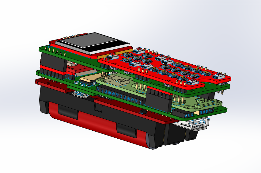
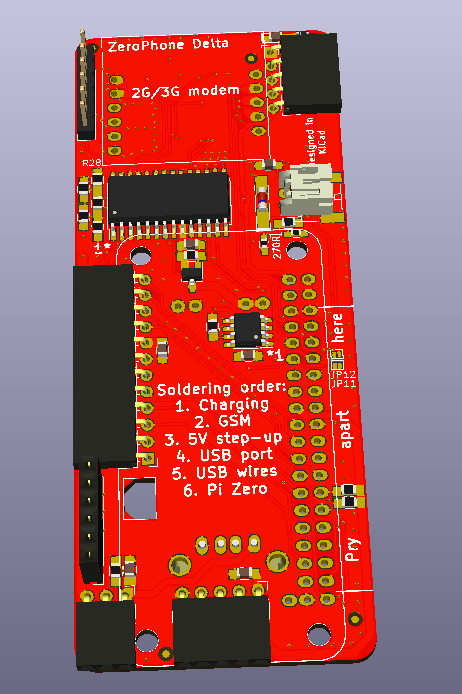
Finally, we have a 3D model of the ZeroPhone, specifically, the Delta revision:
![]()
It's taken a lot of work - thankfully, early in the project's beginning phase, @Dillon has helped with a lot of 3D models, designing some from scratch and sourcing others from open sources, so I'm immensely thankful for that. Current 3D model also has a lot of Grabcad material - distribution rights of which is questionable, I admit, so here's a list of all the stuff we need to replace. You can download the STEP here, and the STL here.
Meanwhile. if you want some kind of reference design, here's a downloadable case design for ZeroPhone Gamma by @Ninjalicious - albeit bulky, it's a viable way to make a case that actually works and holds up, one that's also snap-fit but provides all the vital openings for ZeroPhone hardware. Personally, I'm interested in some kind of lasercut design, but not for the practicality of it - I just like lasercut things =) Before the crowdfunding, if nobody steps up and designs an open-source case, I'll design one myself - to make sure we have something to offer during the crowdfunding.
Also, I've had multiple suggestions from people, about making a ZP version in a case for a bulky phone, like the Motorola DynaTAC or this one. I can't say I'd be interested in such a case, but if I were to add, say, a FreeCalypso modem board (a 90x50mm PCB), this is exactly what I'd be looking for! With all the ways that you can expand on your ZeroPhone, I'm sure there's a lot of interesting stuff you could ram into such a phone - i.e. an expanded battery pack or a bigger screen, or maybe a Geiger counter and a high-power WiFi antenna... Why not all of that? =D
Any information that's provided in this article may and will become outdated. Refer to the ZeroPhone Wiki page on 3D designs for the most up-to-date information.
-
Why is self-assembly important, and why use Chinese breakouts?
12/05/2018 at 16:26 • 1 commentI've been asked these questions a lot. Mostly by people who were wondering why I need to battle with and work around problems of Chinese breakouts instead of laying out all the bits and pieces on the breakout board, and why I just wouldn't put the 2G modem/charger/DC-DC on the back board, with all the benefits it would bring. There are multiple facets to these two questions - they're closely related, and I'll be answering both of them at the same time.
![]()
Typical starting point for self-assembly on more complicated OSHW projects
First and foremost, what does self-assembly-capability even mean for ZeroPhone? At the moment, you can assemble your own ZeroPhone independently - without any help from me, without buying parts from me or even contacting me in any way. I do provide advice in case something's unclear or there's a problem, I do sell parts, and I do link people that would like to sell some parts (i.e. PCBs) with people that would like to buy parts - but it's all optional, I publish info on assembly, there's more and more tutorials, guidelines, and videos as time goes on. This isn't really something that a lot of projects do, it requires additional effort and insight, but it's doable.
---------- more ----------![]() assembly.zerophone.org - makes SMD assembly that much more easier
assembly.zerophone.org - makes SMD assembly that much more easierIn order to make self-assembly easy, I've picked all the SMD parts so that they're easy to solder to the PCBs using just a soldering iron - as opposed to, say, hot air or oven reflow. Specifically, I've decided on using >=0.8mm pitch SMD ICs and 0805/0603 resistors. For parts that are harder to solder (or source separately), I've used breakouts where possible - SIM800 modem, 1.3" screen (with a tricky FPC cable) and the charging+protection board are all examples of that. I've also did my best to avoid picking parts that are hard to source on eBay and the like. There's only one part that violates both of these guidelines, and that's the TPA2005 - it's harder to source (not always available on eBay) and has 0.5mm pitch, it's only there because I couldn't find any other appropriate amplifier for the GSM speaker which desperately needed some amplification (to work around the fact that the breakout wasn't designed the smart way).
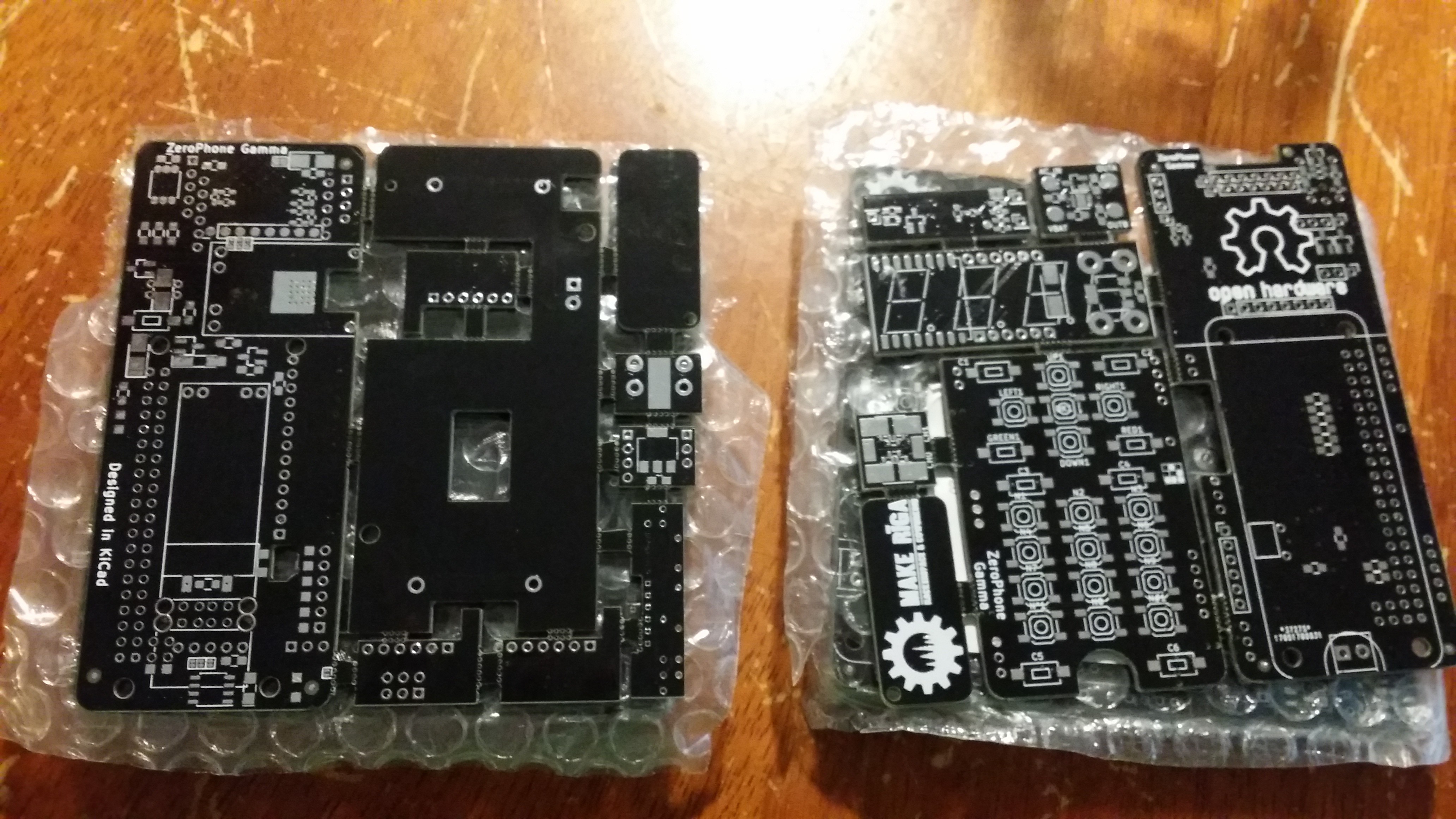
![]()
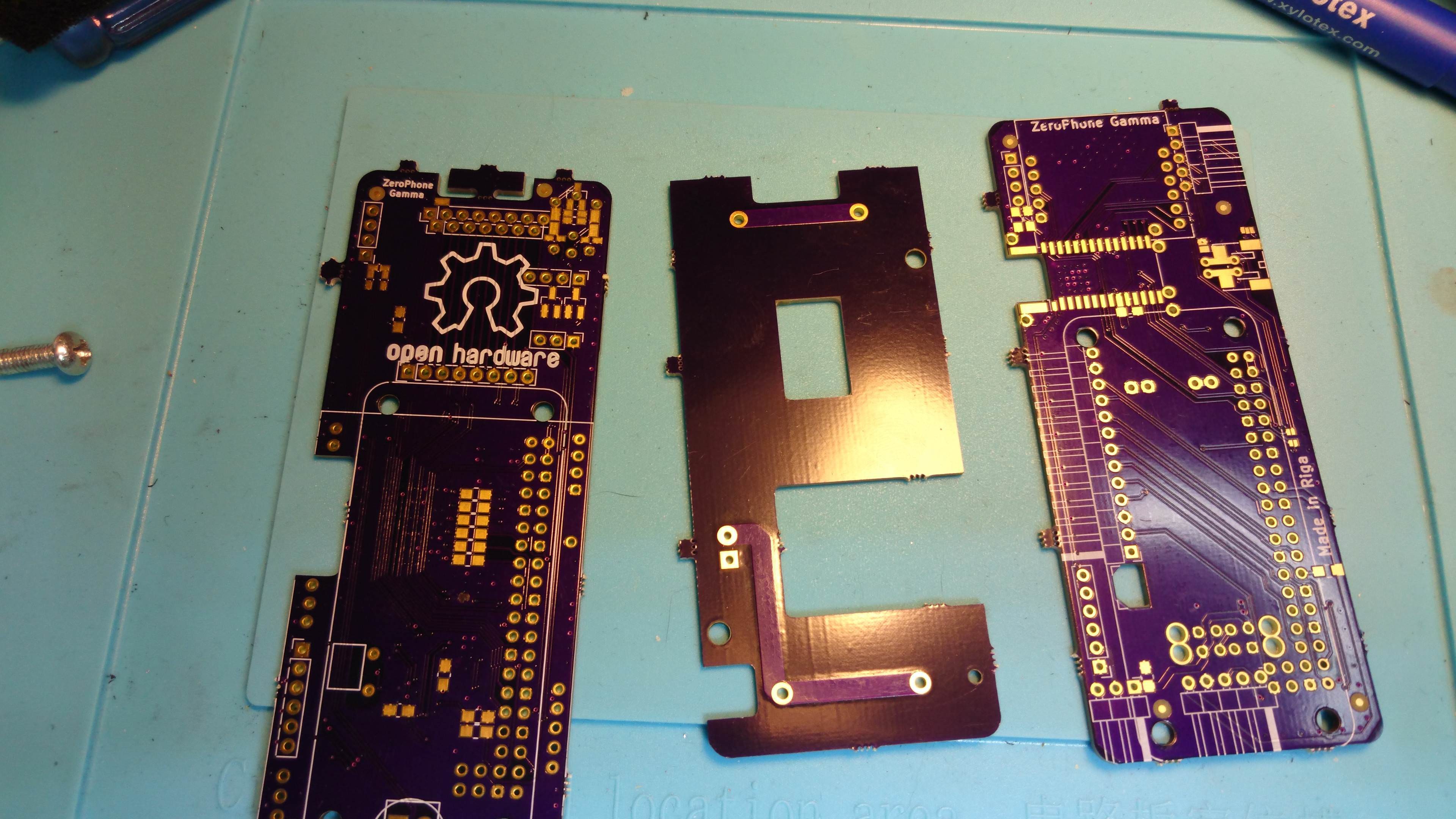
Gamma PCBs that were ordered independently last year
Was the self-assembly capability ever used? Yes, especially after Delta was released - by then, I was sure enough in the hardware and have had compiled a lot of helper materials about it, so I started encouraging people to assemble their own phones (having been more careful about that before). I know of 3 people that assembled their own phones fully (one I've sent parts to, but two others did it on their own), there are 2 or 3 more people that started assembly but haven't finished so far, and 2 more are now sourcing the parts. I'm hoping that, once I publish more detailed SMD assembly instructions (and, consequently, encourage people even more), we'll have even more people assembling their own phones - I like the joy and experience that it seems to bring to people, and I hope it can help more people advance their electronics skills. That is not to take away from the crowdfunded ZeroPhone batch, but to give opportunities for people that want to assemble a ZP themselves, or just want to get a ZeroPhone quicker.
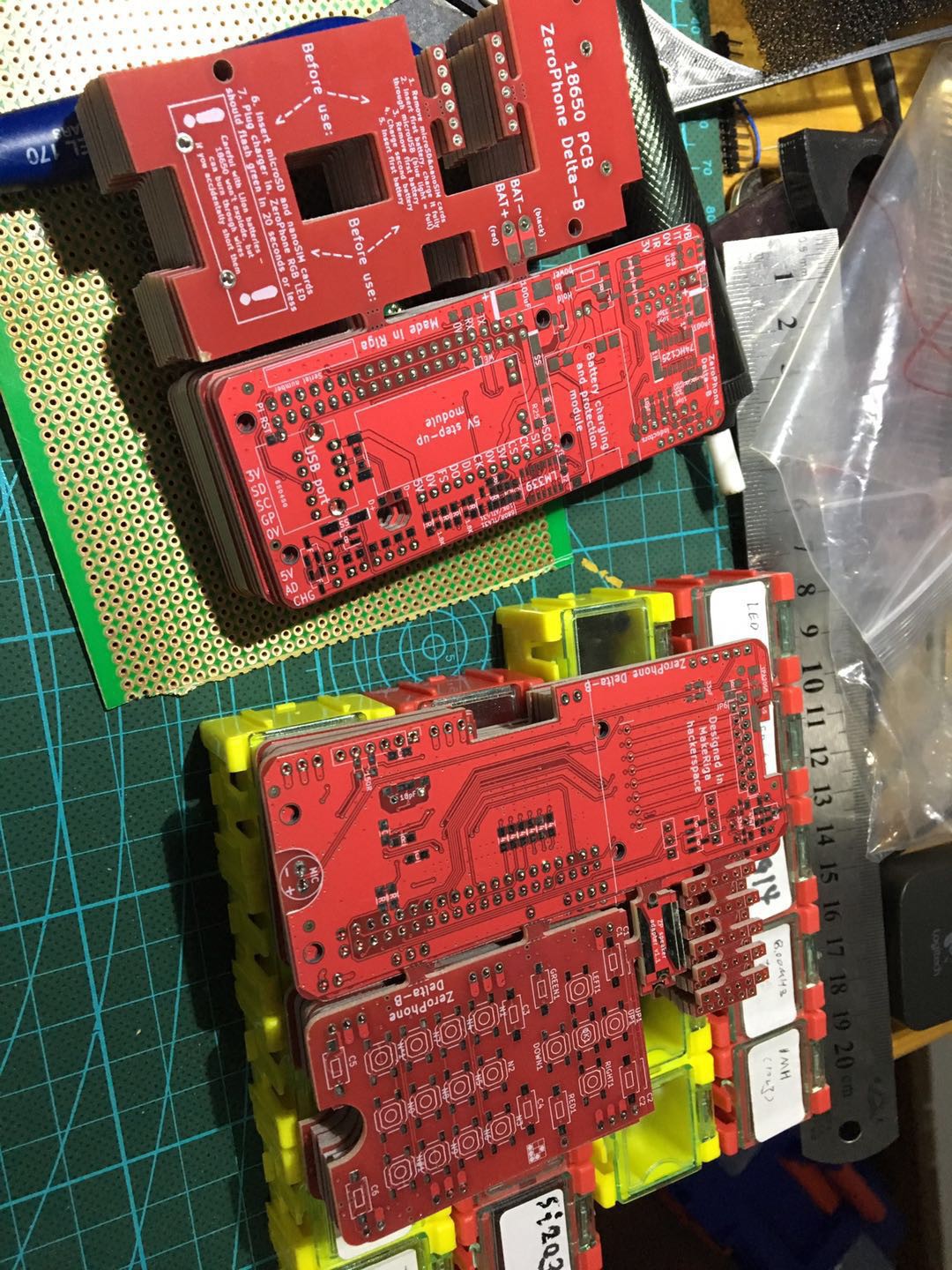
![]()
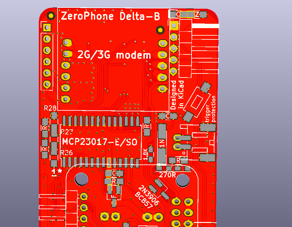
Delta-B PCBs ordered independently this year
Now, onto the reasoning behind self-assembly. For a start, I think ZeroPhone should be as accessible and get into as many hands as possible. I'm mainly interested in this because of my own background - I know it's a project that I could have assembled earlier on, fully on my own, back when I wasn't as skilled at electronics, soldering and assembly as I am now, but motivated enough to try working on projects that I believed in. I've learned there's plenty of people like that, and I think those people should be able to build their own ZeroPhone if they're so inclined. The BoM (Bill of Materials) comes down to ~$50-~$70 when you source the parts separately (and use some sourcing tricks, i.e. panelization, or buy the PCBs from someone that has them). Even if this is too costly for you (as it used to be for me), you can source parts one at a time and build the ZeroPhone board-by-board - front board first, then back board, thanks to the fact that ZeroPhone front board works with full-size Raspberry Pi boards, and is also the cheapest&easiest to build.
![]()
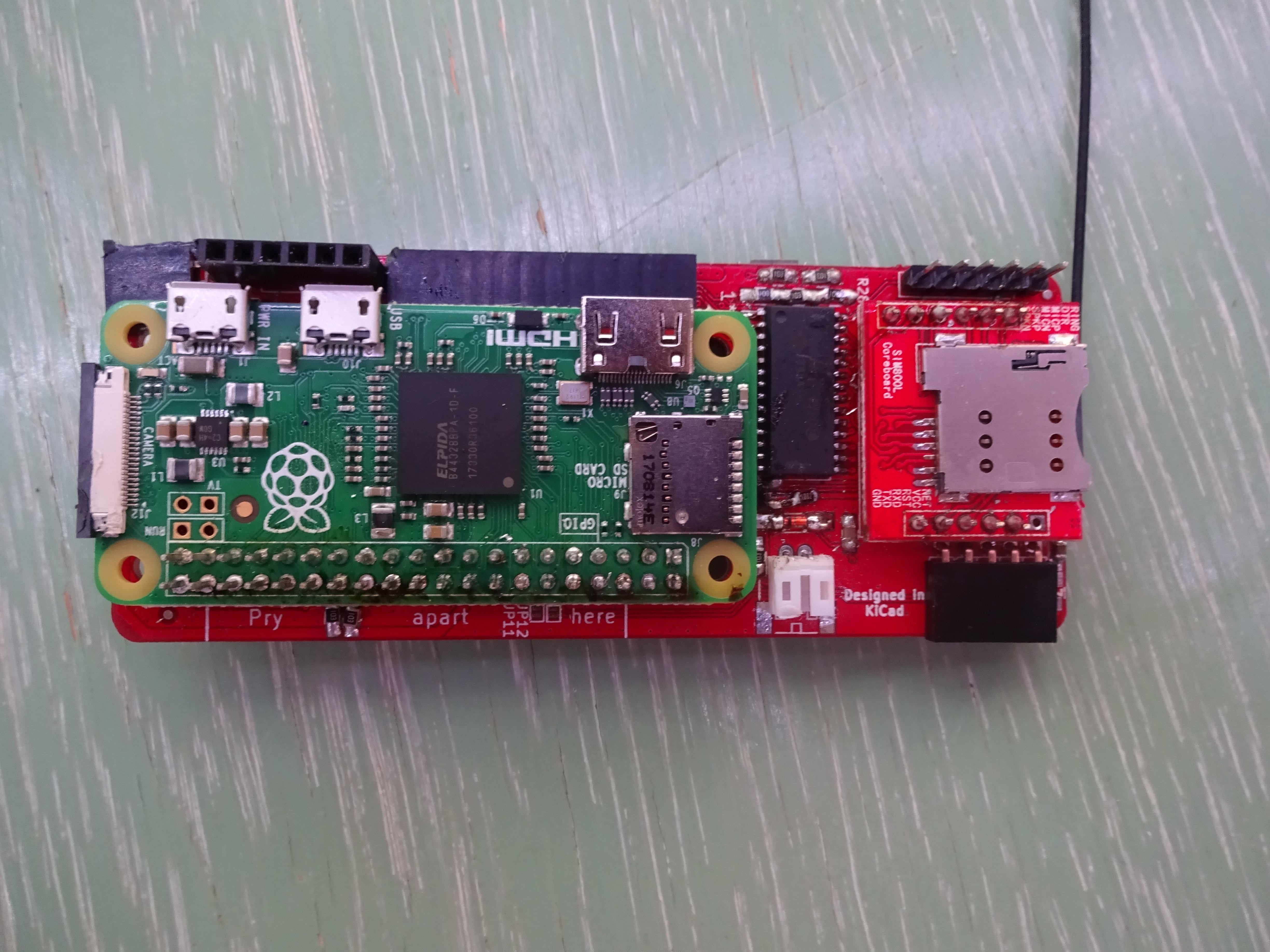
ZP front board tested on the Raspberry Pi 3
One more important thing - hardware dies out. Even larger-scale commercial devices, like Nokia N900, are starting to slowly disappear from local bulletin boards - there were only so many N900s manufactured, most of them are now either long recycled, in some trash pile or in someone's desk drawer - people that want to find replacement parts are pretty much on their own. Hardware becomes obsolete, dies or loses the software support. At some point, it doesn't make sense for the retailers to sell a device, and manufacturers drop its production long before that. Funnily enough, the more popular of an afterlife a certain phone model has, the more expensive it becomes. This effect is even more noticeable with high-complexity DIY projects, like phones or handhelds - they might be open-sourced (and often are), but if the author hasn't bothered to make a manufacturing run of them and keep the production up, you might never have an opportunity to hold one in your hands, much less own and use one. Having a phone that's as open and as straightforward as possible should make it easier for people to repair it long after we've all moved on, helping soften the effect of our fast-paced tech world on people that want stability. I've kept alive multiple devices of mine across these years, I know the motivation behind that and I know it's important.
![]()
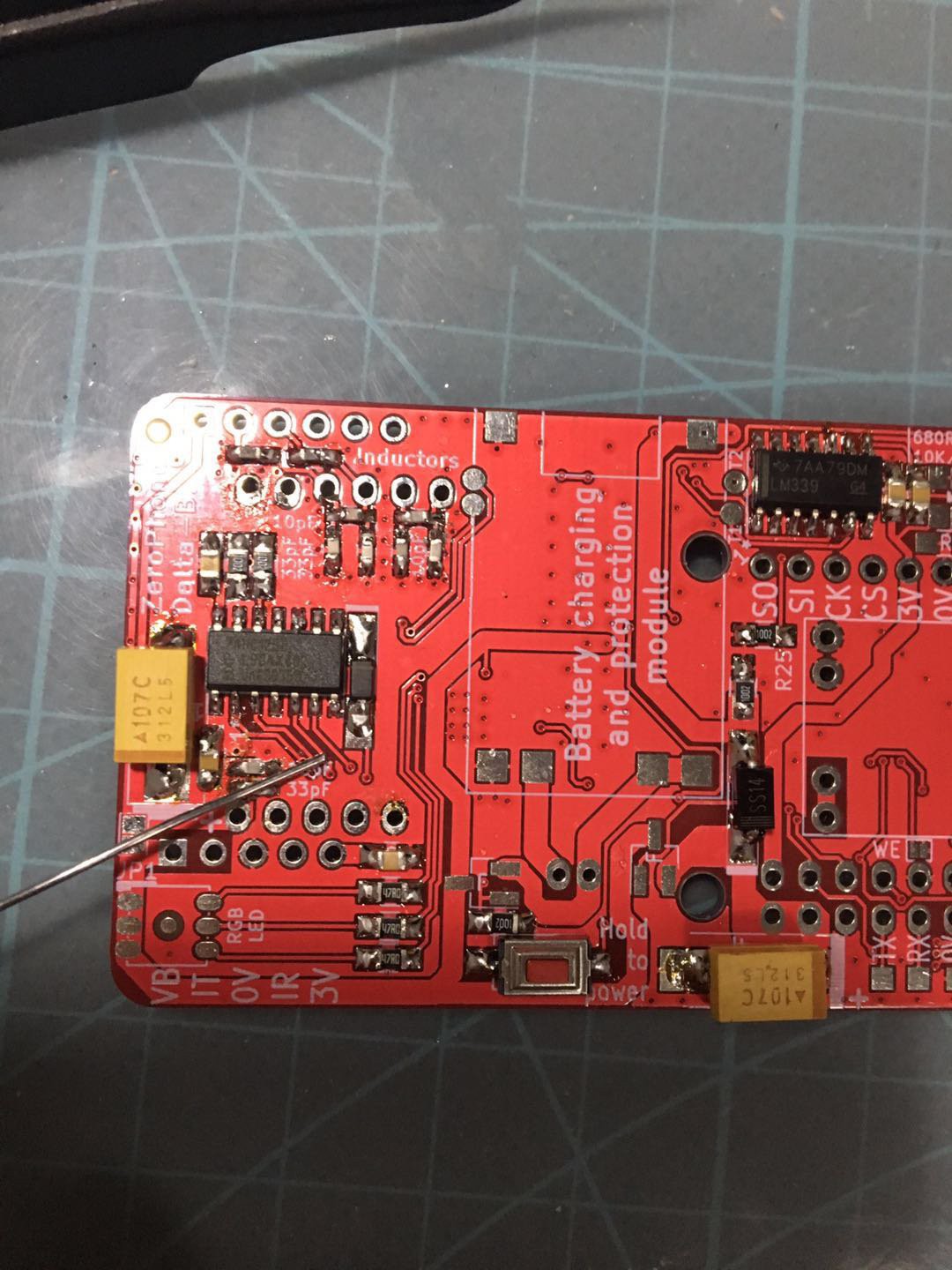
Back board in-progress independent assembly photo
Another important reason is - I believe in this project, and I want to make sure that it can continue no matter what. ZeroPhone project has the potential of living longer than my capability or interest in working on it. If something were to happen, say, I got badly ill, or dead broke before the crowdfunding and had to get a full-time job without enough time to work on ZeroPhone, or didn't start the crowdfunding campaign for whatever reason, somebody could still keep the project alive without depending on my work. It's possible with other open-hardware projects, but not to the extent that I want to have - the barrier of entry for starting work on an involved hardware-related project is usually pretty hig. My observation is that most projects never get picked up after they're abandoned, and I believe the rate is going to be higher than for software-based projects - unless the project's hardware is easy to reproduce, among other things. Sometimes I wonder if we could consider sites like Github (for software) and Hackaday.io (for hardware) as graveyards for our dead projects, in a way. I guess a major difference would be that those sites can provide a lot of inspiration for upcoming hobbyists and professionals - I could never say the same about graveyards (unless you consider "don't touch capacitors charged with 400V" to be inspirational, in which case I would agree).
![]()
Gamma boards ordered from OSHPark
Why do I put such importance on this project? Surely I don't work on any of my projects the same way, I don't give them the same level of independence as I'm trying to do with ZeroPhone. To start with, the ZeroPhone project is an example just how easy it is to assemble a phone nowadays, and how quickly one can get in the DIY smartphone scene. It also comes with a sizeable knowledge base, explaining decisions behind the project and documenting the project as it moves forward - these decisions can then be re-used by other projects, be it phone projects, Linux portables or other things that people might decide to make. Last but not least, enough people are interested in this project and like it. So, having the project in "abandoned, but you can easily assemble one" state is significantly better than leaving it in the "abandoned, was never fully finished and sold and therefore is as good as dead" state. Also, I want to set a standard of sorts for other open-source hardware projects - and help them get closer towards that standard, publishing and documenting our helper software as we go.
![]()
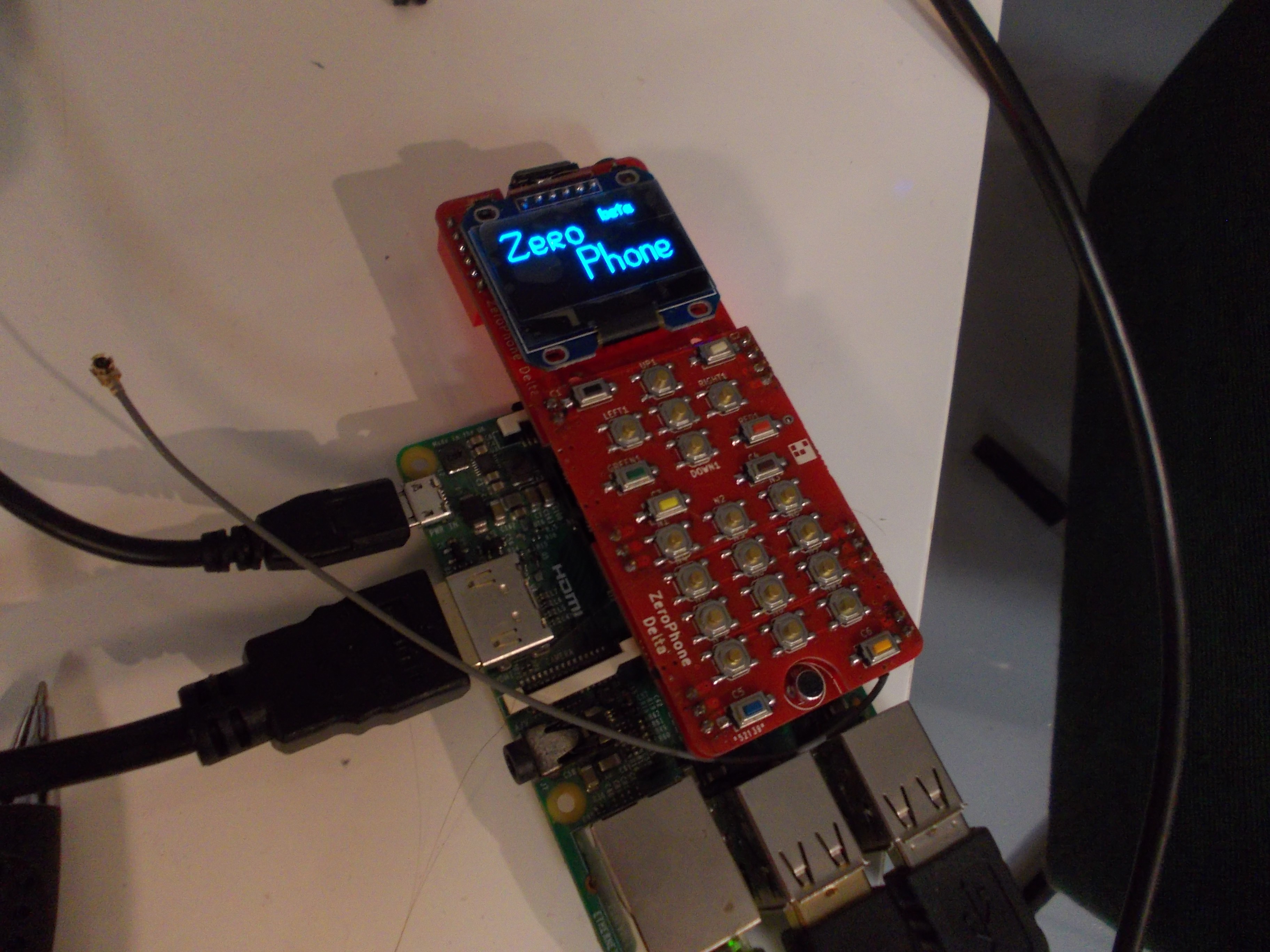
Front Delta board assembled independently this year (I sent PCBs and some small components)
Why is the self-assembly possibility one of the first priorities? I could've delivered the sourcing guidelines and assembly instructions and everything after the crowdfunding campaign, and we'd have started sooner. However, it's easier to maintain all the instructions than compile it from scratch. When a new revision of PCBs comes out, it's much quicker to copy and adjust a couple of Wiki pages - this is more evident when I look back and see just how much time it took for me to assemble all the instructions. With things I'll have to be solving when crowdfunding is ongoing, I might as well never get there! Plus, writing detailed sourcing and assembly instructions before releasing the project taught me a lot of things I didn't understand about self-assembly - specifically, places where I can optimize the project so that its assembly is even easier (for Delta revision those places were silkscreen markings, better footprints and component choice); that, of course, is going to be important for people that will receive kits.
![]()
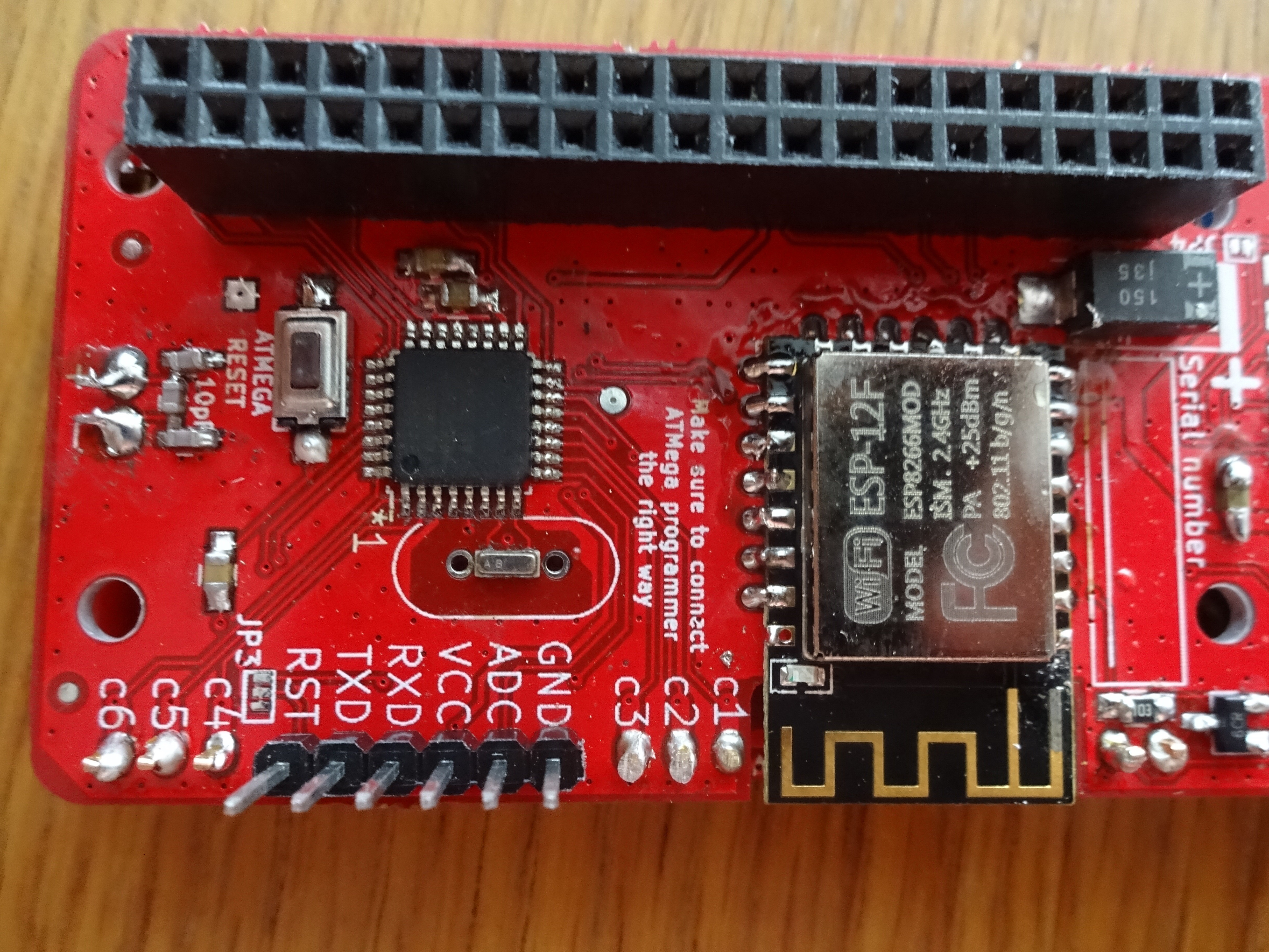
Same contributor, front board (we were debugging some ESP problems)
As I've discovered through these two years, there are places where self-assembly isn't compatible with larger-scale manufacturing. When I'll be manufacturing kits, I'll be ready to step away from self-assembly-optimised solutions in favor of those that will make the manufacturing process more reliable and assure delivery of kits to those that order it. However, the self-assembly-capable version will remain there, so that people will be capable of assembling ZeroPhone on their own, no matter what happens during production.
Would love to hear your thoughts on that - this is not something that I haven't got a lot of feedback about in surveys and letters, but I'm sure there's something I'm wrong about, or something I'm missing.
-
Delta-B released!
10/26/2018 at 23:59 • 0 commentsHi! Here's a long overdue worklog about a new revision that was released two months ago =D It's called Delta-B, the only changes from Delta are bugfixes; this time that's actually true - not like Gamma=>Delta which was planned to be like a bugfix-only revision, but had to get lots of additions.
![]() ---------- more ----------
---------- more ----------Why? When I received an offer for PCB sponsorship from JLCPCB (funding the free kit batch), I didn't even have an assembled&working Delta ZP. My previous ZP experience taught me that it's important to fully test PCB additions before releasing the next version, and I decided to seize the moment and release a version of PCBs I could consider "stable". So, I went on a series of Twitch streams (which you might remember), assembling a Delta ZeroPhone and testing it, then designing the new revision. What were the problems?
- The charger-to-USB switchover circuit didn't work properly. What's that? It's a circuit I added to allow powering the USB power from 5V on the charger input when the charger is connected. How do you fix it if you have the Delta (not Delta-B) PCBs? Here are the instructions.
- The I2C HAT EEPROM didn't work properly. Why's that there? To allow us to distinguish between different PCB revisions in software. How do you fix it if you have the Delta (not Delta-B) PCBs? Here are the instructions. Also, I've designed and will soon receive PCBs to make the fix easier, so you don't have to deadbug a fix and can just ask me for a small board - again, in case you ordered the Delta PCBs, the Delta-B has all of that built in.
- There are some silkscreen and footprint fixes - some values were incorrect, some polarities were unobvious, some footprints (1) (2) were wrong or confusing... Basically, stuff that could trip people up during self-assembly - and since Delta was designed for ease of self-assembly, it only made sense to look out for such bugs
- Certain charger&protection boards (with "flaps" at the BAT/OUT end) would mechanically interfere with two components. Small, but annoying problem - hopefully, fixed.
- I didn't know that there's a certain range of voltages that the comparator I'm using can compare - basically, it can't compare voltages in the 0 to VCC range, only in the 0 to VCC-2V (0 to 1.3V) range, things outside that are the hardware version of undefined, and of course I picked reference&compare voltages in that range. Still haven't figured that one out fully, for now, I'm not paying much attention to the comparator (and will consider removing it in the future revision).
That's mostly it. As usual:
- GitHub PCB release (also has gerbers and schematics exported neatly into separate .ZIPs, ought to automate that)
- OSHPark links: front board, back board, keypad board, 18650 board, speaker adapter (not hosted by me, this time - someone else got there first! =D )
- New shiny thing! Assembly helper that's based InteractiveHtmlBom, in other words, it's wonderful and check this out: front board and back board. Irreplaceable if you want to do self-assembly.
That's it for now. Hope to publish something else interesting here soon - otherwise, this blog is kinda abandoned =)
-
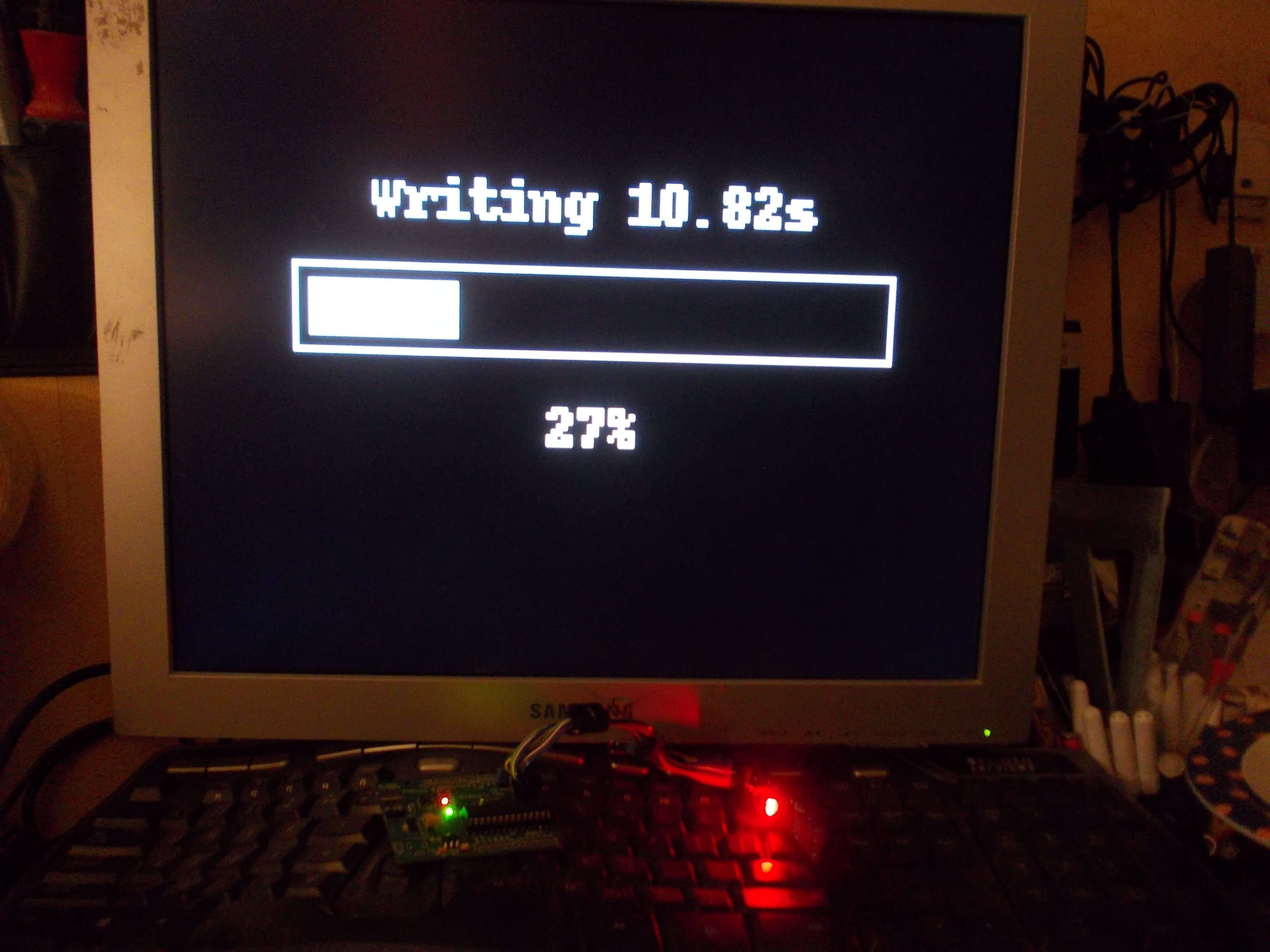
New app - avrdude
07/01/2018 at 22:20 • 0 comments![]()
This month, I've been working on an avrdude app - an app that uses avrdude to program AVR microcontrollers. It's now finished, with 500 LOC in the app itself and 800 more in the associated libraries. You might be surprised - why this and not something else, like a messenger app? Here are the reasons:
- At the time, I had a small gig that involved programming 50 ATMega-based boards. So, after working with avrdude for quite a while, I was quite sick of it and wanted to automate it away - and also wanted to make sure there's a straightforward way to burn popular bootloaders to ATMega-based boards, which is a big part of this app. Now, I don't need to be summoned anywhere to program a new batch of boards - I can just give that person a ZPUI-enabled device with a user-friendly interface.
- ZPUI needed a helper class to run long-term processes and parse their output - which is something that avrdude app would need, so after I wrote it, it only made sense to write an app around it. Such a class will be necessary for anybody who would want to write a wrapper to run any command-line tool and see what it outputs in real-time - be it ffmpeg or mjpg-streamer (which I plan to add for single-click video streaming), an interactive CLI script that needs your password, another microcontroller flasher or just a long-winded script that you want to monitor, there's now a way to wrap it in a developer-friendly object you can use to get output, send output and terminate the process at a whim (surprisingly, something that I still haven't found a proper Python library for).
- I wanted to understand whether there's something that ZPUI lacks - it's something you can only see while you're programming a large app like this, and given that I'm the only person working on ZPUI and controlling its direction, it's crucial for me to check every once in a while if there's something that could be added to ZPUI. As a result of this work, I've added a lot of new functions, and more different ways to use the existing ones.
- Also, I wanted to test out the recent ZPUI additions - like context switching, canvas system and class-based apps, and write a large app that uses all these things in a way that others can then refer to. While I was writing this app, I uncovered plenty of bugs and inconsistencies, which were promptly fixed.
- Last but not least, writing large apps gives me the experience I can use to advise others on writing large apps - for now, nobody but me has this kind of experience, which is necessary to help people writing large apps that actually work.
The end result is an Atmel MCU programming app that can backup and restore firmware from/to the MCU, flash arbitrary .hex files and bootloaders. For now, I've only tested it with usbasp programmers, but linux SPI device and other programmer support will be coming soon. I've used it a lot already, and it's even more useful given that I'm now working on several AVR-powered ZeroPhone mod boards (so, a simple way for users to update the mod board firmware is needed). It also has pinout information and the most crucial settings available, as well as some user-friendliness related features. In addition to that, there's a lot of bugfixes, improvements, new ideas for improving ZPUI and insights into problems that ZPUI has.
One large problem that I now understand ZPUI has - lack of some kind of markup system for UI design. Essentially, when you're trying to draw your own UI, you need to calculate position of each element on the screen, requiring plenty of math (and extra variables) if you don't want parts of your UI to overlap/disappear. When it comes to text, the situation is even worse - as of now, it's pretty much impossible to properly word-wrap arbitrary text on a screen, for example. What do we do about it? I have no idea yet, and that's something I'll need to address sooner or later, unless I want ZeroPhone to be infamous for ugly apps... or not scaling further than the small display we're currently confined to.
![]()
There are also some problems regarding UI elements not being universal enough - for example, there's no way to have a Nokia-style settings menu (a menu with combined checkboxes, listboxes and sliders), combining lots of different settings in an easy-to-use view. Input UI elements still aren't any good, either, I expect to work on them once I get to the SMS-related apps, which will happen soon - I'm working on the modem integration with ofono now, continuing work that monsieur_h started. In general, I'm thinking about the UI a lot now - can't wait to make a proper main menu, with icons in a grid and everything!
-
Delta boards released!
05/24/2018 at 00:40 • 2 commentsThe new revision, ZeroPhone Delta, is out. I've been using a Gamma ZeroPhone for quite some time now, and it needs some bugfixes. Specifically, I:
- Fixed a mechanical weak spot where a row on the keypad would break due to lack of structural support
- Fixed tantalum capacitor footprints - now they're more solderable
- Fxed the problem where traces on the 18650 board would get exposed to the back board (and short things together) due to soldermask scraping off the back board when scratched by the back board through-hole pins
- Flipped the 3G modem upside down, making the routing significantly easier
- Reorganized the SPI (side) expansion header footprint, changing it to use 12-pin headers (easier to source)
- Reorganized the I2C expansion header to be compatible with the Raspberry Pi I2C pinout, allowing to connect existing I2C RPi expansion boards to ZeroPhone
- Reorganized the IR (top) expansion header - now it's safe to plug expansion boards in reverse
- Audio buffer, vibromotor and keypad backlight circuits are now powered from VSYS
- Flipped the DC-DC power FET so it's no longer necessary to solder it flipped
- Flipped the charger board - now it's easier to solder it, as well as swap and test
- Made the Pi Zero pads on the back board oval - making them stronger (for rework purposes)
- Changed the 4-pin GSM audio header into a 6-pin one - for easier sourcing
- Improved the microphone footprint on the front board
- Made fiducials smaller - mostly I needed more space for routing
- Improved the switchable display header - the jumper pads are now smaller, and through-hole part of it is covered by soldermask on the front of the board (to avoid displays shorting to it)
- Made the surface-mount crystal resonator pads on the front board larger, in attempt to make the resonator hand-solderable
- Added traces to the MCP23017 footprint in an attempt to make it more reworkable
Here's what I added:
- Inductors in series with GSM microphone traces - for noise filtering
- Assembly instructions/guidelines on front, back and keypad boards
- Usage instructions on the 18650 board
- Expansion header pinouts on the back board
- A comparator - detecting charger&USB undervoltage and charger board overheating
- A circuit that'd allow sensing whether the "power switch override" button is pressed while still eping the phone switched on
- An UART buffer - not connecting the GSM UART to the Pi UART until a GPIO is asserted
- UART testpoints near the charger board outline - to allow for a charging+UART board to be made
- Serial number fields on front, back and keypad boards
- An audio amplifier for the GSM speaker (unfortunately, it's a TI part - I'll be looking for a substitute)
- An I2C EEPROM to GPIO0 and GPIO1 to the back board - to make the back board work as a Pi HAT in software
- Better power filtering for the GSM modem power
- A "connect 5V DC-DC to the charger input when the DC-DC is powered off" circuit
- 3.5mm jack audio filtering to remove GSM noise
- ATMega UART header reverse polarity protection
- A fuse to the 18650 board between two batteries, to avoid problems when people insert batteries in reverse, or batteries with different levels of charge
- Finally designed the first solution to attach the GSM speaker
I also removed a lot of things that didn't prove themselves useful:
- The RTC footprint - proved to be unnecessary and incomplete, and was taking a lot of PCB real estate
- The GND-BATT- jumper - wasn't useful
- The capacitor footprint in parallel with BATT+ and BATT- - wasn't useful
- The MPU9050-compatible footprint - wasn't useful enough compared to the PCB real estate
- The second USB socket (facing the board center) - wasn't useful
- The RST and TV-OUT pad connections - weren't useful (though having a way to bring them back later would be cool, maybe add a pad for a surface-mount pin header?)
OSHPark links: 18650 board, back board, front board, keypad board and speaker adapter
Some of these points (like silkscreen additions) could be explained further, but I'll show them off once I receive the boards and make the assembly guides. This is pretty much the gist of the Delta release. There's a lot of safety, usability and reliability fixes - not so much in terms of features, but, as you know, adding things means adding bugs, and I couldn't really afford to have a lot of those in this revision. This revision is the one I'll be promoting once I get it and assemble a phone or two - I finally feel like i can put trust in a revision that I've made, and I can safely calculate the crowdfunding campaign expenses based on its BOM.
Now what? I need to do a bunch of work on software. A new SD card image is long overdue (and I really need to look into automatically building these), and I finally can work on integrating the part that deserves my attention the most - the GSM modem. I will also make a video assembling a Gamma ZeroPhone from scratch - I don't think making full-blown assembly instructions is a good idea (since even the errata takes too much time), but I'll be doing that for the Delta model.
Heads up - I've also designed a ton of expansion boards (many of them at the last couple of days before ordering). There's even a cool SPI level shifter - it shifts 3.3V to 1.8V if you insert it one way, or 3.3V to 5V if you flip it over! Hope you like them - compiling a list of them soon ;-P
-
Some ZeroPhone problems I'll be fixing
02/15/2018 at 09:26 • 7 commentsEven though I've put a lot of work optimising ZeroPhone for everyday usage, self-assembly and manufacturing, there still are things we can do better in the next revision. Let's go through them, so that you can see the final changes I need to make to the boards, and things I need to figure out before the crowdfunding!
![]()
This list is a result of me carrying a ZeroPhone with me through this year - and, therefore, fixing these problems will make sure your ZeroPhone lives as long as possible and is not merely some kind of gimmick that dies after a couple of months. Most of these problems are either fixable or have workarounds - if they didn't, I wouldn't have had been able to assemble the Gamma PCBs. However, they will be problematic for new people, so I have to make sure to eliminate as much of those problems as possible for the next version - to properly achieve the ZeroPhone "self-assembly" goal, making the assembly "as easy as possible" and not just "possible".
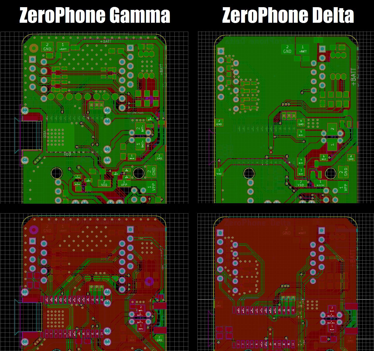
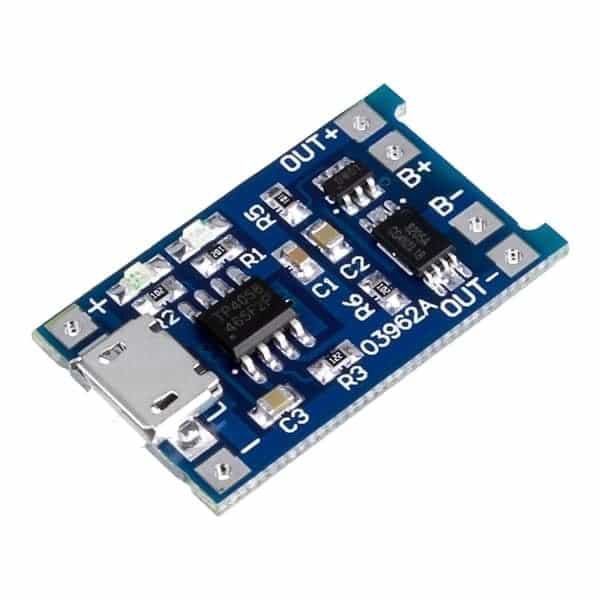
Charging and protection boards
![]()
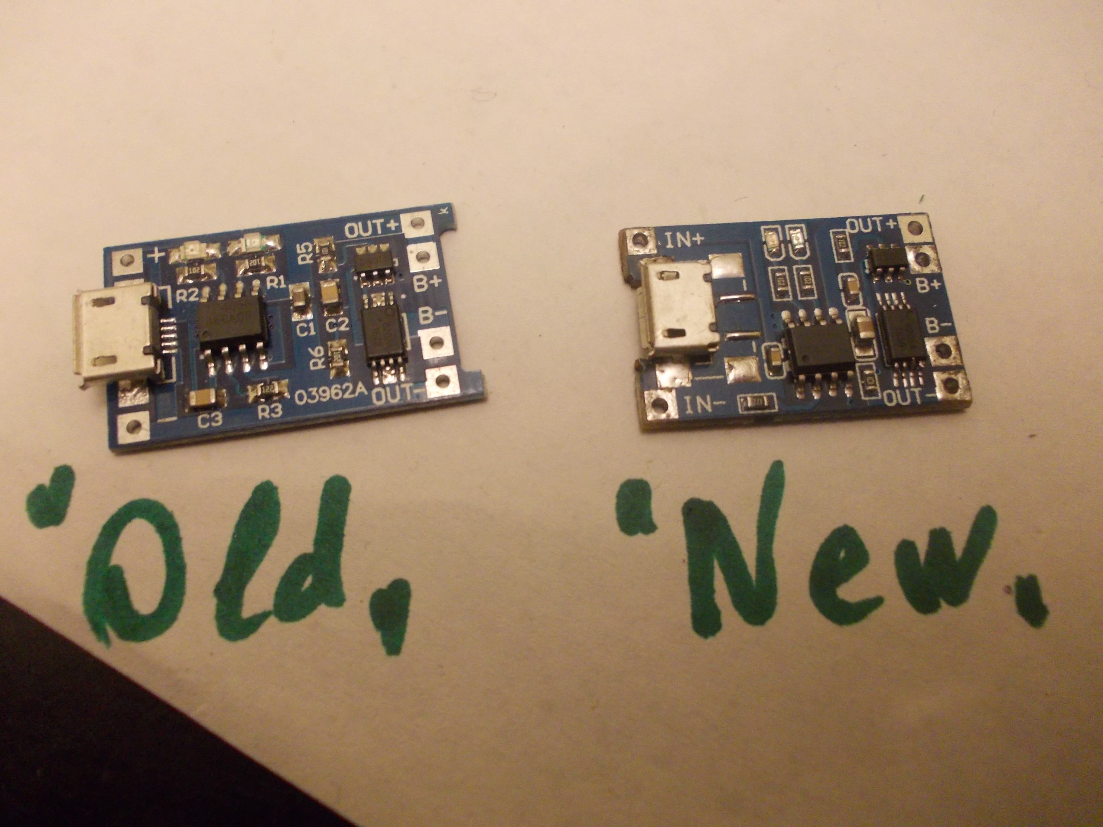
We use popular modules from China for the ZeroPhone battery charging and protection. I had problems with the way those modules had to be soldered on the back board - it wasn't straightforward, and it wasn't easy to get done. So, I've flipped the footprint - now it's compatible with more module types, and it's much easier to solder the modules on - the board layout also became much more straightforward, since power traces used to be crossed and now they aren't! The component side of the modules is now exposed to the outside of the phone, though - I'll have to make sure this doesn't cause problems, such as short-circuits (possibly, release a 3D-printable cover).In addition, there were stability problems with a new version of these modules. Beta boards were using an earlier version:
![]()
For Gamma boards, however, I used slightly different modules, a newer version - I ordered them by mistake, so I quickly changed the footprint to fit the new modules in order to avoid ordering the older ones.That turned out to be a bad idea - the newer modules seem to not function as well as the previous, some of them randomly fail (luckily, they fail safe). It happened to some of my ZeroPhones, and it also happened to some of the ZeroPhones that I sent out (which resulted in the person having to send it back, for me to repair, and that's something I'd really like to avoid). That's not acceptable - if the module is broken, ZeroPhone cannot operate from the battery at all - or it switches off randomly, which is even more annoying. Fortunately, the new, flipped footprint allows for all kinds of modules, so it should be easier to find a suitable board now!
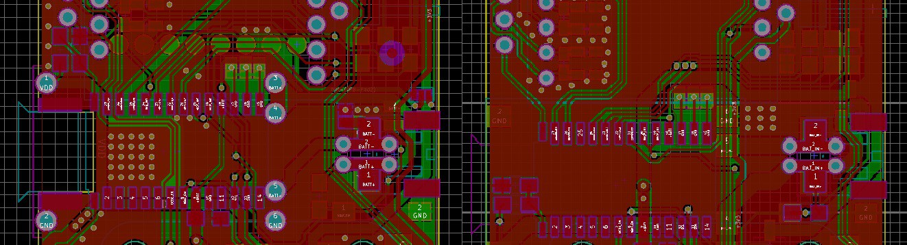
![]() During the manufacturing, we'll need to find a way to either find a reliable source for these modules, or to manufacture our own (I've already reverse-engineered the schematics and the PCB, thankfully, and I'm asking for manufacturing quotes) - as a backup plan in case the commercial modules are no longer suitable for us. I've also tried understanding the problem by comparing "old" and "new" modules - I've checked the schematic and it's the same (the boards are slightly different, but the changes are minimal), so my guess is that the "new" modules are using cheaper components, which causes the failures. But, just in case, I'm going to see if there's a way for us to source these boards reliably.
During the manufacturing, we'll need to find a way to either find a reliable source for these modules, or to manufacture our own (I've already reverse-engineered the schematics and the PCB, thankfully, and I'm asking for manufacturing quotes) - as a backup plan in case the commercial modules are no longer suitable for us. I've also tried understanding the problem by comparing "old" and "new" modules - I've checked the schematic and it's the same (the boards are slightly different, but the changes are minimal), so my guess is that the "new" modules are using cheaper components, which causes the failures. But, just in case, I'm going to see if there's a way for us to source these boards reliably.Reworkability
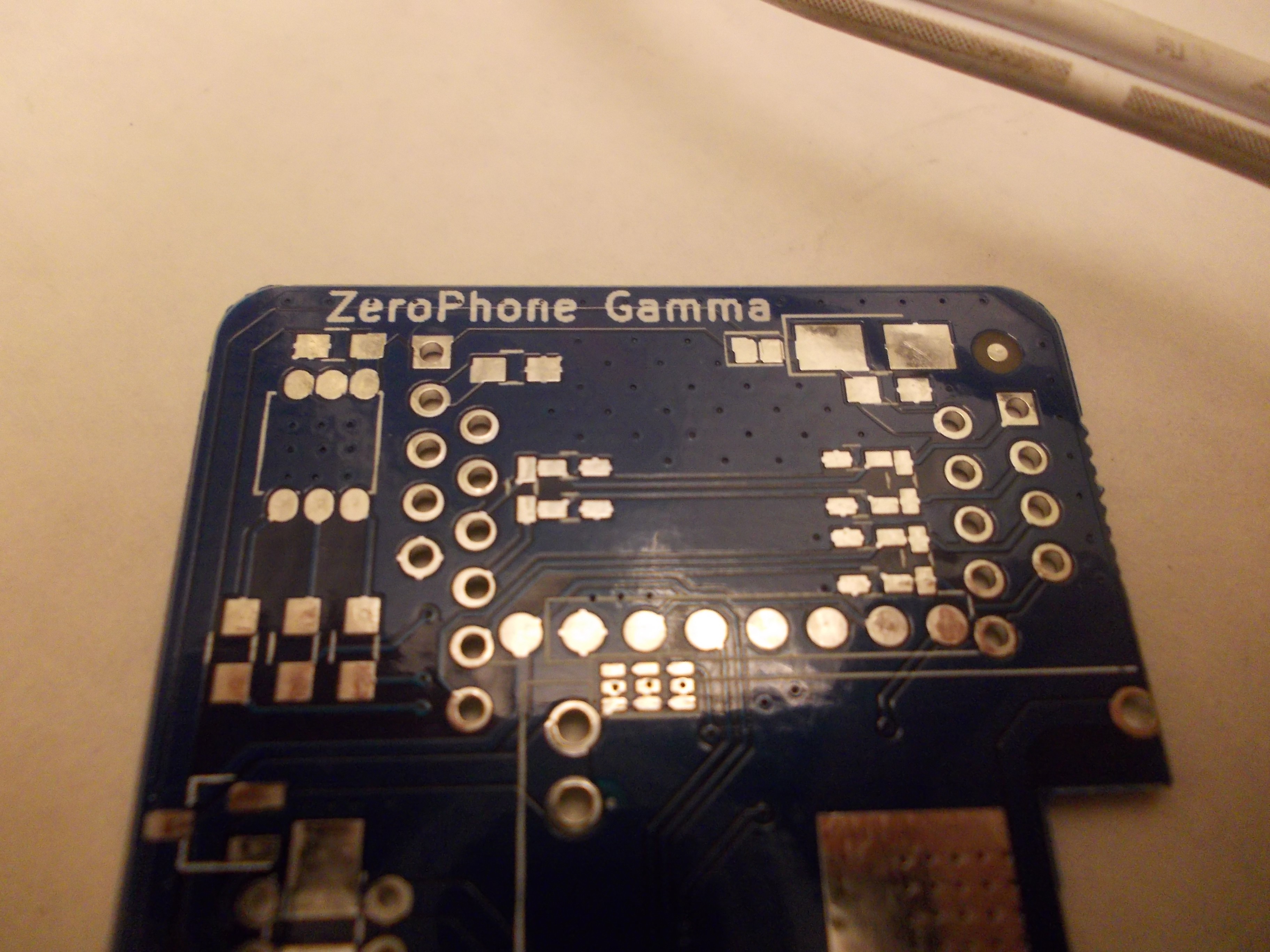
![]()
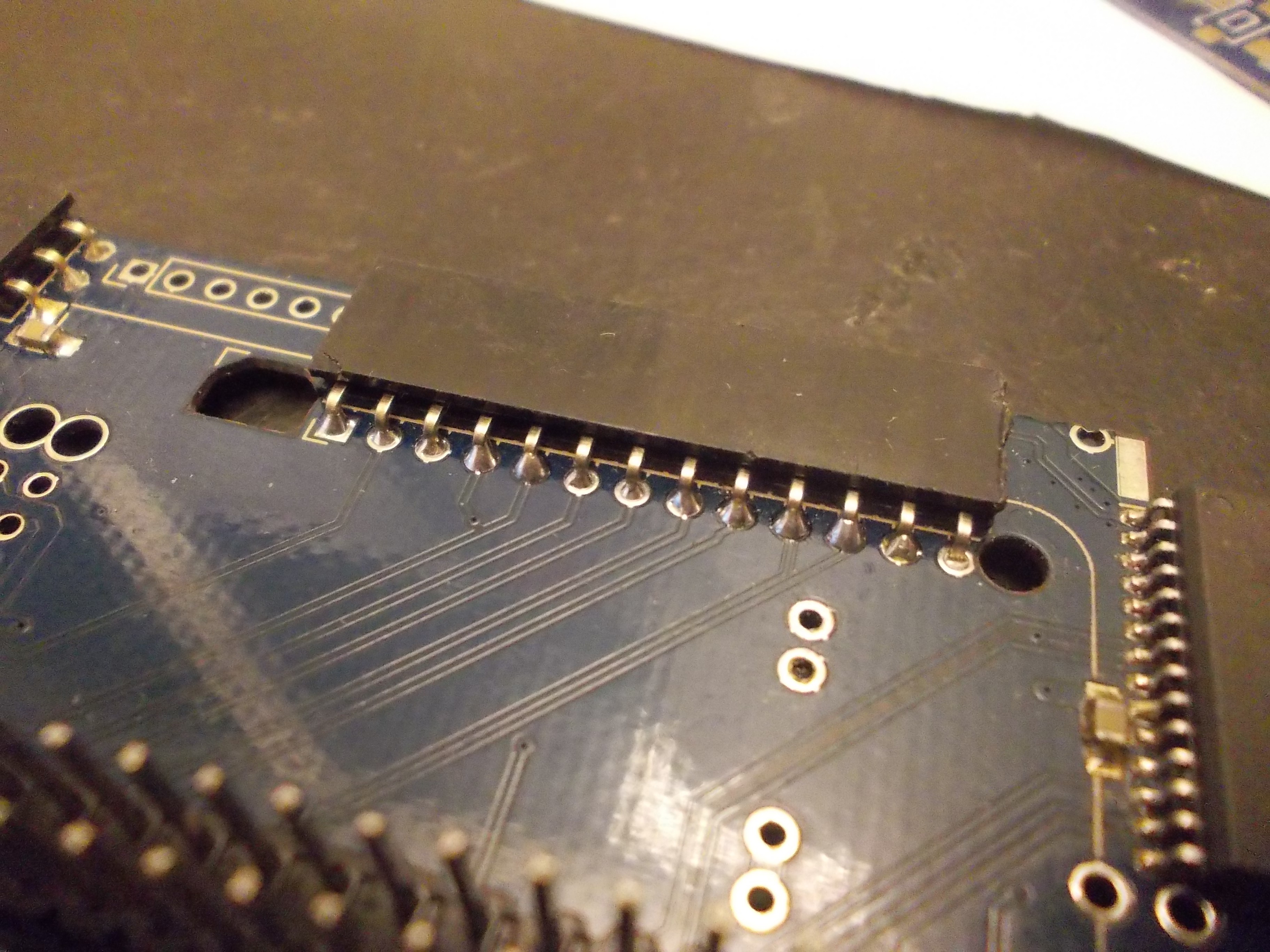
It turned out that current ZeroPhone PCBs might have some problems while doing repairs - traces breaking, pads being lifted etc. Generally, it will only happen to low-quality PCBs - but it's hard to make sure the PCBs you're ordering are of sufficiently high quality (and if you're ordering from a place like DirtyPCBs, it's likely your PCBs won't be good enough to survive overheating). This is bad, since it makes ZeroPhone less repairable - in the end, I have two back boards and one front board that are unusable because too many pads got lifted, and I also have some more that need wire fixes because of pads that fell off. Granted, many problems appeared because of me overheating some of the boards during reflow - but it's a mistake that could be easy for people to make, and if it's something we can safeguard from without any big problems, why not adjust the boards for that? I will have to check whether my modifications will result in a design that's still easily manufacturable, though.![]()
In addition, many pins are tricky to solder. The exposed copper ring around the pins is small, so it's hard to heat the copper up, which results in having to wait longer to make each solder joint - while the flux is burning out and the part is needlessly heated, which, again, can contribute to the pad eventually detaching. I will likely enlarge most of the pads on the connectors, making sure that soldering will be as quick as possible.Converting back board to a 4-layer PCB
The back board is the most complicated ZeroPhone board - it has power management, GSM modem, the GPIO expander and expansion ports on it. So, the layout is cramped, and making big changes is tricky. I feel like the layout is pushing the limits of 2-layer PCBs (and many people have told me the same over the last year), and at some point it might result in stability issues. While my charger&protection board and GSM breakout changes have improved the situation dramatically, adding two layers would help a lot - the internal layers could be used as ground/power planes, so it'd be easier to layout numerous signals present on the back board, and it could decrease the inevitable noise that all the signals and power paths will produce. Also, it would allow us to better layout the board, so that adding features to it would be much easier in the future.
The downsides? 4-layer boards are somewhat more expensive and harder to order for hobbyists. You can't panelize them as easily, which means that you wouldn't be able to get by with ordering two 2-layer 10x10cm panels, and would have to order two 10x10 panels + a 4x10cm 4-layer board, which would result in a $28 increase in case of ordering on DirtyPCBs, or double the price in case of OSHPark.
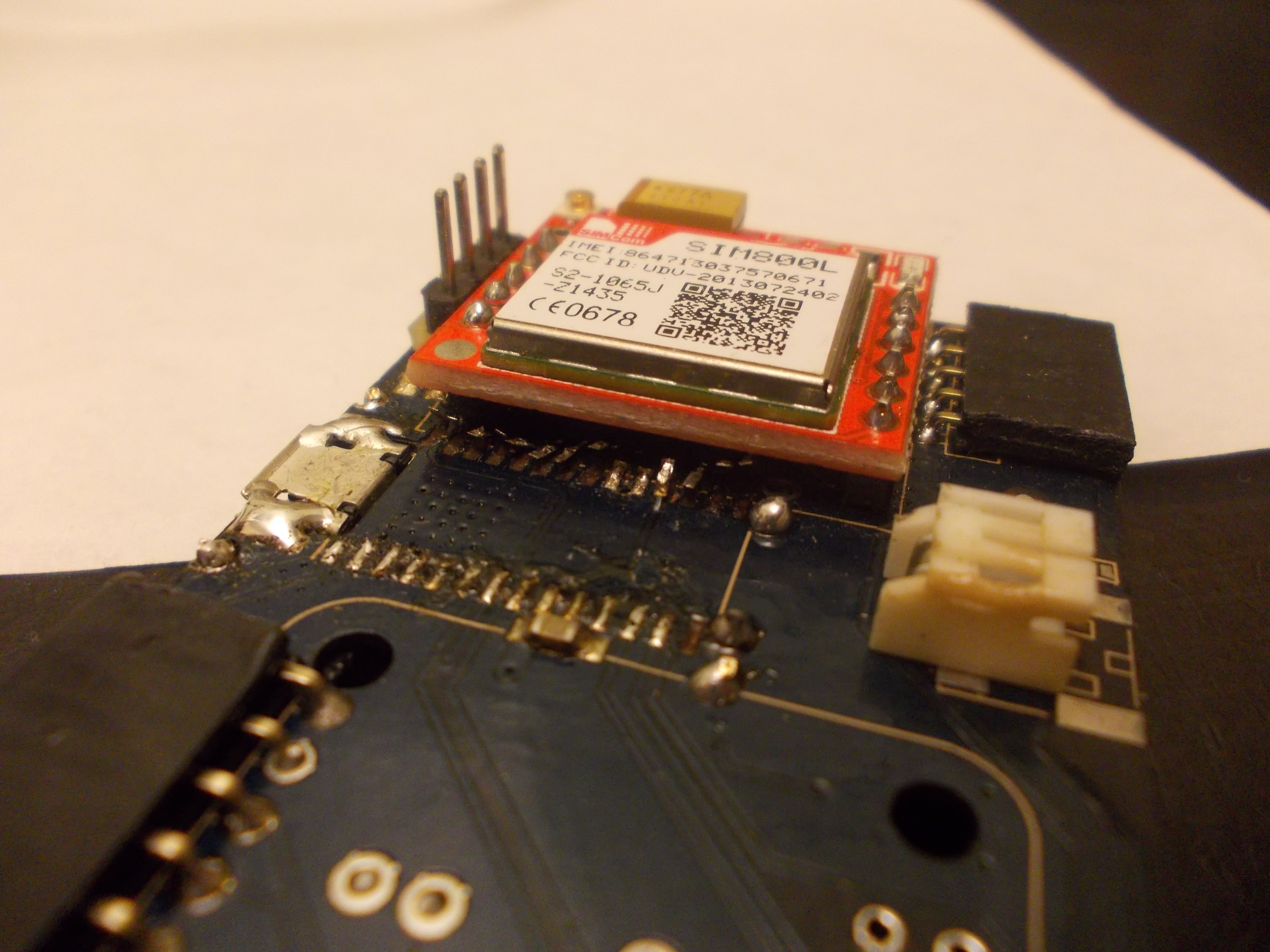
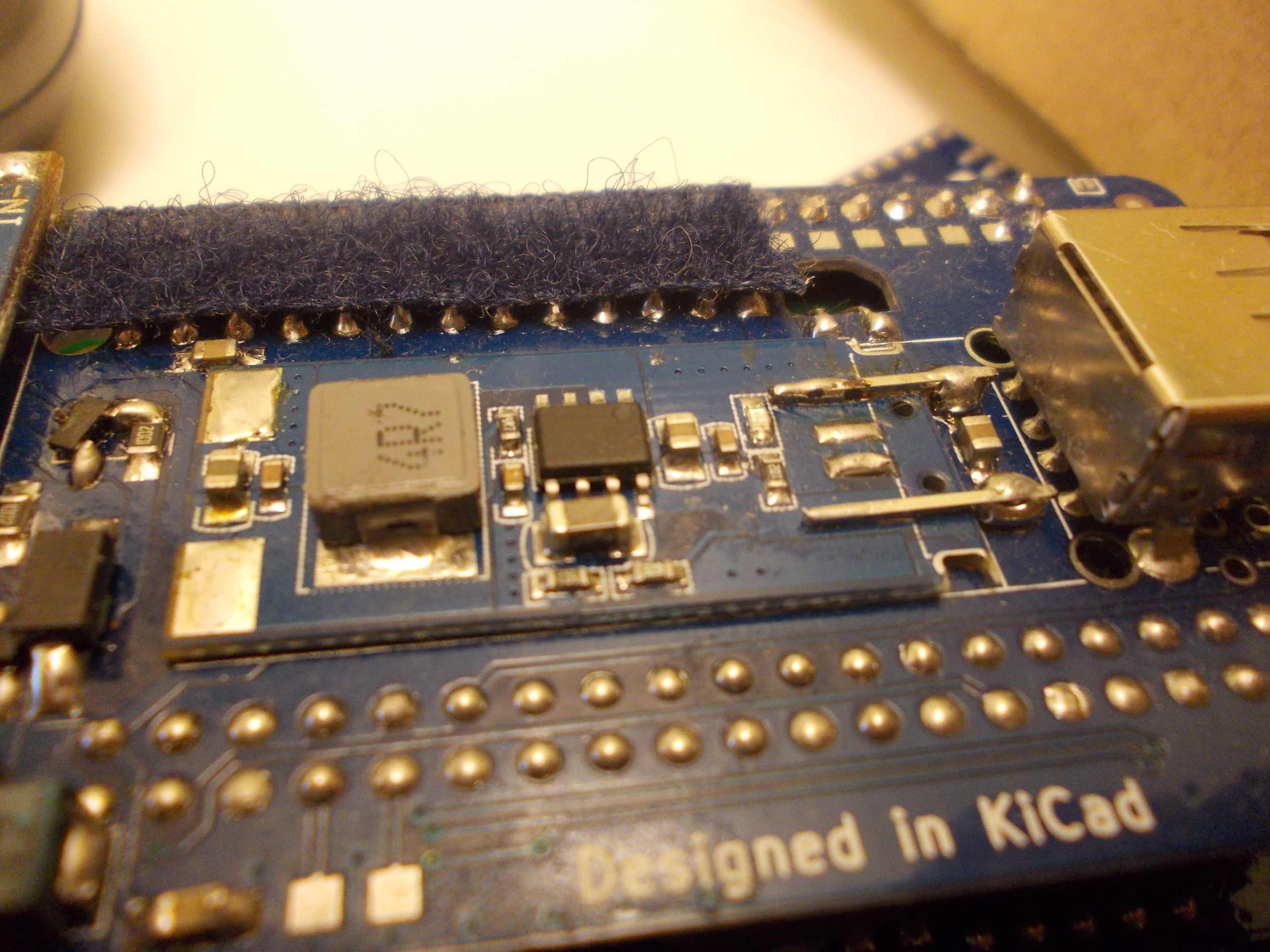
GSM modem
![]()
The GSM modem connections on the back PCB were crossed - audio went from right to left, and power&control signals went from left to right. This is not good - it introduces noise in the audio lines (which was one of the issues prominent on Gamma ZPs I assembled), as well as makes the layout less straightforward. So I've flipped the modem breakout vertically. This means that the SIM card holder is now up, and the modem itself + the antenna connectors are now down (between the modem breakout PCB and the back PCB). The new placement improves the layout, but there are two new problems: 1) the big capacitor on the breakout PCB is too tall, so it likely will bump into the PCB 2) the antenna will be harder to attach, since now it will have to be inserted between the back PCB and the module PCB. I hope I find some kind of solution to these two problems, since, I have to say, the layout is considerably better now and I don't feel like going back =)
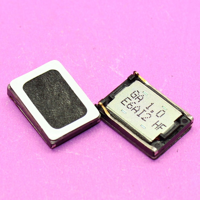
Speakers![]()
From the start of ZeroPhone, I never really factored speakers in, I hoped to use something like ubiquitous Nokia speakers when the time comes. It turns out I can do it, but there's a trick - most of these speakers are not meant to be soldered, but instead to be tightly sandwiched between the phone's case and the phone's motherboard, and in case of ZeroPhone they can only be soldered. I could theoretically use some kind of round speakers with wires already attached, but that'd limit our options, and it might not have as good of a sound quality. Also, the space above the display is already pretty limited - a round speaker just won't fit, since they tend to be pretty large. So, I'm looking for a solution to that - the Nokia speakers are definitely solderable, so I'll likely make a "carrier board" to solder the speaker on; that board would, in turn, be soldered onto a ZeroPhone front board. This solves the problem, but I have to see if this is *the* solution.13-pin header
![]()
On back boards, I've used a 13-pin female header for an extension port, and I forgot to check if these are commonly available - turns out, they aren't. Fortunately, I can easily make it 12 without losing anything of significance (though TV-OUT will have to be available on its own header, likely unpopulated by default). Also, replacing a 13-pin header with a 12-pin one will actually make the board more manufacturable, since the plated holes are located too close to the board cutouts. So, 12-pin headers it is!
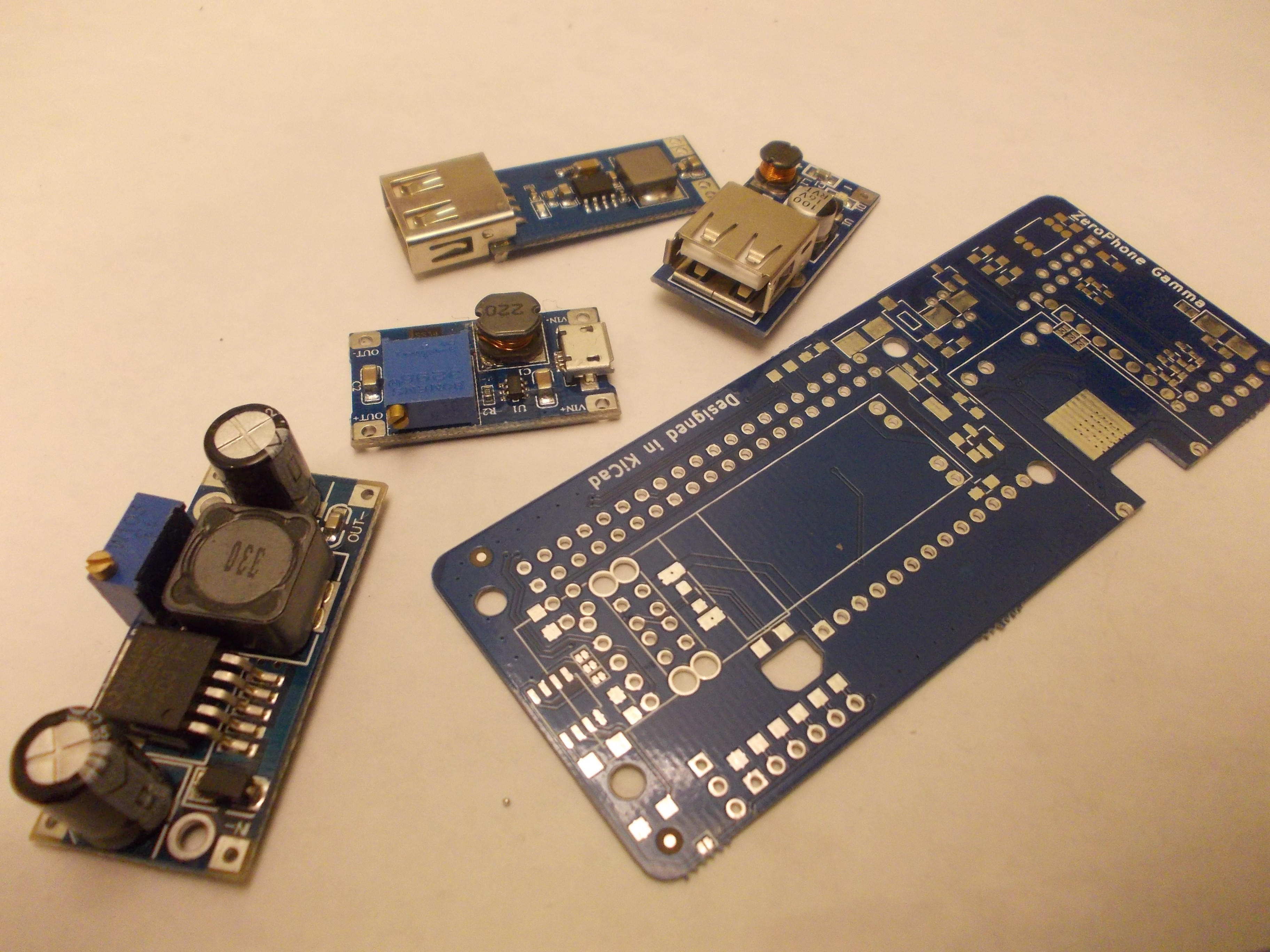
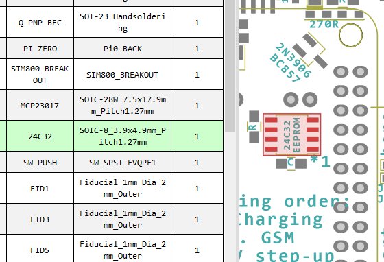
5V step-up (DC-DC) module
![]()
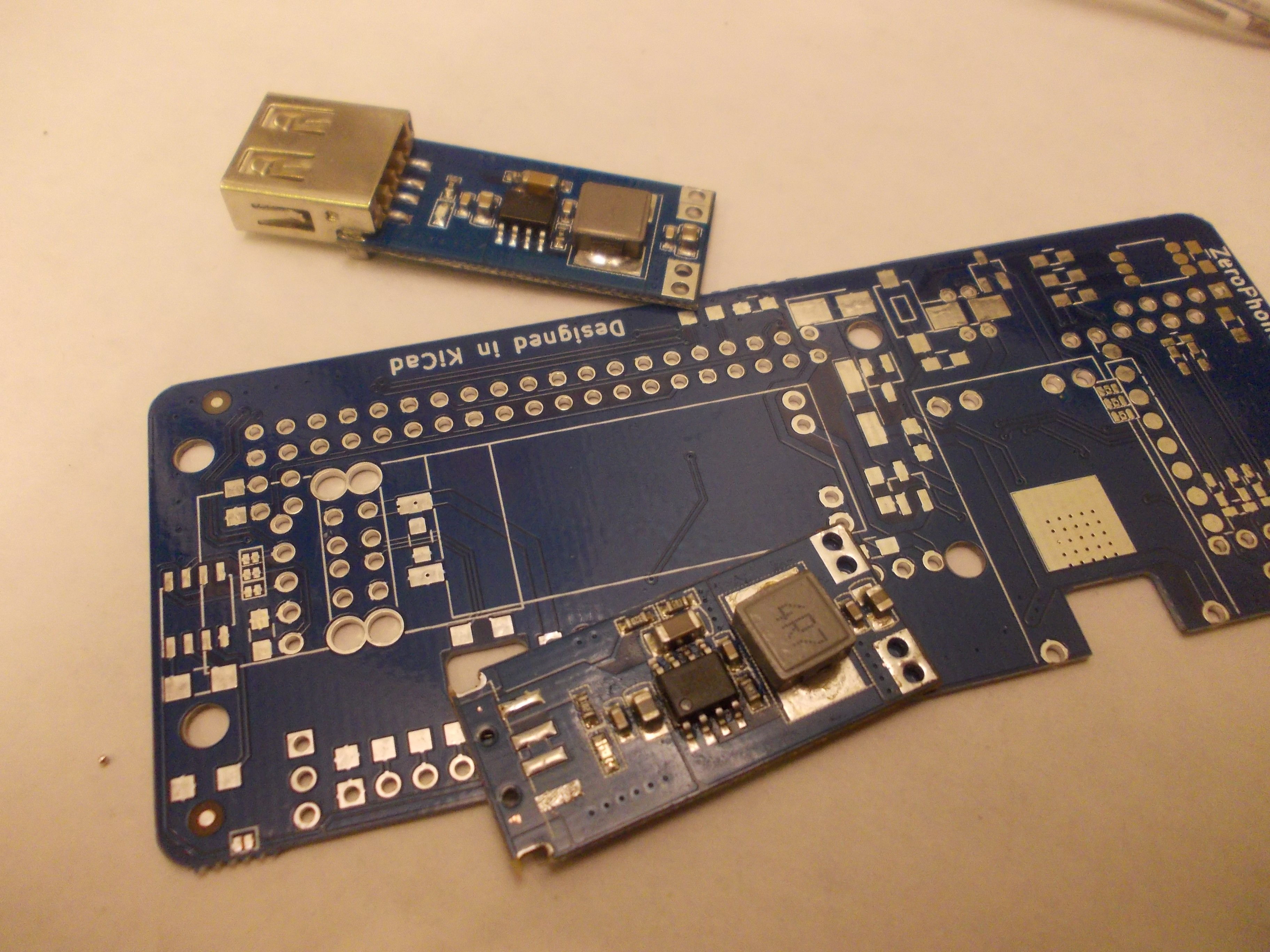
There's an auxiliary, but very useful function on the ZeroPhone - a 5V power supply. It's done using a cheap step-up module, again, from China. Unfortunately, the module itself is not very well-suited for soldering - it can easily be done manually, but it's not as easy to do it automatically. There are two steps that are hard to automate - first, you need to remove the USB port from the module, which involves tearing its tabs off with pliers, then desoldering the 4 remaining pins with a soldering iron. Then, you need to bridge the 5V and GND pins to the ZeroPhone back PCB - with either a piece of wire or metal from a pin header. An in all, it's not easily automatable. I'm wondering if, for mass-production, we could even order these modules with USB ports not soldered on...
![]()
Then there's another question - maybe we should switch to another DC-DC module? This one, despite its size, only really handles about 0.5A, which is really not that much. Using another module could allow using a ZeroPhone as a powerbank, for example - which I've already done multiple times, and the 0.5A limit is kind of noticeable. However, this module is very straightforward and easy-to-use - it's easy to get, easy to solder, it doesn't need configuration (which can be error-prone) and it, in general, just works. So, an alternative would be to develop a mod board that'd optionally replace this DC-DC, providing higher current (and maybe more convenient soldering).![]()
The last thing is power-related. The DC-DC can't handle 5V on its input, so it can't be powered from VSYS bus (3.3V-5V) - as a result, it's powered from the VBAT bus, like the GSM modem. This means that, while ZeroPhone is charging and DC-DC is turned on and powering something else (say, USB-WiFi), the charger is not only charging the battery, but also powering the DC-DC - this, at best, means that the charger never detects when the battery has finished charging, which is something best avoided (there's an overcharge protection on the charger board, so it's more of an inconvenience than something dangerous, though). We could avoid this issue by making the 5V output switch to the charger input when the ZeroPhone is powered on - at its simplest, it could be done with a mechanical switch - but I'm thinking of a BJT+FET-based arrangement, since we already have those in the BOM and an automated solution would reduce the possibility for human error.
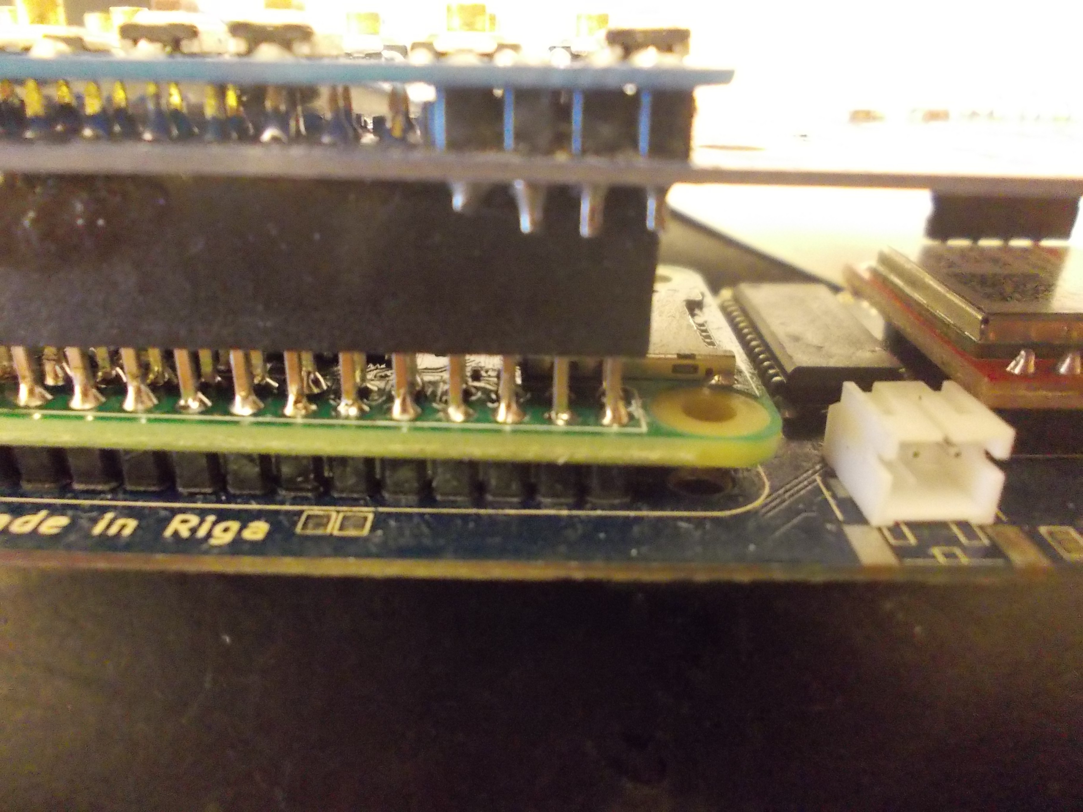
Pi Zero soldering
![]()
This is one of the most problematic areas, in my opinion. The Pi Zero needs to be soldered onto the back board, onto a male pin header - and the front board then connects to the same pin header. The Pi Zero wasn't really meant to be soldered that way, but that's not the big problem - if you add too much solder, the front board won't plug onto the pin header fully, and won't have a good connection. In order to properly solder the Pi Zero onto the pin header, therefore, you need to control the way you're touching the soldering iron tip to the Pi Zero PCB and pin header while soldering, the amount of time you're heating the pin up and the amount of solder you're adding to it. It's also tricky to fix a mistake once you've made it - you need to either use the solder wick or tap the board onto your desk while solder is hot (causing the excess solder to fly away). This is one of the problems that make it hard for me to offer a large number of fully-assembled ZeroPhones during the crowdfunding - but it's also something I don't really feel comfortable leaving to the user to figure out, since if you screw this soldering up completely, it will be really hard to fix. So, I'll also look into automating this process somehow - even though I don't have an idea on how to dispense the solder paste onto the PCB properly.
In addition, at the moment it's necessary to adjust the pin header - make it so that the 40-pin header ends are flush with the back board. It's necessary because, otherwise, the front board's female header might not make proper contact with the male pin header - at least, it's happened on one back board that I assembled recently, experimenting with pin header lengths. I will be investigating it further (since I have other experimental board that makes contact with the female header just fine).
Display breakout traces breaking
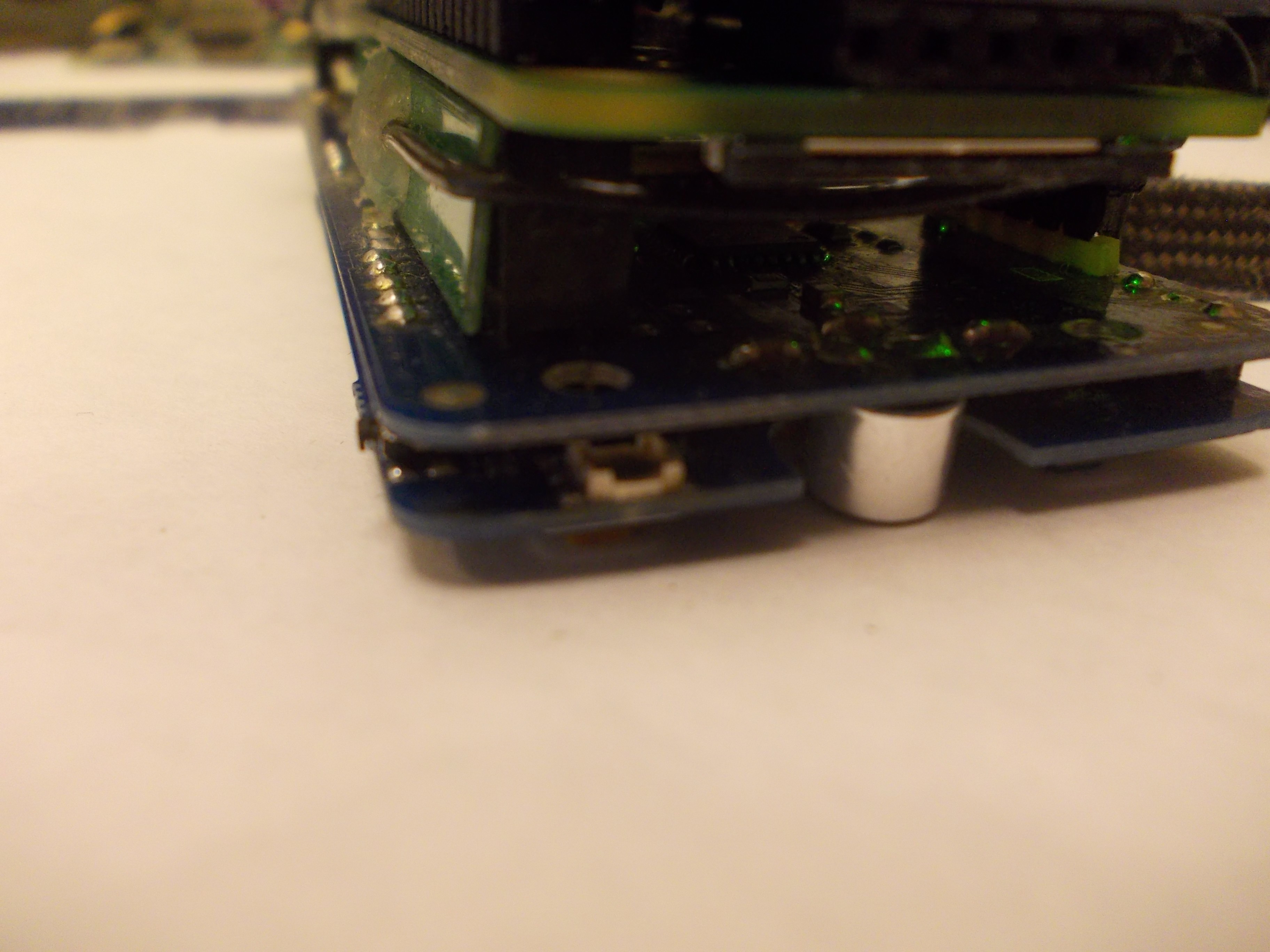
The ZeroPhone has an OLED display breakout PCB on the front board. This PCB is only attached to the front board because it's held by a row of pin headers. Unfortunately, when something is pressing on the display (say, you have a ZeroPhone in your pocket), the resulting mechanical connection flexes unnaturally. This results in PCB traces and plated holes on both PCBs being stressed, which leads to traces breaking (I've already had a couple of display breakout PCBs fail this way). To solve this, we need to make sure the connection doesn't bend - from what I've gathered, we need to put some kind of spacer under the display, so pressing on it won't stress the solder connection, but only the spacer. The spacer, unfortunately, has to be of specific thickness, which makes it harder to have lasercut spacers (as materials for lasercutting aren't usually available in arbitrary thickness) - they will have to be 3D-printed, as a result. So, a 3D-printed model will be designed soon!Back board capacitors
The back board has two big decoupling capacitors - near the GSM modem (VBAT) and the Pi Zero 5V pins (VSYS). They're tantalum capacitors in case D, and they're pretty thick. Since the 18650 and back boards are back-to-back, it results in the 18650 board not being flush to the back board, being at an angle. This is not neat - in particular, it makes it harder to make cases for ZeroPhone. So, the capacitors either need to be split (replacing one capacitor with multiple capacitors in parallel), or low-profile capacitors need to be used - however, low-profile capacitors are expensive. In addition, it's harder to source certain types of capacitors recently, since Apple device production seems to have created artificial scarcity - not only for the capacitors they're using, but also for other types (since most factories are overloaded with making capacitors that Apple has ordered, they have less time for other values of capacitors, which also results in scarcity and prices rising). So, they'll need to be re-thought before production. It's also necessary for us to find some kind of way to avoid fake capacitors (most likely, a reputable supplier) - the kind of capacitors that we're using is a popular target of fake component sellers.
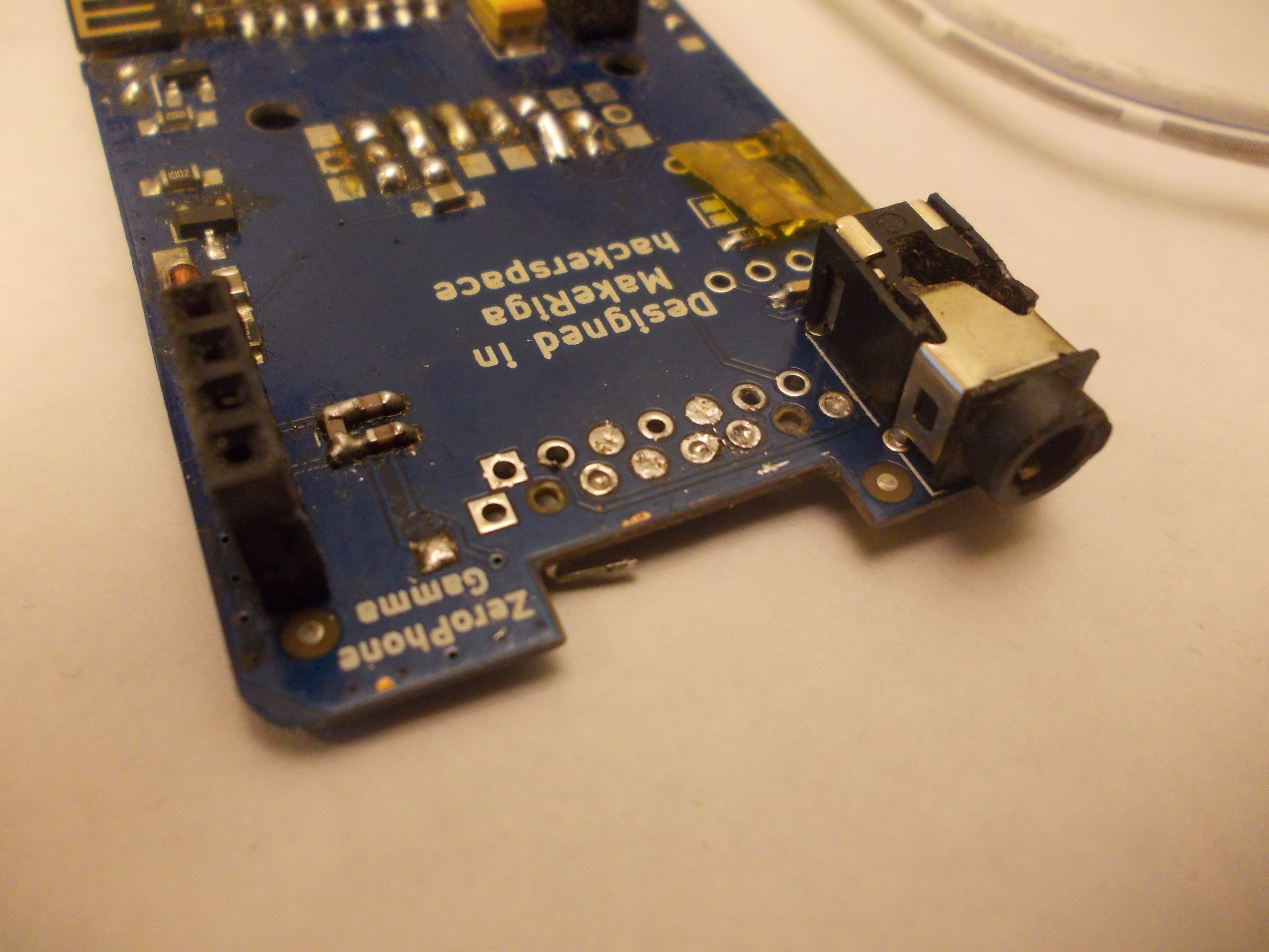
Side buttons
![]()
ZeroPhone keypad has 5 side buttons, soldered on the bottom of the keypad board. These buttons have small plastic actuators (the parts you press on), and they stick out of the keypad board outline - as a result, they break off easily when you're carrying your ZeroPhone without a case. These buttons are also the hardest to replace - once the keypad PCB is soldered onto the front PCB, you can't really desolder the buttons easily, since the gap between front and keypad PCBs is quite small. I don't yet have an idea on avoiding it - these buttons are prone to breaking even when some kind of a case is covering them. However, a case is still in order, undoubtedly - more about that soon, in a separate blog post! ;-)
-
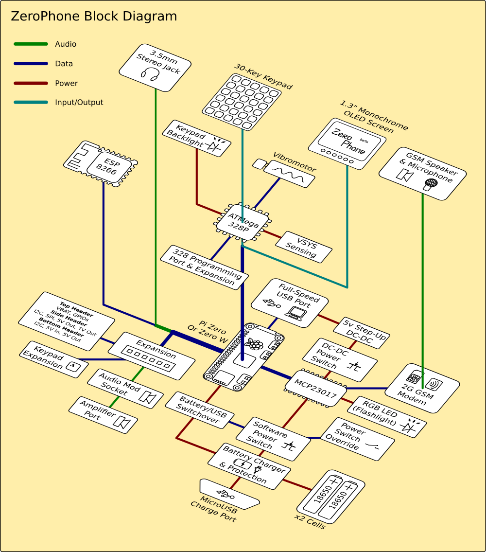
ZeroPhone block diagram
12/25/2017 at 11:17 • 2 commentsMerry Christmas everybody! I'm going through the ZeroPhone project files, and here's something that I haven't yet posted - by @Morning.Star:
![]()
-
Writing a 2048 game for a ZeroPhone
12/10/2017 at 04:21 • 1 commentToday, I was watching my wife play 2048, and I remembered about all the fun I had with this game myself, back when it was popular. While I don't recall ever getting past 512, I did spend a lot of time and I liked it. So, ZeroPhone can fit 8 lines of text on the screen, and 2048 needs a 4x4 playing field - seems like a perfect match!
I found some Python code on GitHub that seems to be a great fit - it's cleanly split into logic and GUI parts, and logic does not depend on the GUI in any way, so can be re-used easily. Now that's a great design, if you ask me =) Reading further into it, it seems to be somebody's programming assignment, and I have to say that it was very helpful of that person to put it on GitHub!
![]()
So, let's reuse the logic part, and build our own UI for the game!
---------- more ----------I could design the game view to be pretty, however, I'd rather make it work first and then go from there. ZPUI doesn't yet provide a lot of facilities to draw pretty UIs on the screen - which is mostly because the move from text-based UI is still ongoing, and I still need to invent a way of coding pretty interfaces that would look great, both on the display and in the code. So, the main problem with lack of pretty UI-making facilities is the fact that I want to make a quick prototype now, and until the facilities are there, it's either "quick" or "pretty" =D
For a start, let's include the logic.py file from the repo. It's MIT-licensed, and ZPUI is licensed under Apache 2.0 - so, let's provide attribution! (commit)
logic.py is an assembly of functions that work on a matrix of numbers (the game field), and each game would have its own matrix. Let's refactor it into an object! (commit)
That took quite a while. In the end, it seems like there won't be anything left from the original code =) Now, let's convert the UI into a ZeroPhone app!
In fact, I don't even need to look at the original UI - 2048 is simple enough of a game so that I can almost instantly understand what's going on. There's a 4x4 field of numbers (basically, a two-dimensional array), four functions that can be straightforwardly attached as key callbacks ("left", "right", "up" and "down"), as well as one function that determines whether the game has ended.
One hour later... Here's the resulting code, let's go through it! First, the imports:
from threading import Event, Lock
from time import sleep

from apps import ZeroApp
from ui import DialogBox, ffs
from helpers import ExitHelper

from logic import GameOf2048
Recently, ZPUI got a new feature - class-based apps. If your app's architecture looks like it'd be best expressed as a class, this is exactly what you need! In our case, this object would be the game app, taking care of managing games and UI:
class GameApp(ZeroApp):

    game = None
    do_exit = None
    is_processing = None
    menu_name = "2048"

    def on_start(self):
        #A flag to tell when the user wants to exit the app
        self.do_exit = Event()
        #A lock to make sure that user's keypresses don't overlay
        self.moving = Lock()
        if self.game is None:
            #No game started yet, starting
            self.start_new_game()
        elif self.game.get_game_state() == 'lose':
            #The last game was lost and abandoned
            #But maybe, just maybe, the user wants to show somebody the result!
            start_new = DialogBox("ync", self.i, self.o, message="Last game lost, start new?").activate()
            if start_new is None:
                return # Picked cancel, exiting the app - user doesn't want to resume playing
            elif start_new is True:
                self.start_new_game() #Discarding the old game and starting a new one
            #If pressed No, we don't start a new game, but don't exit either
        #By now, the `game` property should have a game
        #Let's launch the main loop
        while not self.do_exit.isSet():
            self.game_loop()

    def start_new_game(self):
        #A simple alias
        self.game = GameOf2048(4, 4)
Now we can bind some actions to user's keypresses:
    def set_keymap(self):
        keymap = {"KEY_LEFT": lambda:self.make_a_move("left"),
                  "KEY_RIGHT": lambda:self.make_a_move("right"),
                  "KEY_UP": lambda:self.make_a_move("up"),
                  "KEY_DOWN": lambda:self.make_a_move("down"),
                  "KEY_ENTER": self.confirm_exit}
        self.i.stop_listen()
        self.i.set_keymap(keymap)
        self.i.listen()

    def confirm_exit(self):
        #If the user has pressed OK, we can't just exit the game straight away
        #It might have been an accident!
        #But first, acquiring the lock - so that two keypresses
        #won't ever be processed simultaneously, for whatever reason.
        with self.moving:
            #If game is over, the user is more likely to exit than if the game is still active
            #So let's be a little more user-friendly
            ordering = "ny" if self.game.get_game_state() == 'not over' else "yn"
            do_exit = DialogBox(ordering, self.i, self.o, message="Exit the game?").activate()
            if do_exit:
                self.do_exit.set()
            else:
                #User didn't want to exit the game
                #So, after DialogBox has disappeared from the screen, we need to re-set the keymap
                #and put the game back on the screen
                self.set_keymap()
                self.refresh()

    def make_a_move(self, direction):
        with self.moving:
            #With an argument, we don't need to write four functions, just one
            #And if we need to, we have one central place to debug things in
            assert(direction in ["up", "down", "left", "right"])
            getattr(self.game, direction)()
            self.refresh()
Then, the game's main loop. It takes care of 3 things - keeping track of when game ends, waiting on the game's end screen, then asking the user whether they want to continue the game (or maybe they're bored and want to quit altogether).
    def game_loop(self):
        #In the beginning, need to do this - so that we get the initial game screen and keys respond to actions
        self.set_keymap()
        self.refresh()
        while self.game.get_game_state() == 'not over' and not self.do_exit.isSet():
            #Here, we're simply waiting until the game ends
            #All the fun is happening in another thread, where input callbacks are processed
            sleep(1)
        #We might have two reasons for exiting the "waiting loop":
        #one of them is user quitting the game
        if self.do_exit.isSet():
            return
        #User hasn't prompted for exit, that means the game has ended
        #Waiting for player to click any of five primary keys
        #Then, prompting to restart the game
        eh = ExitHelper(self.i, keys=self.i.reserved_keys).start()
        while eh.do_run():
            sleep(0.1)
        #At this point, the user has pressed some key, so let's ask them what they want to do next
        do_restart = DialogBox("ync", self.i, self.o, message="Restart the game?").activate()
        if do_restart is None: #Cancel - leaving the playing field as-is
            return
            #After this function returns, it'll be launched again
            #And the user will return to the playing field, with the "You won/lost" text
        elif do_restart is False: #No - not restarting, so, exiting the game
            self.do_exit.set()
        else:
            self.start_new_game() #Yes - restarting (game_loop will be entered once more from on_start() )
One important thing about class-based apps - you write a class, and then ZPUI creates an object from that class. That object persists from ZPUI boot until ZPUI exit, so you get persistence for free - this allows us to simply continue the game that was started when the user exits the game, uses some other app and then comes back. However, you need to remember that your object's "on_start()" can be called more than once (just like "callback()" in simpler apps can be).
Earlier, when ZPUI was still pyLCI and worked exclusively with character displays, it only worked with text. Nowadays, it can still output text data on the screen, in a 8x6 font - fitting 8 lines of text, 21 character in each. In our case, it's more than enough for a quick prototype that will, nevertheless, look good and work well enough to be shipped with ZPUI.
To generate a game UI, we're using lots of Python string functions and a little bit of ASCII art (if using dots as placeholders can be called "ASCII art"):
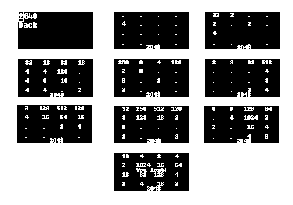
    def display_field(self, field):
        #These asserts act more like warnings to tell that this function
        #hasn't been tested with playing fields other than 4x4
        assert len(field) == 4, "Can't display a field that's not 4x4!"
        assert len(field[0]) == 4, "Can't display a field that's not 4x4!"
        #Constructing an array of strings to be sent to the display
        display_data = []
        #We need to designate some space for each cell of the playing field
        #So that the numbers don't move when they increase and move around
        #With 21 character, each cell will be 5 characters wide - more than OK
        space_for_each_number = self.o.cols / len(field[0])
        for field_row in field:
            #A dot is a good placeholder, it's small but it's there
            #And we can't draw lines on the screen from here anyway
            field_row_str = [str(i) if i else "." for i in field_row]
            #Now, let's actually build a row of the playing field
            display_row = "".join(str(i).center(space_for_each_number) for i in field_row_str)
            #I guess it could've been more readable.
            display_data.append(display_row.ljust(self.o.cols))
            #Adding a "spacer" - just an empty row
            display_data.append(" "*self.o.cols)
        #Now we have 8 rows, but we need to overlay some more text
        #Replacing the center row with the game state, if we need to show it:
        game_state = self.game.get_game_state()
        #Creating a dictionary and getting an item from it in one go
        state_str = {"win":"You won!",
                     "lose":"You lost!",
                     "not over":""  }[game_state]
        display_data[3] = state_str.center(self.o.cols)
        #Let's add the game name in the footer
        #No real need to do it, but why not
        display_data[7] = "2048".center(self.o.cols)
        return display_data

    def refresh(self):
        #A simple function that draws current state of the game on the screen
        displayed_field = self.display_field(self.game.get_field())
        self.o.display_data(*displayed_field)
Now, a quick collage from screenshots I made during a test game:
![]()
As a result of this, there's the first, simple game for ZeroPhones, and it's already in the latest ZPUI code! You, too, can help - here's a GitHub issue describing what features it'd be great to add to this game. This GH issue is not even about this particular game, it's more about writing code that other people can then re-use as examples of implementing this particular feature - that's why your input here would be useful for the ZeroPhone project.
There's only one problem that I see now - the game seems too simple! This means that there might be some constraint that I'm missing. However, there are more important tasks for ZPUI at the moment, so I'll limit myself to what I've already done, for the time being =)
As a conculsion, I'd like to thank the ZeroPhone project's contributor, monsieur_h, for implementing the "class-based apps" feature in ZPUI. This feature is something that I wouldn't have paid attention to myself, but it's definitely a feature I'm going to use, having tried it now!
-
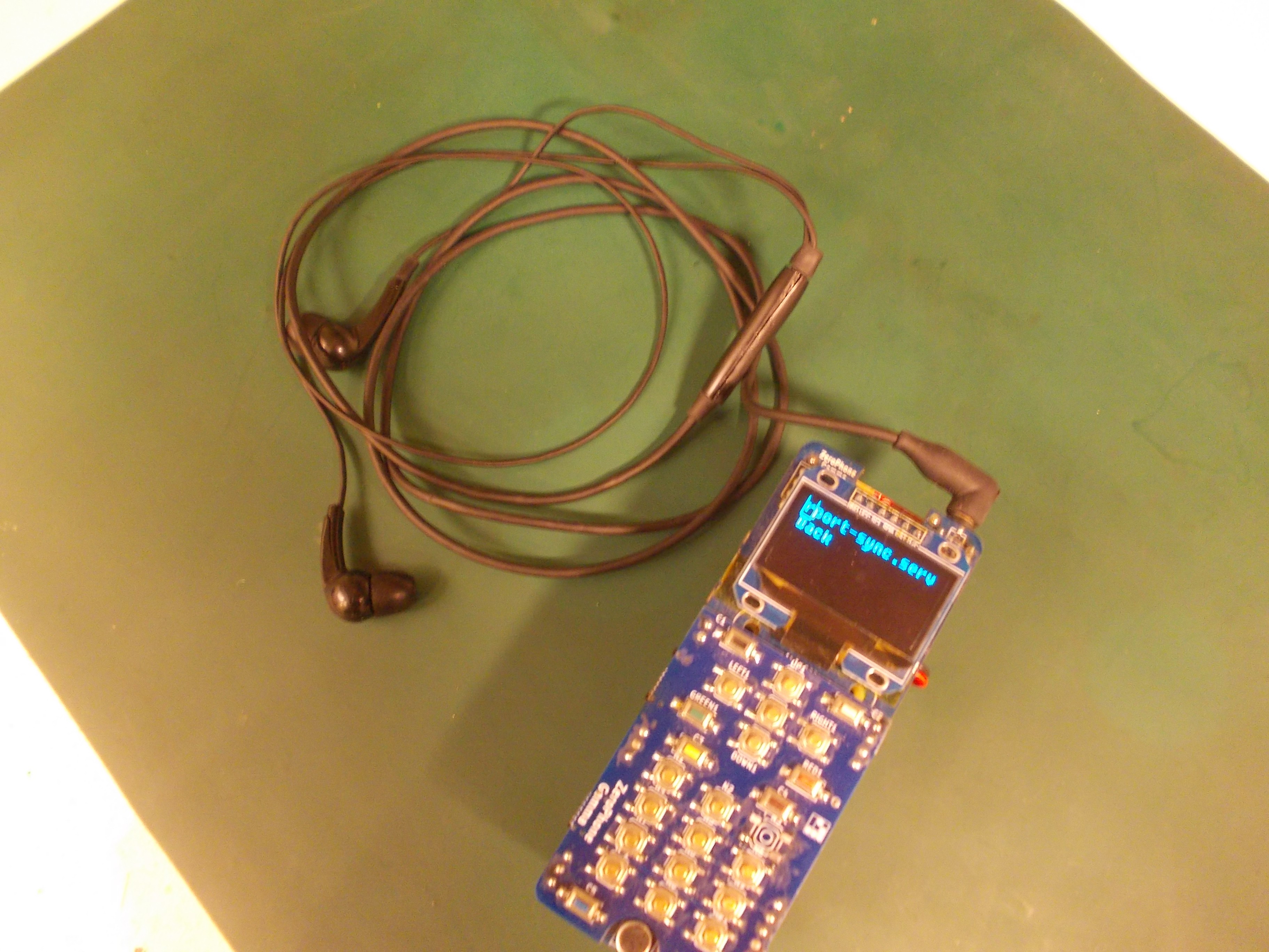
ZeroPhone uses: streaming audio from desktop to headphones
11/13/2017 at 06:43 • 0 commentsDo you ever feel tethered to your computer because you're wearing headphones, and you can't go away from it because you can't use your speakers for whatever reason? This is for you.
I often found myself in this situation. Sometimes I'm listening to podcasts, and I want to get up from my desk and grab something from other room, but the speakers aren't loud enough. Sometimes people around are sleeping and I don't want to wake them up, but I also can't carry my laptop with me just because I like the track I just found on YouTube.
![]()
One of ZeroPhone plans is enabling hands-free applications, using audio for things like notifications (of course, only the most important ones, and the ones you want to hear.) Naturally, I'll be using it a lot - I'm the "headphones" kind of person, and I know there are plenty of ZeroPhone notifications I'll want to hear about immediately when they happen. Now, what if I want to listen to a podcast, should I unplug headphones from my ZeroPhone and not hear the notifications? The most obvious idea is using the ZeroPhone as an audio receiver, and stream audio from my laptop to ZeroPhone, so that notifications could be overlayed, and I wouldn't find myself re-plugging the headphones all the time.
So, the setup is like this: I want to stream all audio from my Windows laptop to my ZeroPhone, which sits in my pocket, receives the audio stream and plays it back to my headphones. If my laptop ran Linux, I could just use pulseaudio network streaming capabilities and be done with it. As it's Windows, though, I needed to find something that would work on Windows and would be more user-friendly than using a long command-line copy-pasted from Stackoverflow.
---------- more ----------I found TuneBlade, which is not open-source, but is free when used with an open-source receiver - just stellar! I'll think about buying their Pro version just to support the developers, at least, when I'm less broke.
Then, I've searched for receiver software that would be easy to set up, and I found Shairport Sync - it's claimed to work for the "receiver" part, and it's open-source, so supported by the free version of TuneBlade! I also found an up-to-date tutorial on compiling Shairport Sync (pro tip: when looking up tutorials in Google, limit search results to "during the last year" to get rid of outdated tutorials). Unfortunately, shairport-sync is not available in Raspbian repos, even though their GitHub claims it's available in Debian. Nevertheless, following the tutorial, compiling it was straightforward:
sudo apt-get update
sudo apt-get upgrade
sudo apt-get install autoconf automake avahi-daemon build-essential git libasound2-dev libavahi-client-dev libconfig-dev libdaemon-dev libpopt-dev libssl-dev libtool xmltoman
git clone https://github.com/mikebrady/shairport-sync.git
cd shairport-sync
autoreconf -i -f
./configure --with-alsa --with-avahi --with-ssl=openssl --with-systemd --with-metadata
make
You should be able to just copy-paste these lines in the terminal, follow the instructions and be done with it. It feels awesome - compiling stuff on my ZeroPhone and understanding that it's all happening in my pocket.
The last line is:
sudo make installHowever, I would rather build a package. There's a "checkinstall" software which would do that for me, too!
sudo apt-get install checkinstall
checkinstall
Checkinstall can ask all kinds of questions, but in this case, git repository of Shairport Sync already contained all the metadata necessary for building a Debian package, so it picked that up and made a nice .deb package called shairport-sync_3.0-1_armhf.deb . Let's install it:
sudo dpkg -i shairport-sync_3.0-1_armhf.deb
sudo groupadd shairport-sync #For some reason, the package creates the group, but not the user
Done!
If required, you can also edit Shairport-Sync settings (such as the Airplay receiver name and password, at the very least) in config file, which, when compiling from source, seems to be put into /usr/local/etc/shairport-sync.conf .
Last steps - enabling it to run on system boot (or not):
systemctl enable shairport-sync
Now, the only thing remaining is to create an app it, so that you can control the Airplay receiver from the GUI - start, stop, restart, as well as change the name and the password. I've seen a mention of Shairplay getting a DBus interface some time in the future, but, if I recall correctly, that is not a priority - so editing the config file & calling systemctl commands will have to do. I'll look into it over the weekend - this will be a good reason for me to convert the small systemctl module I wrote into a full-blown Python library!
-
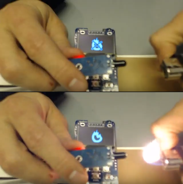
An in-depth explanation of a simple GPIO app
11/08/2017 at 04:09 • 0 commentsFor Hackaday Prize video, I made some simple ZPUI apps (some of them were mockups, though). One of them was reading an external flame sensor and displaying pictures on the screen depending on whether the sensor detected flame or not. I had to do this in a rush, and I ended up adding some basic, but very useful, functions to ZPUI (though I did have to clean them up quite a bit before I could merge them into official ZPUI version =) ).
![]()
What's the algorithm of this app?
Set up the GPIO
In a loop, read from the GPIO pin
If pin has logic low on it:
    display picture of fire
Else:
    display picture of fire crossed out
The app is, therefore, very short. So, let's go through it thoroughly, explaining it in as much detail as possible!
---------- more ----------Once again, ZPUI apps are a separate directory, with __init__.py and main.py . __init__.py is supposed to be empty, and main.py has to have following variables&functions:
- menu_name - app name for ZPUI menu (if omitted, app directory name will be used)
- init_app(i, o) - a small app initialization function, gets i and o, typically would just set them to module-global variables like this:
i = None; o = None
...
def init_app(input, output):
    global i, o
    i = input; o = output
Having globals named as i and o is not strictly necessary and is up to the app programmer, just a convention used by default - one that allows to easily pass i and o to UI elements, as well as allow for easy copy-pasting of examples that are provided with ZPUI. For now, init_app() return value doesn't matter. - callback() - function that gets called when app is activated, that is, selected from the menu. So, if you have an app named "My first app", you go to the app menu and press "My first app", the callback() function from main.py will be called. For now, callback() return value doesn't matter - what happens inside the callback() is what matters. Typically, you'd activate some UI element there, and you could also do some setup before&after.
Now, pretty much the only input for our app is reading from a GPIO. I've picked a GPIO from the 13-pin expansion header, connected it to the flame detector's digital output (active low), connected VCC and ground to it - all that's necessary from the hardware side. On the hardware side, I'll be using RPi.GPIO library. Something that we have to take into account is: 1) you need to set GPIO into the right state before being able to do something with it 2) once you've set it, other applications can still use it, as well as set it up differently 3) if something sets up GPIO the wrong way in the background, you either get an unexpected exception, or just silent failure - and you certainly don't get the result you wanted. The last thing might result in the app getting its rug pulled from under it, so we need to take that into account.
So, how do we set up the GPIO state the right way, to be exact, where do we put the setup statements? We could do that pretty much anywhere in the main.py - but there are caveats, as there are at least 3 different places to add the GPIO setup statements.
1 - Initialize GPIOs on import
We can add it on the first level, so that it's run right after the module import, something like this:
...
from RPi import GPIO
GPIO.setmode(GPIO.BCM)
GPIO.setup(18, GPIO.IN)
...
Or like this:
...
GPIO.setmode(GPIO.BCM)
GPIO.setup(18, GPIO.IN)
def init_app(i, o):
    ...
However, this positioning is problematic, since if other app sets up this GPIO to something else, this app won't ever set it back to what it needs to be. Say, we import all the apps, first the "flame detector" app, then the "GPIO playground" app (allowing to switch/read GPIOs from the UI). If both apps set up the GPIOs when they're imported, the "flame detector" app won't work properly, and likely won't even know about it =(
There are two more problems with "set things up when app is imported" approach that don't apply here, but might in a slightly more complicated case. First, if the GPIO number is to be determined at runtime, it won't work. If you need to do something time-consuming (like importing a big library, even), that means importing your app will take a long time, and it'll therefore make ZPUI load slower. If you depend on some external resources, they might not yet be available, and if you don't handle that gracefully and your app throws an exception, it won't get loaded. Lastly, you can't set up UI elements during import, since i and o (references to input and output device objects) aren't yet populated at this point.
2 - Initialize GPIOs in init_app():
The init_app() is run on ZPUI startup, when the app is loaded - right after importing it. The only difference between "set things up in init_app()" and "set things up on import" is that init_app gets i and o variables, so, init_app is where you'd set up UI elements, since you can't do that earlier. Other than that, the drawbacks are the same as with the previous way.
3 - Initialize GPIOs in callback():
The callback() function is only run when app is activated from the menu, to be exact, it's called each time you press the ENTER button when you're in the app menu and the app is selected. That seems to be the perfect place to put the GPIO initialization - as long as other apps don't interfere (from a background thread or even other process), the app will always have the GPIO set up the right way when it needs it. Possible drawbacks to putting initialization of your resources in callback(), that don't apply in the case of GPIO initialization:
- If initialization were to be a time-consuming process (for example, you'd be loading a database), it'd add a delay between the user pressing ENTER and app appearing on the screen. Most apps appear on the screen almost instantly, so you might be making the user feel like the UI just hung - especially if callback() would take 10 seconds. So, there's now a "background process" helper that allows you to launch the app initialization process in the background, and keep track of when it's done!
- If initialization only has to be done once, it's best if it's done as an oneshot process. This also applies if the initialization can be done more than once, but takes a lot of time - why would you be wasting user's time if it's not necessary? In that case, you can even use oneshot helper together with background process helper. Also, don't make the user lose the app's state if they would most likely need it preserved - for example, if your app allows the user to take some action but needs to be set up for this action first, it would most likely make the most sense to save user's settings from the last time user worked with the app and offer them the next time they use it.
Now that we got through the hardest part, let's see about the easiest part!
At the time when I was writing the app, displaying an image would need at least 4 lines of code. In contrast, displaying text would only take one:
PrettyPrinter(text, i, o, sleep=3)So, I made it work all the same!
def GraphicsPrinter(image, i, o, sleep_time=1, invert=True):
    GraphicsPrinter.exit_flag = False
    def exit_printer():
        GraphicsPrinter.exit_flag = True
    if i is not None:
        i.stop_listen()
        i.clear_keymap()
        i.set_callback("KEY_LEFT", exit_printer)
        i.set_callback("KEY_ENTER", exit_printer)
        i.listen()
    if invert: image = do_invert(image)
    image = image.convert(o.device.mode)
    o.display_image(image)
    poll_period = 0.1
    if sleep_time < poll_period*2:
        sleep(sleep_time)
    else:
        sleep_periods = sleep_time/poll_period
        for period in range(int(sleep_periods)):
            if GraphicsPrinter.exit_flag == True:
                return #Exiting the function completely
            sleep(poll_period)
Invocation:
path = "fire.png"
image = PIL.Image.open(image_path).convert('L')
GraphicsPrinter(image, i, o, 0.1)
GraphicsPrinter needs an image, but we don't yet have it loaded. So, we can add a helper function that takes a path to an image, loads it and then calls GraphicsPrinter:
def show_image(image_path):
    if not os.path.isabs(image_path):
        image_path = os.path.join(app_path, image_path)
    image = PIL.Image.open(image_path).convert('L')
    GraphicsPrinter(image, i, o, 0.1)
Hmm... Now that I'm writing this, it could also accept a path, as a text string! Let me just add this feature real quick:
def GraphicsPrinter(image_or_path, i, o, sleep_time=1, invert=True):
    """Outputs image on the display, as soon as it's called.

    Args:

        * ``image_or_path``: Either a PIL image or path to an image to be displayed.
        * ``i``, ``o``: input&output device objects. If you don't need/want exit on KEY_LEFT, feel free to pass None as i.

    Kwargs:

        * ``sleep_time``: Time to display the image
        * ``invert``: Invert the image before displaying (True by default) """
    if isinstance(image_or_path, basestring):
        image = PIL.Image.open(image_or_path).convert('L')
    else:
        image = image_or_path
Much better, we got rid of one import and one function in the app - the app just became even shorter! I lost the "use relative path seamlessly" feature, but I can just make a small helper, and still call GraphicsPrinter directly.local_path = lambda x: os.path.join( os.path.dirname(sys.modules[__name__].__file__), x ) ... GraphicalPrinter(local_path("fire.png"), i, o, 0.1)Now, let's add a loop that'll be reading the GPIOs and showing the different images depending on its state:
while True:
    state = GPIO.input(18)
    if state:
        GraphicalPrinter(local_path("no_fire.png"), i, o, 0.1)
    else:
        GraphicalPrinter(local_path("fire.png"), i, o, 0.1)
The time for each iteration of the app is mostly defined by how long GraphicsPrinter runs. As we've set it to sleep for 0.1 second, that's approx. how long it will take. We can't make the loop run too quickly, since it'll unnecessarily load the CPU.
Now, the hardest part is - how do we exit the app? At any point, pressing LEFT (default for exiting the UI element you're in, or exiting the app) will only exit the GraphicsPrinter itself, which won't even be noticeable, given that it only runs for 0.1 second - the outer loop won't ever get a signal that it has to exit. So, the problem is that LEFT key callbacks are handled by the GraphicsPrinter UI element and the loop doesn't handle anything.
Let's fix that! We can set up a callback on the KEY_LEFT that'd be checked by the loop. In fact, we don't need to set any callbacks manually - I've added a helper that adds all the callbacks itself, and adds an easy way to check whether the button has been pressed!
eh = ExitHelper(i).start()
while eh.do_run():
     #the loop will run until "left" key on the keypad is pressed.
However, we also need to make sure the GraphicsPrinter doesn't add its own callback on the KEY_LEFT (overwriting our callback that the helper sets) - thankfully, we can just pass None instead of i:
GraphicsPrinter("fire.png", None, o, 0.1)
The resulting app:
menu_name = "Flame detector"

from RPi import GPIO
import sys
import os

from helpers import ExitHelper
from ui import GraphicsPrinter

local_path = lambda x: os.path.join( os.path.dirname(sys.modules[__name__].__file__), x )

i = None; o = None

def init_app(input, output):
    global i, o
    i = input; o = output

def callback():
    GPIO.setmode(GPIO.BCM)
    GPIO.setup(18, GPIO.IN)
    eh = ExitHelper(i).start()
    while eh.do_run():
        state = GPIO.input(18)
        if state:
            GraphicsPrinter(local_path("no_fire.png"), None, o, 0.1)
        else:
            GraphicsPrinter(local_path("fire.png"), None, o, 0.1)
As a result, we have an app that works for the purpose, uses external resources (GPIOs) but doesn't interfere with other apps, doesn't block the user from exiting it, and its code is short but concise. While writing this worklog, I've also added plenty of helpers and improvements to ZPUI!
App's purpose is fairly limited, though, so now I'm thinking of adding something like a BASIC interpreter to the UI, allowing to write short&simple apps while making use of ZeroPhone hardware. Would make for a fun weekend project! (I think that would even count as a project priority, eventually)
ZeroPhone - a Raspberry Pi smartphone
Pi Zero-based open-source mobile phone (that you can assemble for 50$ in parts)


 During the manufacturing, we'll need to find a way to either find a reliable source for these modules, or to manufacture our own (I've already reverse-engineered the schematics and the PCB, thankfully, and I'm asking for manufacturing quotes) - as a backup plan in case the commercial modules are no longer suitable for us. I've also tried understanding the problem by comparing "old" and "new" modules - I've checked the schematic and it's the same (the boards are slightly different, but the changes are minimal), so my guess is that the "new" modules are using cheaper components, which causes the failures. But, just in case, I'm going to see if there's a way for us to source these boards reliably.